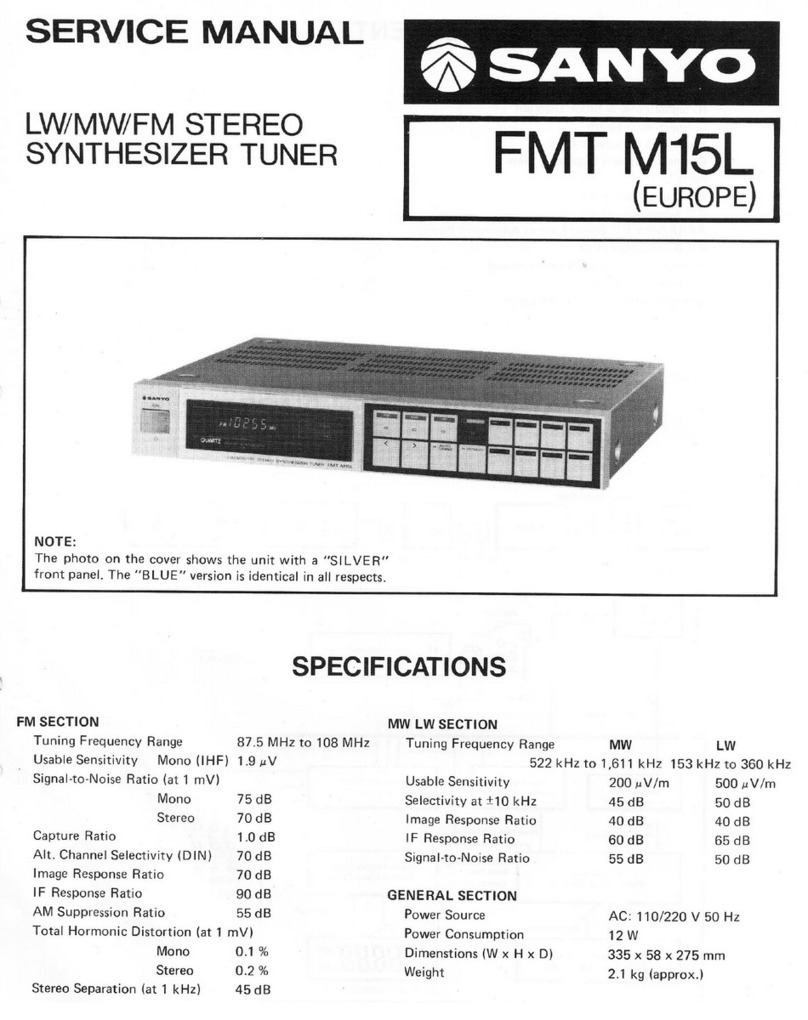
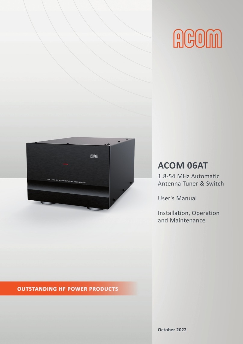
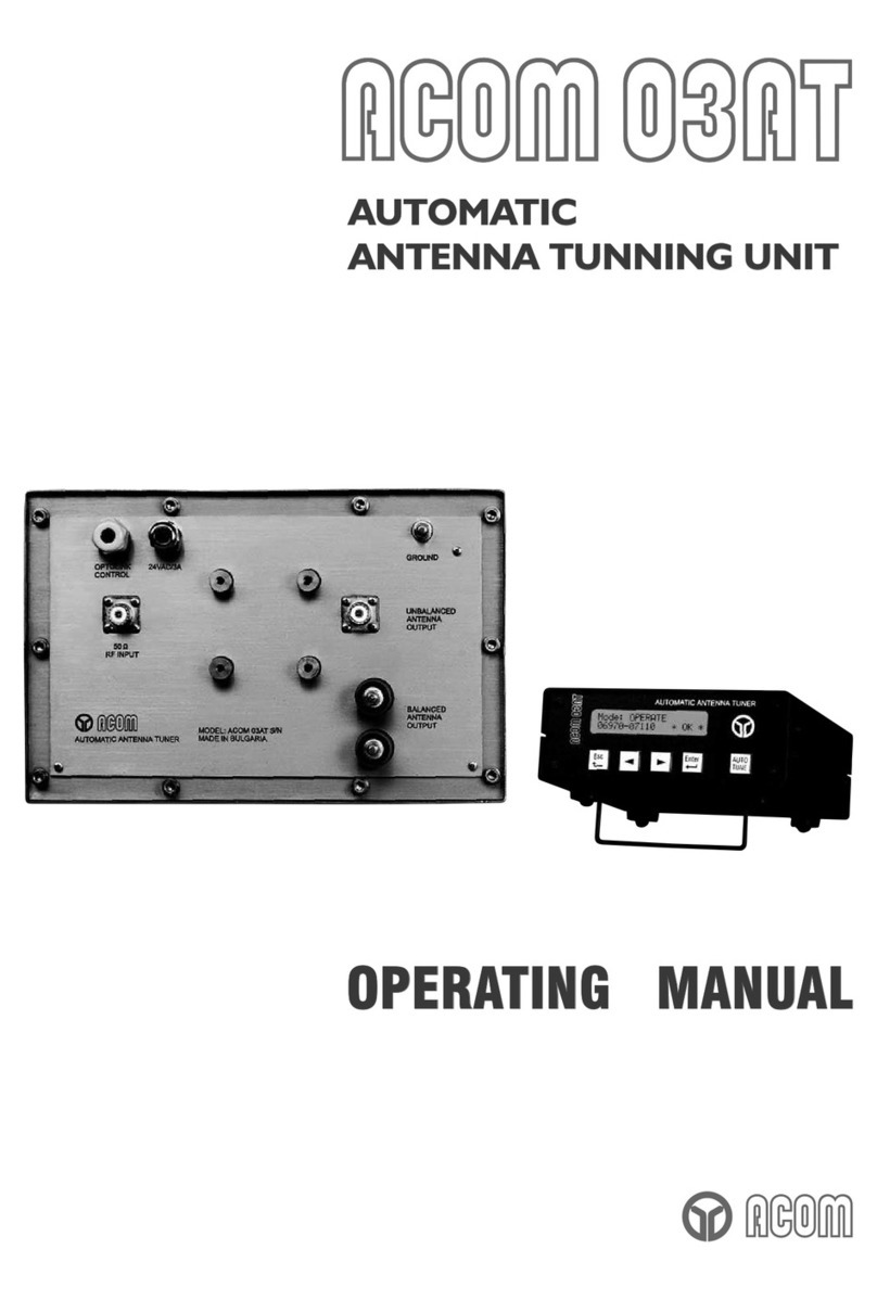
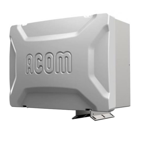
Acom AOM 04AT User manual

ACOM 04AT
Remote Automatic
Antenna Tuner and Switch
User's Manual
Installation, Operation
and Maintenance
October 2023
OUTSTANDING HF POWER PRODUCTS

User's Manual | ACOM 04AT | Remote Automatic Antenna Tuner and Switch
Page 2of 88 | S e c t i o n ABOUT DOCUMENTATION
October 2023
This manual is for electronic distribution mainly.
If you have it on paper and you no longer need it, please, recycle it!
The latest versions of our User's Manuals are available at
www.acom-bg.com

User's Manual | ACOM 04AT | Remote Automatic Antenna Tuner and Switch
October 2023
S e c t i o n ABOUT DOCUMENTATION | Page 3of 88
ABOUT DOCUMENTATION
All ACOM documentation (including manuals, brochures, specifications, descriptions, presentations, video
materials, etc.) are based on the latest available information at the time of creation of our documents.
As we always strive to constantly improve and update our products, ALL PRODUCTS, PRODUCT
SPECIFICATIONS AND DATA ARE SUBJECT TO CHANGE. ACOM reserves the right to make changes and
improvements at any time without further notice or obligation to notify any person or organization of such
revisions or changes, made in order to improve the reliability, function, quality and design, and/or
performance of the ACOM products and services.
Further, this User's Manual is provided AS IS and ACOM shall not be liable for possible errors contained
herein.
ACOM company creates and distributes its documentation in ENGLISH language only.
Any translations in other languages made by our dealers, partners, distributors, etc. cannot
be related to ACOM company in any way.
ACOM is not liable for non-English documentation correctness in any way.
We are continuously striving to improve our documentation, but nobody is perfect.
And our documentation is not an exception of this rule.
Have you found any errors or would you like to suggest changes in our documentation?
Please help us by sending your suggestions to the following e-mail address:
documentation@acom-bg.com
The latest versions of our User's Manuals are available at
www.acom-bg.com
We highly recommend you to use this manual in electronic form as PDF-file instead of printed version. The
PDF-file is easy to read on any computer, tablet, smart phone or other similar device. In the PDF file you will
find the necessary information very fast due to context-oriented links (marked in orange) inside the file,
including context-linked Table of Content.
To open PDF-files you can use any free PDF viewer, for example:
-Adobe Acrobat Reader DC (https://get.adobe.com/reader);
-Foxit Reader (https://www.foxitsoftware.com/pdf-reader);
-Your web browser. Web browsers like Google Chrome, Firefox, and Safari all have integrated PDF
readers.

User's Manual | ACOM 04AT | Remote Automatic Antenna Tuner and Switch
Page 4of 88 | S e c t i o n ABOUT DOCUMENTATION
October 2023
Title of Documentation
ACOM 04AT Remote Automatic Antenna Tuner and Switch
User's Manual
Installation, Operation and Maintenance
Type of Documentation
User's Manual
Purpose of Documentation
This manual explains Installation, Operation and Maintenance of the
ACOM 04AT Remote Automatic Antenna Tuner and Switch.
Record of Revisions
Description
Release Date
Notes
ACOM 04AT User's Manual
-
First edition
ACOM 04AT User's Manual
-
Second edition
ACOM 04AT User's Manual
25.04.2018
Third edition
ACOM 04AT User's Manual
21.05.2021
Fourth edition, R01
ACOM 04AT User's Manual
31.10.2022
Fourth edition, R02
ACOM 04AT User's Manual
04.10.2023
Fourth edition, R03
Validity
The specified data is for product description purposes only and may not be
deemed to be guaranteed unless expressly confirmed in the contract. All
rights are reserved with respect to the content of this manual and the
availability of the product.
Copyrights
© 2023 ACOM Ltd.
Copying this document, giving it to others and the use or communication
of the contents thereof without express authority, are forbidden.
Offenders will be held liable for infringement of any intellectual property
of ACOM Ltd. and all damages which may rise as a result.
Trademarks
ICOM, KENWOOD, YAESU, ELECRAFT, and other product names or brands
mentioned in this documentation are either registered trademarks or
trademarks of their respective holders.
Published by
ACOM Ltd.
Bulgaria | Bozhurishte 2227
Sofia-Bozhurishte Industrial Park | 6 Valeri Petrov Str.
GPS coordinates: 42.748616о| 23.209801о
Web: www.acom-bg.com
E-mail: documentation@acom-bg.com
Note
This manual has been printed on chlorine-free bleached paper.

User's Manual | ACOM 04AT | Remote Automatic Antenna Tuner and Switch
October 2023
S e c t i o n ABOUT DOCUMENTATION | Page 5of 88
Contents
ABOUT DOCUMENTATION ................................................................................................................................ 3
1. GENERAL INFORMATION......................................................................................................................... 10
1.1. Introduction and Description........................................................................................................ 10
1.2. To the Reader of this Manual........................................................................................................ 12
1.3. Product Features........................................................................................................................... 13
1.4. Product History and Documentation Validity ............................................................................... 15
1.5. Additional Documentation............................................................................................................ 15
1.6. Product Identification ................................................................................................................... 16
1.7. Equipment Supplied...................................................................................................................... 16
1.8. Owner Assistance.......................................................................................................................... 17
1.9. Safety Considerations, Explicit Definitions.................................................................................... 18
1.9.1. Lightning protection when the tuner is installed in a building........................................ 20
1.9.2. Lightning protection when the tuner is installed outdoor .............................................. 21
1.9.3. Electric Safety Precautions .............................................................................................. 22
1.9.4. General Safety Precautions ............................................................................................. 22
2. INSTALLATION.......................................................................................................................................... 23
2.1. Unpacking and Initial Inspection................................................................................................... 23
2.2. Tuner Location Selection............................................................................................................... 26
2.3. Power Supply Voltage ................................................................................................................... 27
2.4. Installation and Connection for Outdoor Operation..................................................................... 28
2.4.1. If the wall mounting option is chosen ............................................................................. 30
2.4.2. If the mast mounting option is chosen............................................................................ 32
2.4.3. Connections for Outdoor Operation ............................................................................... 34
2.5. Installation and Connection for Indoor Operation........................................................................ 36
2.5.1. If the desk mounting option is chosen ............................................................................ 36
2.5.2. Connections for Indoor Operation .................................................................................. 38
2.6. Grounding, Additional Information............................................................................................... 41
2.6.1. Lightning Protection Grounding ...................................................................................... 41
2.6.2. Grounding for Protection from Electric Shock................................................................. 41
2.6.3. Radio Frequency Grounding or Counterpoise................................................................. 41
2.7. Connecting RF Cables, Additional Information ............................................................................. 41

User's Manual | ACOM 04AT | Remote Automatic Antenna Tuner and Switch
Page 6of 88 | S e c t i o n ABOUT DOCUMENTATION
October 2023
3. GETTING STARTED................................................................................................................................... 43
3.1. Turning ON and OFF...................................................................................................................... 43
3.2. Indication, controls and menus..................................................................................................... 44
3.2.1. Tuner Information Area on the Amplifier Screen............................................................ 44
3.2.2. SEGMENT UP/DOWN buttons (Second Function - BAND)............................................... 45
3.2.3. TUNE button (Second Function - BYPASS)....................................................................... 45
3.2.4. АNT Button (Change of Antennas) .................................................................................. 46
3.2.5. Tuner Related Menus ...................................................................................................... 46
4. STARTING UP AND MAIN FUNCTIONS..................................................................................................... 47
4.1. What is tuning type / Rate (Selectivity Degree, Sharpness).......................................................... 47
4.1.1. SHARP .............................................................................................................................. 48
4.1.2. REGULAR.......................................................................................................................... 48
4.1.3. WIDE ................................................................................................................................ 48
4.1.4. FIXED................................................................................................................................ 49
4.2. Tuner Assignment and Unassignment .......................................................................................... 49
4.3. Tuning Modes: FULL, QUICK and BYPASS...................................................................................... 49
4.4. Quick Tuning and Non-Volatile Memory....................................................................................... 50
4.5. Operation in BYPASS Mode........................................................................................................... 51
4.6. Changing Frequencies and Antennas............................................................................................ 52
4.7. Specific of Operation in TRANSMISSION Mode ............................................................................ 52
4.8. Power Reduction at Overload ....................................................................................................... 52
5. BASIC FULL TUNING CYCLE ...................................................................................................................... 53
5.1. What a Full Tuning Cycle Does...................................................................................................... 53
5.2. Operator Actions for a Full Tuning Cycle....................................................................................... 54
5.2.1. Full Tuning for Transceivers with CAT ............................................................................. 54
5.2.2. Full Tuning for Transceivers without CAT Capability....................................................... 54
6. ADVANCED FUNCTIONS AND OPTIONS................................................................................................... 56
6.1. ANTENNA ASSIGNMENT Menu ..................................................................................................... 56
6.1.1. Antenna Assignments by Bands ...................................................................................... 56
6.1.2. Setting the Tuning type / Rate (Sharpness, Selectivity), (S, R, W, F) ............................... 56
6.1.3. Editing Antenna Names ................................................................................................... 57
6.2. Maintenance Functions - ATU SERVICE Menu .............................................................................. 57
6.2.1. ATU Individual Data......................................................................................................... 57

User's Manual | ACOM 04AT | Remote Automatic Antenna Tuner and Switch
October 2023
S e c t i o n ABOUT DOCUMENTATION | Page 7of 88
6.2.2. ATU Status ....................................................................................................................... 57
6.2.3. Deletion of Individual or Group of Stored Tuning settings.............................................. 57
6.2.4. Erasing the Whole NON-Volatile Memory....................................................................... 58
6.2.5. Checking the Resource Used for the Current Tuning ...................................................... 58
6.2.6. Dumping the NON-Volatile Memory in a File on a PC..................................................... 58
6.2.7. Restoring (Loading) the NON-Volatile Memory from a File - Memory Load from File ... 60
6.2.8. Aging and Refreshing of Settings..................................................................................... 61
6.3. Overview of TUNING SETTINGS and Resources Used................................................................... 62
6.4. Measurements in the Tuner - ATU MEASURE Menu .................................................................... 63
6.4.1. Voltage and Current at the Antenna Output................................................................... 64
6.4.2. Reflected Power, Forward Power and SWR at Antenna Output..................................... 64
6.4.3. Power Supply Voltage and Temperature in the Tuner Unit ............................................ 64
6.4.4. Tuner Working Hours....................................................................................................... 64
7. MAINTENANCE ........................................................................................................................................ 65
7.1. Periodic Maintenance ................................................................................................................... 65
7.2. Cleaning......................................................................................................................................... 65
7.3. Fuse Replacement......................................................................................................................... 65
7.4. Block Diagram and Principle of Operation.................................................................................... 68
7.5. Troubleshooting - Monitoring the Antenna-feeder Path Status................................................... 72
8. SPECIFICATIONS....................................................................................................................................... 74
8.1. Parameters.................................................................................................................................... 74
8.1.1. Operating Frequency Range ............................................................................................ 74
8.1.2. Minimum Range of the Matched Impedances (at Each of the Four Antenna Outputs) . 74
8.1.3. Maximum Allowed Input Power...................................................................................... 74
8.1.4. RF Input Characteristics................................................................................................... 74
8.1.5. Antenna Outputs Characteristics, Antenna 1 to Antenna 4............................................ 75
8.1.6. Full Tuning Duration (Basic Cycle) ................................................................................... 75
8.1.7. Input Signal Needed to Prepare User Tuning Settings .................................................... 75
8.1.8. Power Supply................................................................................................................... 75
8.1.9. Remote Control ............................................................................................................... 75
8.1.10. Maximum Length of the Input Coaxial Cable .................................................................. 75
8.1.11. Size & Weight (operating, excluding fastening elements and connected cables) .......... 75
8.1.12. Operating Environment................................................................................................... 76

User's Manual | ACOM 04AT | Remote Automatic Antenna Tuner and Switch
Page 8of 88 | S e c t i o n ABOUT DOCUMENTATION
October 2023
8.2. Functions....................................................................................................................................... 76
8.2.1. Process of Matching of Antenna Impedance................................................................... 76
8.2.2. Modes of Tuning.............................................................................................................. 76
8.2.3. Memory for the User Tune Settings ................................................................................ 76
8.2.4. Types of Antenna Selectivity / Bandwidth....................................................................... 76
8.2.5. Bypass and Use ATU Modes ............................................................................................ 76
8.2.6. Overview of Tuning Settings............................................................................................ 76
8.2.7. Evaluation of the Resource Used..................................................................................... 77
8.2.8. Backing Up the NON-Volatile Memory............................................................................ 77
8.2.9. Cable Required from the Radio Station........................................................................... 77
8.2.10. Protection Mechanisms................................................................................................... 77
8.3. Regulatory Requirements ............................................................................................................. 78
8.4. Storage and Shipment................................................................................................................... 79
8.4.1. Storage Environment....................................................................................................... 79
8.4.2. Shipping Size and Weight ................................................................................................ 79
8.4.3. Transportation................................................................................................................. 79
8.4.4. Returning to the Service Provider ................................................................................... 80
8.5. Information on Disposing and Recycling of Old Electrical and Electronic Equipment.................. 81
APPENDIX 1 | Lightning Protection ................................................................................................................. 82
NOTES.............................................................................................................................................................. 85
Figures
Figure 1-1 | ID (identification) label/plate, example....................................................................................... 16
Figure 2-1 | Packaging carton (outside view).................................................................................................. 23
Figure 2-2 | ACOM 04AT packaged in a cardboard box.................................................................................. 24
Figure 2-3 | ACOM 04AT tuner mounting possibilities ................................................................................... 26
Figure 2-4 | ACOM 04AT tuner........................................................................................................................ 27
Figure 2-5 | Wall installation bracket.............................................................................................................. 30
Figure 2-6 | Tuner installed on a wall.............................................................................................................. 31
Figure 2-7 | Mast installation bracket............................................................................................................. 32
Figure 2-8 | Securing the tuner to a mast....................................................................................................... 33
Figure 2-9 | Tuner bottom view with connectors ........................................................................................... 34

User's Manual | ACOM 04AT | Remote Automatic Antenna Tuner and Switch
October 2023
S e c t i o n ABOUT DOCUMENTATION | Page 9of 88
Figure 2-10 | Desk mounted tuner.................................................................................................................. 36
Figure 2-11 | Desk installation bracket ........................................................................................................... 37
Figure 2-12 | Securing the tuner to a desk...................................................................................................... 38
Figure 2-13 | Tuner rear view with connectors............................................................................................... 39
Figure 3-1 | ACOM 700S amplifier screen with tuner installed ...................................................................... 44
Figure 6-1 | ACOM Terminal S screenshot...................................................................................................... 58
Figure 7-1 | Fuses location.............................................................................................................................. 66
Figure 7-2 | Tuner Block Diagram ................................................................................................................... 69
Figure 8-1 | Packaging carton (outside view).................................................................................................. 79
Tables
Table 1-1 | Production versions history.......................................................................................................... 15
Table 1-2 | Package contents.......................................................................................................................... 16
Table 2-1 | Package contents.......................................................................................................................... 25
Table 8-1 | Maximum input power of the tuner as function of the antenna SWR......................................... 74

User's Manual | ACOM 04AT | Remote Automatic Antenna Tuner and Switch
Page 10 of 88 | S e c t i o n GENERAL INFORMATION
October 2023
1. GENERAL INFORMATION
Congratulations on purchasing one of the finest antenna tuners in the world today.
ACOM is pleased that you have chosen one of our products, and we will endeavor to provide you with the
information and support you need to enjoy your purchase for many years.
We urge you to read all of the following materials before you embark on operating your new antenna tuner.
1.1. Introduction and Description
This manual explains:
•Installation
•Operation and
•Maintenance
of the ACOM 04AT remote automatic antenna tuner for HF + 6 m with integrated four-way antenna switch.
The ACOM 04AT tuner is specifically designed and developed to work exclusively with the
ACOM series of solid-state (transistor) amplifiers:
- ACOM 500S, 600S, 700S, 1200S, or ACOM 2020S.
ACOM 04AT automatically selects one of four available antenna outputs (as assigned in bands by the
operator) and matches the impedance of the chosen antenna output by transforming it to 50 Ohm with SWR
below 1.5:1 at the tuner input (typically below 1.3), providing an optimum load impedance for the amplifier.
Any necessary readjustments are swift, following the frequency changes and antenna selections.

User's Manual | ACOM 04AT | Remote Automatic Antenna Tuner and Switch
October 2023
S e c t i o n GENERAL INFORMATION | Page 11 of 88
The tuner matches all load impedances presenting a SWR below 3:1, regardless of phase angle, in a continuous
frequency range of 1.8-30 MHz and 50-54 MHz. In many cases, the tuner will match loads with higher SWR (up
to 10:1) as well, however a reduction in power may be necessary if the protective functions of the tuner
activate due to high values of SWR, current, voltage, forward or reflected power at the antenna output.
Provided the SWR of the feedline/antenna system is up to 3:1, the tuner can handle input power levels up to
1200 W (PEP, mean or continuous carrier), regardless of the operating communication mode. For
feedline/antenna system SWRs between 3:1 and 10:1, the maximum permissible power at the tuner input is
gradually reduced down to 200 W at SWR=10:1 (see Table 8-1 | Maximum input power of the tuner as function
of the antenna SWR), allowing for operation within tuner component specifications.
The tuner can be installed both in the shack and in a remote location, e.g., in a separate room, in a sheltered
location outdoors or even out in the open, close to the antennas, so that any feedlines from the unit to the
antennas, working in mismatched conditions, are kept as short as practically possible to avoid unnecessary
losses.
Generally, a remote installation of the tuner is preferable to a local one, because it reduces RF losses in most
of the feedline's length. Thanks to the built-in automatic antenna switch, a significant reduction in both
installation effort and required cable length can be achieved (up to three times the feedline length with four
antennas and in-shack tuner installation).
A single cable connects the tuner to the radio station - the main coaxial feedline, which is often already pre-
installed. Tuner power supply, control and RF signals are combined on the feedline, easing remote
installation, lowering costs, and uncluttering the shack.
Provided a low loss hi-quality cable is used (e.g., RG213), the distance between the tuner and the shack can
be up to 100 m (330 ft). However, the length of the cable should be kept at minimum to avoid any
unnecessary losses, which exist in any cable even in matched conditions.
The wide operating temperature range of the tuner (-40 to +65 °C), the single cable to the shack, and the
included accessories - all make for an easy outdoor installation.
However, if you have a choice of installation locations, you should always prefer one that is sheltered from
the elements. It will prolong the operational life of the tuner and reduce material wear.
Regardless the choice of installation location, the operator is able to control and monitor the tuner's work
via the amplifier front panel using simplified and intuitive menus in the original style of the ACOM transistor
amplifier series.

User's Manual | ACOM 04AT | Remote Automatic Antenna Tuner and Switch
Page 12 of 88 | S e c t i o n GENERAL INFORMATION
October 2023
1.2. To the Reader of this Manual
This document is written for the technically qualified users who will use the ACOM tuner.
To ensure your safety in accordance with safety standards, read this manual carefully and follow the steps
described in it.
Everyone who will use the tuner must read this manual, and follow the instructions in it, and other
accompanying ACOM documentation (see Section 1.5 Additional Documentation), and consider also the
appropriate safety precautions.
Informational notes
Observe the informational notes provided in this manual to ensure reliable and efficient operation of the
tuner. In this manual, you will find the following informational notes:
The information symbol highlights operating procedures or practices that may improve
equipment reliability and/or personnel performance, or to emphasize a concept.
The book symbol represents a cross reference to external documentation, e.g., other
ACOM manual.
Symbols and fonts used for marking text
In this manual the following symbols and fonts are used for marking text:
Format
Meaning
Orange bold text
Identifies all internal links in the document between Sections, Figures,
Tables, etc. for your convenience.
BOLD TEXT IN
CAPITAL LETTERS
Identifies the connectors, switches, and button names and labels.
TEXT IN CAPITAL
LETTERS
Identifies the amplifier operating modes, menu names, messages, etc.
The information in this manual describes tuner operation with ACOM amplifiers 500S,
600S, 700S, 1200S and 2020S.
The described menus and operating messages match exactly the ACOM amplifier's 500S,
600S, 700S, and 1200S functionality.
Please note that menus and operating messages on ACOM 2020S are slightly different
than described in this manual. This is normal! The ACOM 2020S uses a touch screen and
other (but very similar) control software.

User's Manual | ACOM 04AT | Remote Automatic Antenna Tuner and Switch
October 2023
S e c t i o n GENERAL INFORMATION | Page 13 of 88
1.3. Product Features
•Easy set-up of user tuning presets
For a CAT transceiver a single press of the TUNE button on the amplifier front panel is all you need.
•Transparent (invisible) operation
After setting up the user presets (auto tune) for the frequency segments and antennas, the operator will
not be involved with tuner operation.
•Three kinds of frequency segments, according to antenna natural bandwidth
The operator can choose according to the nature of each of the four antennas: Narrow band - Sharp,
Normal - Regular, and Broadband - Wide.
•Capability of operation at fixed frequencies
This capability is available also.
•Non-volatile memory
Non-volatile memory for user presets (auto tune), independent for the four antennas, the three types
of segment width, and more than 1000 random fixed frequencies for each antenna.
•User presets
The user presets are automatically loaded, following frequency and antenna selection changes.
•Export (backup) of preset memory
Backup of preset memory to a computer file, import of previously made backup files from a computer
to the tuner memory.
•Helpful information
Information about the setting age, and alerts for settings that reach a certain age, defined by the
operator in 4 possible age levels.
•Power supply and control to the tuner
Power supply and control to the tuner, as well as status return from the tuner are facilitated over the
coaxial cable between the amplifier and tuner, no need for additional cables or special control signals
from the transceiver (the availability of CAT control from the transceiver will give further advantages to
the setup).
•Improved electromagnetic compatibility
Full tuning can be completed within 5 seconds (typically 2-3 seconds), at 25 W at the tuner input and
less than 6 W at the antenna output; quick tuning (from nonvolatile-memory presets) is completed in
less than 0.05 seconds with zero emitted signals.
•Input SWR during full tuning cycles
Input SWR during full tuning cycles - below 2:1, preventing activation of transceiver PA protection.
•Input SWR after completing a tuning cycle
Input SWR after completing a tuning cycle - below 1.5:1 (typically below 1.3:1).
•Relays with gold-plated contacts
Relays with gold-plated contacts for excellent receive characteristics.
•Relay switching
Relay switching will only take place when no RF current is flowing, preventing contact arcing critical for
preventing contact oxidation, surface melting and material transfer (otherwise resulting in poor
receiving performance) and to avoid any unwanted widening of the spectrum of signals, emitted during
the tuning cycle.

User's Manual | ACOM 04AT | Remote Automatic Antenna Tuner and Switch
Page 14 of 88 | S e c t i o n GENERAL INFORMATION
October 2023
•Air-core coils and high-quality ceramic capacitors
Air-core coils (no magnetic materials) and high-quality NP0 (C0G) ceramic capacitors usage throughout
the matching circuit.
•Harmonic suppression
Improves harmonic suppression - the matching network is a low-pass L filter.
•Saves space on the operating position
ACOM 04AT can be located up to 100 m (330 ft) away from the shack.
•Remote installation
Allows remote installation, including outdoors, close to the antenna feed point, minimizing losses.
•Integrated antenna switch
Integrated four-way antenna switch - less coaxial cable, shorter unmatched sections, less losses.
•Automatically and manually antenna switching
Antennas can be automatically and manually switched from the amplifier front panel. The last used
antenna selection is memorized.
•Customized antennas names and types
Indication and editing of names and types of antennas in editable freeform.
•Protection mechanisms
Various protection mechanisms, including: antenna overvoltage, antenna overcurrent, excessive power
during operation and tuning, extreme temperatures and power supply voltages, as well as relay hot-
switching.
•Safe power supply
Safe power supply voltage (26 VDC).
•BYPASS mode
BYPASS mode - all components of the matching network are excluded, allowing direct operation of
broadband antennas.
•SERVICE menu
This menu allowing analysis of the tuner status and review of the used resource of coils and capacitors
for all memorized and current tuning presets.
•Lightning arrestor and bleeder resistor
Integrated lightning arrestor and bleeder resistor for protection against static discharges; automatic
grounding of antennas on powering down.

User's Manual | ACOM 04AT | Remote Automatic Antenna Tuner and Switch
October 2023
S e c t i o n GENERAL INFORMATION | Page 15 of 88
1.4. Product History and Documentation Validity
The ACOM 04AT antenna tuner serial production started in January 2017. The production has continued to
these days without functional changes and with hardware improvements only.
This manual refers to the ACOM 04AT antenna tuner and describes the operating possibilities of all tuners
produced till the publishing date of this manual.
This manual supersedes all previous editions/revisions, which thereby become invalid.
This manual is valid till a new manual is issued.
The covers images used in the manual are illustrative only.
All other images used in this manual can be slightly different compared to your product due to
software/hardware changes and improvements.
Table 1-1 | Production versions history
Production Version
Release Date
Notes
01.2017
Basic design;
Table 1-1 | Production versions history
1.5. Additional Documentation
For further important information, please, refer to the following documentation:
•ACOM 06AT User's Manual;
•ACOM 06AT Brochure;
•ACOM 04AT Brochure;
•ACOM solid-state amplifiers manuals.
The documentation is available for download at www.acom-bg.com.

User's Manual | ACOM 04AT | Remote Automatic Antenna Tuner and Switch
Page 16 of 88 | S e c t i o n GENERAL INFORMATION
October 2023
1.6. Product Identification
Every ACOM product features an ID (identification) label/plate. The ID label is usually on the bottom side of
the device. On this label, you can find data identifying the device. Which product identification data are
important?
•Model designation - The model designation is the name of the device;
•Serial Number - Most products have their own serial number. The serial number is a
consecutive number for unique identification of products with the same model designation. It
serves to ensure traceability of a product after it has been put in circulation, e.g., to find the
date of invoice that is required to determine guarantee and warranty periods. The term serial
number is mostly abbreviated to SN or S/N.
Figure 1-1 | ID (identification) label/plate, example
1.7. Equipment Supplied
The ACOM 04AT antenna tuner is shipped in a cardboard carton.
The ACOM 04AT antenna tuner is shipped as package, consisting of:
Table 1-2 | Package contents
Nr.
PACKAGE CONTENTS
Pcs.
1
Antenna tuner ACOM 04AT (unit only)
1
2
Weather Protection Cover ACOM 04-WP
1
3
Installation accessories set ACOM 04-WM (for wall mounting)
1
4
Installation accessories set ACOM 04-MM (for mast mounting)
1
5
Installation accessories set ACOM 04-DT (for desk mounting)
1
6
Quality Inspection Certificate (hard copy)
1
Table 1-2 | Package contents
For detailed information see Table 2-1 | Package contents.
The User's Manual is available as PDF-file only.
The latest version of the User's Manual is available at www.acom-bg.com.

User's Manual | ACOM 04AT | Remote Automatic Antenna Tuner and Switch
October 2023
S e c t i o n GENERAL INFORMATION | Page 17 of 88
1.8. Owner Assistance
If assistance is needed, you should contact your local dealerfirst. If necessary, your dealer will contact ACOM
for additional guidance.
If you still have an issue you need to discuss with one of ACOM's specialists, the contact information is as
follows:
ACOM Ltd.
E-mail: support@acom-bg.com
Bulgaria | Bozhurishte 2227
Sofia-Bozhurishte Industrial Park | 6 Valeri Petrov Str.
GPS coordinates: 42.748616о| 23.209801о
Including the ACOM equipment's model name, serial number, and a detailed problem
description in your service assistance request is mandatory. Without this information, we
cannot proceed with your request, or the proceeding will take longer.

User's Manual | ACOM 04AT | Remote Automatic Antenna Tuner and Switch
Page 18 of 88 | S e c t i o n GENERAL INFORMATION
October 2023
1.9. Safety Considerations, Explicit Definitions
The ACOM 04AT is designed to meet international safety standards and complies with CE safety and
electromagnetic compatibility requirements, as well as FCC regulations.
This User's Manual contains information, warnings (signal words Danger, Warning, Caution and Notice) and
instructions, related to hazards, that should be followed by the user in order to ensure safe operation and to
keep the tuner in a safe working condition at all times.
The EXPLICIT DEFINITIONS described below apply to this User's Manual:
DANGER
These notes call attention to a procedure or instructions which, if not correctly performed,
will result in serious personal injuries and even death.
WARNING
These notes call attention to a procedure or instructions which, if not correctly performed,
could result in serious personal injuries and even death.
CAUTION
These notes call attention to a procedure or instructions which, if not correctly performed,
could result in minor or moderate personal injuries.
NOTICE
These notes call attention to a procedure or instructions which, if not correctly performed,
could result in property damage or equipment damage not exclusively to the tuner but
also to connected equipment.

User's Manual | ACOM 04AT | Remote Automatic Antenna Tuner and Switch
October 2023
S e c t i o n GENERAL INFORMATION | Page 19 of 88
PRECAUTIONS:
DANGER
For details about lightning protection see APPENDIX 1 | Lightning Protection at the end of
this manual.
DANGER
For safe tuner operation, the tuner's grounding terminal labeled GROUND should be
connected according to the applicable standards and local regulations for electric safety,
fire safety and lightning protection, in all cases the radio station is equipped with outdoor
antenna/s!
DANGER
Never run cables into the radio station directly from outside (through a wall or window),
whether from antennas, tuners, groundings, telephone, or network lines, etc. The cables
should first pass through the foundation of the building where they should be secured in
a way that is standard for your region (observe the recommendations stated in APPENDIX
1 | Lightning Protection at the end of this manual, if no other data is available), in order to
avoid conduction of a lightning strike with all resulting consequences - death, injury, fire,
equipment damage, destruction, etc. (see Point 8) in Appendix 1).
DANGER
Regardless of the recommendations herein, it is your responsibility to consult a
professional electrician for advice on installing your grounding system, and to refer to,
together with the electrician, the applicable standards and local regulations for electric
safety, fire safety and lightning protection, in all cases the radio station is equipped with
outdoor antenna/s, in order to ensure that your installation complies with all applicable
requirements. The applicable standards and local regulations shall prevail if there is a
difference in the requirements, and if they contain more or stricter requirements than the
minimum for installation stated in APPENDIX 1 | Lightning Protection.
NEVER underestimate the danger of lightning!

User's Manual | ACOM 04AT | Remote Automatic Antenna Tuner and Switch
Page 20 of 88 | S e c t i o n GENERAL INFORMATION
October 2023
1.9.1. Lightning protection when the tuner is installed in a building
DANGER
For details about lightning protection see APPENDIX 1 | Lightning Protection at the end of
this manual.
a) The tuner's terminal labeled GROUND should be connected through a low-impedance
connection with a cross section of no less than 20 sq. mm (preferably flat-shaped and solid -
band or plate, rather than with a flexible multistrand cable), to the main grounding plate of
the radio station (see Point 9) in Appendix 1).
b) The antennas should be connected by coaxial cables buried in the ground (when coming in
from the field) or securely attached to the wall of the building (when coming down from the
roof), all along the route from the antennas to the foundation of the building where, before
entering, are discharged from the lightning charges in a safe way - directly into the ground. For
this purpose, the braids of the coaxial cables should be securely grounded by a low-impedance
connection to the main grounding plate of the building (see Point 8) in Appendix 1).
c) From a low point close to the foundation of the building, before going up to the radio station,
the wires of the antenna cables should be equipped with pulse overvoltage limiters (surge
arresters), the grounding terminals of which should be connected through a low-impedance
connection to the main grounding plate of the building (see Point 8) in Appendix 1).
DANGER
When installing the tuner in the shack, do not connect antenna cables to the tuner if they
are entering the building directly, without being grounded through a low-impedance
connection to the main grounding plate of the building! Properly grounded antennas shall
be guided to the shack from the inside and from below, from the foundation of the
building and its main grounding plate rather than directly from outside (see Point 8) in
Appendix 1)!
Table of contents
Other Acom Tuner manuals