Acorn Safety S1360-HT Manual

WWW.ACORNSAFETY.COM
INSTALLATION, OPERATION AND MAINTENANCE INSTRUCTIONS
HEAT TRACED SHOWER
TECHNICAL ASSISTANCE TOLL FREE TELEPHONE NUMBER
1.800.591.9360
TECHNICAL ASSISTANCE FAX: 1.626.855.4894
ACORN SAFETY
P.O. BOX 3527
CITY OF INDUSTRY, CA 91744-0527
UNITED STATES OF AMERICA
Manual #7109-208-001
Models: S1360-HT
Revised: 11/12/18
This warranty does not cover installation or labor charges and does not apply to materials, which have been
damaged by other causes such as mishandling or improper care or abnormal use. The repair or replacement of the
defective materials shall constitute the sole remedy of the Buyer and the sole remedy of Acorn™ under this warranty.
Acorn™ shall not be liable under any circumstances for incidental, consequential or direct charges caused by defects
in materials, or any delay in the repair or replacement thereof. This warranty is in lieu of all other warranties
expressed or implied. Product maintenance instructions are issued with each unit and disregard or non-compliance
with these instructions will constitute an abnormal use condition and void the warranty. Stainless steel must be
protected on job sites during construction and must be properly maintained after the water has been introduced into
the safety product or Acorn's™ warranty is void.
1. Please leave this documentation with the owner of the fixture when finished.
2. Please read this entire booklet before beginning the installation.
NOTES TO THE INSTALLER:
LIMITED WARRANTY
UNITED STATES AND CANADA
3. Check your installation for compliance with plumbing, electrical, ANSI Z358.1 and
other applicable codes.
Acorn Safety warrants that its products are free from defects in material or workmanship under normal use and
service for a period of one year from date of shipment or 18 months after the date of shipment from factory,
whichever comes first. Acorn's™ liability under this warranty shall be discharged solely by replacement of repair of
defective material, provided Acorn™ is notified in writing within one year from date of shipment, F.O.B. Industry,
California.
Acorn Safety a division of Acorn Engineering Company™

ROUGH-IN
Installation & Operation Manual
Manual #7109-208-001
2. Separate parts from packaging and verify all necessary parts are accounted for and undamaged. Obtain missing or
damaged parts from Acorn Safety prior to beginning installation.
1. Read the installation instructions prior to beginning the installation.
PRELIMINARY STEPS
3. Flush water supply lines prior to installation. This will remove unwanted debris from the lines and prevent unwanted
blockages in the safety equipment.
5. All employees at risk of contamination should be informed and trained in the use of this and any other safety equipment.
The signage provided should be posted appropriately in close proximity to this equipment.
4. In order to comply with ANSI Z358.1, the safety equipment must be inspected periodically. An inspection tag is provided for
documentation purposes.
Page 2 of 11 Revised: 11/12/18
Acorn Safety a division of Acorn Engineering Company™
Ø9
33
4“ [95]
71
2“ [191]
Ø8
3" [76]
1
2" [13] PEDESTAL BASE
3" [10]
8
3“ [232]

Manual #7109-208-001 Page 3 of 11 Revised: 11/12/18
Acorn Safety a division of Acorn Engineering Company™
Installation & Operation Manual
SHOWER SPRAY PATTERN
Ø20" [508]
SPRAY PATTERN
*34"
*435
8"
Ø32" [821]
CLEAR ZONE
GENERAL NOTES:
1. ALL DIIMENSIONS ARE IN INCHES [MM].
*2. AREA NEEDS TO BE KEPT CLEAR TO COMPLY WITH ANSI Z358.1

Installation & Operation Manual
Manual #7109-208-001 Page 4 of 11 Revised: 11/12/18
Acorn Safety a division of Acorn Engineering Company™
Heat Traced Combination Station,
Eye/Face Wash, Plastic Showerhead & Drench Hose
S1360-HT:
84 7
16"
645
8"
42"
235
8"
883
8"
93
4"
8"
FREEZE PROTECTION
VALVE INSTALL
OPPOSITE SUPPLY
1-1/4" NPT OPTIONAL
SUPPLY LOCATION
GENERAL NOTES:
1. ALL DIIMENSIONS ARE IN INCHES [MM].
*2. AREA NEEDS TO BE KEPT CLEAR TO COMPLY WITH ANSI Z358.1
POWER INPUT
JUNCTION BOX
1-1/4" NPT
SUPPLY

Installation & Operation Manual
—Fragments of Teflon tape or pipe sealant residue can
interfere with the proper operation of this unit. Ensure
pipe sealant methods do not cause contamination in the
system.
STEP ONE: PEDESTAL
3. Pipe sealant or Teflon tape for sealing water connections.
—Refer to Rough-in for location of supply and drain lines.
INSTALLATION INSTRUCTIONS:
3. Re-position assembly and install mounting bolts and
washers.
—Heat Trace cable used on this model is intended to
prevent freezing and will not provide tempered (heated)
water. It is recommended to supply this combination
shower assembly with a tempering system in compliance
with ANSI Z358.1.
6. Tubing can be connected to the outlet of the Freeze
Protection Valve if desired. Make sure the tubing is not
kinked & draining water will not freeze.
—Use hand tools and wrenches in a manner which will
prevent marring finished surfaces. Strap wrenches or
tools with plastic jaw linings are highly recommended.
1. Position center of pedestal assembly “A” a minimum of
1'-8” from all walls. While holding the assembly in
position, mark floor flange mounting hole positions.
STEP TWO: SUPPLY AND SANITARY DRAIN
CONNECTION
2. Make sure proper drainage is supplied nearby.
1. Install necessary pipe fittings (supplied by others) to
make connection to 1 ¼” NPT supply union w/ potable
water supply line. Either top or bottom supply may be
used.
Supplies required: (not provided by Acorn)
2. Floor fastener anchors, washers and bolts.
IMPORTANT: FLUSH WATER SUPPLY LINES PRIOR TO
CONNECTION TO SAFETY EQUIPMENT.
1. Wall fasteners for signage mounting.
NOTES:
—Bottom of shower head must be between 82”-96” from
finished floor in order to meet ANSI Z358.1
—Prior to beginning assembly, TURN OFF water supply to
1 ¼” potable water supply line.
Note: Refer to Rough-In for supply line locations.
2. Remove assembly and install appropriate floor anchors
to receive mounting bolts (supplied by others).
3. Install supply union not used in FPV (Freeze Protection
Valve).
4. Tie the Heat Trace cable to the FPV with Cable ties or
Fiberglass tape. (See Detail)
5. Insulate FPV with foam insulation. (Supplied by Others)
Manual #7109-208-001 Page 5 of 11 Revised: 11/12/18
Acorn Safety a division of Acorn Engineering Company™
EXISTING SUPPLY
SUPPLIED HEAT
TRACE CABLE
MOUNTING BOLTS
& HARDWARE TYPICAL
4X (PROVIDED BY
INSTALLER)
A
C
B
MOUNTING SCREWS
& HARDWARE TYPICAL
2X (PROVIDED BY
INSTALLER)
INSPECTION TAG
LOCATION
FPV DETAIL
LOCATED ON
NEXT PAGE

Manual #7109-208-001 Page 6 of 11 Revised: 11/12/18
Acorn Safety a division of Acorn Engineering Company™
Installation & Operation Manual
DETAIL VIEW
EXPLODED VIEW
FPV
CABLE TIES OR
FIBERGLASS TAPE
BY OTHERS
1/2" NPT X 1/2" ID TUBE BARBED
1/2-14 ANTI-FREEZE VALVE
1/2-14 X 1-1/2“L Galv. NPT NIPPLE
1-1/4 X 1/2 NPT REDUCING BUSHING
1-1/4 NPT UNION
CABLE TIES (BY OTHERS)

NOTE:
STEP FOUR: TESTING
Note: A GFCI protected circuit providing single phase 120
VAC, 60 Hz electrical service is required. Fixture is rated
5A @ 0° Fahrenheit ambient temperature. Refer to the
Wiring Diagram for electrical box connections.
1. Install sign “B” with clear visibility as shown, with
appropriate hardware (supplied by others).
2. Attach inspection tag, “C”, supplied with plastic zip tie to
the activation handle.
IF SUPPLY WATER TEMPERATURE IS BELOW 45° F (7°
C), THE FREEZE PROTECTION VALVE MAY NOT
REMAIN OPEN AND BLEED WATER UNTIL THE VALVE
TEMPERATURE INCREASES. THIS CAN BE REMEDIED
BY SUPPLYING TEMPERED WATER TO THIS UNIT.
MAKE SURE THAT HEAT TRACE CABLE HAS HAD TIME
TO WARM UP BEFORE TESTING WITH COLD (<50° F)
SUPPLY WATER.
STEP THREE: ELECTRICAL CONNECTION
STEP FIVE: SIGNAGE AND INSPECTION
1. Open water supply.
2. Test for leaks, proper operations and flow.
1. Make power connections to the ground, neutral & hot
within the electrical box.
Manual #7109-208-001 Page 7 of 11 Revised: 11/12/18
Acorn Safety a division of Acorn Engineering Company™
Installation & Operation Manual
SCHEMATIC
HEAT TRACED
CABLE
THERMOSTAT WIRE CAP
YELLOW & GREEN
GROUND WIRE
TUBE
EXISITING GROUND SCREW
IN JUNCTION BOX
GROUND
NEUTRAL
HOT

Maintain and inspect in accordance with ANSI Z358.1-2009
SHOWER MAINTENANCE GUIDE:
1. Check for obvious signs of wear, broken or defective
equipment. Re-paint if necessary. Replace missing or
defective equipment such as broken push paddles,
missing signs and inspection tags.
2. Operate Drench Shower using the pull handle to place
ball valve in the fully “ON” position checking for smooth
operation of valve push paddle mechanism. If the ball
valve does not operate smoothly check the actuating
assembly for binding or missing parts.
3. Return push handle to vertical or fully “OFF” position.
Employees who work with hazardous materials should
become familiar with the location and operation of the
nearest emergency plumbing fixture. In addition, proper
clothing and equipment should be worn whenever working
with hazardous materials. Emergency plumbing fixture
stations are simple to use and require hands free operation
once the station is activated. Regular instruction regarding
proper care and use will increase confidence that the units
are accessible and function properly.
SHOWER OPERATION INSTRUCTIONS:
The route and area surrounding the Drench Shower should
be clear and unobstructed; the sooner a person has rinsed
off any contamination, the less likelihood of injury. Drench
Shower stations should be located in close proximity to the
hazard and take no more than 10 seconds to reach. In the
possibility of a strong acid or strong caustic contamination
the Drench Shower should be immediately adjacent to the
hazard. The victim may require assistance to the Drench
Shower station and help removing shoes and clothing.
1. To start the Drench Shower pull down on the pull
handle to “ON” position. The Drench Shower will start.
3. Completely rinse with arms and legs separated for
approximately 15 minutes or until medical personnel
arrive. Be prepared to inform medics on the type of
substance that is causing the injury or contamination.
2. Stand directly under the spray pattern. Clothing
should be removed immediately prior to or during the
rinsing to prevent contamination from remaining
against the body causing unnecessary injury and
pain. Accept assistance removing shoes and clothing.
4. When finished push up on the pull handle to “OFF”
position. Drenching fluid should stop.
Installation & Operation Manual
Manual #7109-208-001 Page 8 of 11 Revised: 11/12/18
Acorn Safety a division of Acorn Engineering Company™

Page 9 of 11
Revised: 11/12/18
Installation & Operation Manual
Manual #7109-208-001
1. Check for obvious signs of wear, broken or defective
equipment. Re-paint if necessary. Replace missing or
defective equipment such as broken push paddles,
missing signs and inspection tags.
2. Lower both eyes into flow. Both eyes should be flushed
to prevent contamination from one eye from being
delivered to unaffected eye. Personnel who wear contact
lenses should remove them immediately prior to or
during the flush to prevent the contamination from
remaining against the cornea possibly causing
unnecessary damage or pain.
4. When finished return the push paddle to the vertical or
fully “OFF” position and return spray nozzle assembly to
standby position. Flushing fluid should stop. Once
flushing fluid has stopped flowing, return spray nozzle
lids to the closed position to protect from airborne
contaminates.
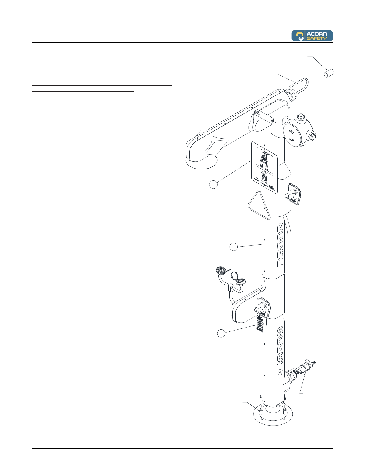
EYE/FACE WASH OPERATION
INSTRUCTIONS:
Maintain and inspect in accordance with ANSI Z358.1-2009
Employees who work with hazardous materials should
become familiar with the location and operation of the
nearest emergency plumbing fixture. Emergency plumbing
fixtures stations are simple to use and require hands free
operation once the station is activated. Regular instruction
regarding proper care and use will increase confidence that
the units are accessible and function properly.
EYE/FACE WASH MAINTENANCE
GUIDE:
2. Remove strainer and washout any debris collected
–replace as required.
The route and area surrounding the Eye Wash should be
clear and unobstructed; the sooner eyes are flushed, the
less likelihood of damage. Eye Wash stations should be
located in close proximity to the hazard and take no more
than 10 seconds to reach. In the case of sever eye
contamination the victim may require assistance to the Eye
Wash station and help flushing their eyes.
Safety plumbing fixture equipment should be operated
weekly for a period long enough to verify operation, clear
the supply line of any sediment build-up and minimize
microbial contamination due to sitting water.
1. To start the Eye Wash, swing spray nozzle assembly over
the basin and push the paddle forward to the horizontal
or fully “ON” position. Flushing should start, popping the
spray nozzle caps open.
3. Using thumb and forefingers, fully open eyelids and flush
eyes thoroughly for approximately 15 minutes or until
medical personnel arrive. Be prepared to let the doctor
know what type of contamination has entered the eye.
Acorn Safety a division of Acorn Engineering Company™
5. Return push paddle to vertical or fully “OFF” position and
swing back to stand by position. To prevent Eye Wash
spray nozzles from becoming contaminated, always
close nozzle lids after each use.
4. While in operation, inspect spray nozzles for clogs or
debris correct or replace as required.
3. Operate Eye Wash nozzles using the push paddle to
place ball valve in the fully “ON” position checking for
smooth operation of valve push paddle mechanism at the
same time ensuring that the Eye Wash spray nozzle caps
pop off immediately when actuated. If the ball valve does
not operate smoothly check the actuating assembly for
binding or missing parts. If the Eye Wash spray nozzle
caps do not pop off immediately when actuated check for
correct supply inlet pressure.

Installation & Operation Manual
Manual #7109-208-001 Revised: 11/12/18
Page 10 of 11
Acorn Safety a division of Acorn Engineering Company™
1
2
3
4
5
6
7
8
9
10
29
28
27
26
23
22
21
9
20
19
18
17
16
15
14
13
12
25
11
24

ITEM # PART NUMBER DESCRIPTION
1 7106-191-000 HOUSING, UPPER, LEFT HAND, HEAT TRACED
2 7106-311-000 TRIM, RUBBER U SHAPE
3 0124-054-000 SCREW, #8-18X1/2", BUTTON HD, SS, THRD FORMING
4 7102-300-001 ASSEMBLY, PLASTIC SHOWER HEAD
5 7101-104-001 FACEWASH ASSY
6 7101-403-000 STAINLESS STEEL YOKE SUPPLY TUBE
7 7101-401-199 STAINLESS STL YOKE FTG, INTERNAL THRDS
87106-349-000 3/8" BENT SPLY TUBE, E/F, S/S, HT TRACE
9 7106-304-000 GROMMET 1.13 OD .81 ID .38 THK HT TRACE
10 7106-192-000 HOUSING, LOWER, LEFT HAND, HEAT TRACED
11 7106-412-000 HOSE EPDM RUBBER MULTI-PURPOSE HT TRACE
12 7100-401-000 EYE/FACE WASH SERVICE TAG
13 0304-008-000 3/8 -16 ZINC PLATED NUT
14 7100-400-000 PUSH HANDLE LABEL
15 7106-407-199 ACTIVATOR PUSH HANDLE, HT TRACE
16 7100-325-000 S/S 1 1/4"x1/2 NPT REDUCING BUSHING
17 1974-001-000 1/2"-14x1.5"L GALV NPT NIPPLE
18 7100-312-000 1/2 ANTI-FREEZE VALVE
19 1895-550-000 1/2" NPTx1/2"ID TUBE BARBED
20 7106-193-000 HOUSING, LOWER, RIGHT HAND, HEAT TRACED
21 7102-350-000 PULL HANDLE, DRENCH SHOWER, 29"
22 7106-207-000 4 HUB 1-1/4 w/ 3/4 SEAL FITTING w/NIPPLE
23 7100-128-000 1-1/4" NPT GALVANIZED PLUG
24 7106-200-000 1-1/4 X 3/4 REDUCING BUSHING
25 7106-302-000 GROMMET 1.75 OD 1.00 ID .50 THK HT TRACE
26 7102-352-150 HANDLE BRACKET, EXTENSION, PULL ROD
27 7100-219-000 WASHER, NYLON, OD.5 X ID.25 X THICK .15
28 0341-103-000 COTTER PIN, HAIRPIN, 1 1/8 LG. .059 DIA. WIRE, STN. STL.
29 7106-191-000 HOUSING, UPPER, RIGHT HAND, HEAT TRACED
Table of contents
Other Acorn Safety Bathroom Fixture manuals
Popular Bathroom Fixture manuals by other brands

Hans Grohe
Hans Grohe ShowerSelect S 15747000 Instructions for use/assembly instructions

Axor
Axor Starck 12452009 Instructions for use/assembly instructions

Symmons
Symmons Winslet S-5104-TRM Operation & maintenance manual

TESA
TESA POWER.KIT BK30-2 installation guide

Arrow
Arrow Free 5201-95 installation manual

Nadoli
Nadoli DSR543648C-CL manual

sanindusa
sanindusa sanlife Assembly and use instructions

Symmons
Symmons Canterbury S-264-2 Installation and service instructions

Kohler
Kohler SKYLINE K-705876T-FM-SHP installation instructions

Fontaine
Fontaine S-2612 installation manual

Signature Hardware
Signature Hardware ROMAN TUB FAUCET 448005 quick start guide

Axor
Axor Citterio 39440009 Installation