Acorn Safety S0000-AL3 Manual

TECHNICAL ASSISTANCE TOLL FREE TELEPHONE NUMBER
1.800.591.9360
TECHNICAL ASSISTANCE FAX: 1.626.855.4894
WWW.ACORNSAFETY.COM
INSTALLATION, OPERATION AND MAINTENANCE INSTRUCTIONS
P.O. BOX 3527
CITY OF INDUSTRY, CA 91744-0527
UNITED STATES OF AMERICA
ACORN SAFETY
Models S0000-AL3
LIMITED WARRANTY
UNITED STATES AND CANADA
Acorn Safety warrants that its products are free from defects in material or workmanship under normal use and
service for a period of one year from date of shipment. Acorn's liability under this warranty shall be discharged solely
by replacement of repair of defective material, provided Acorn is notified in writing within one year from date of
shipment, F.O.B. Industry, California.
This warranty does not cover installation or labor charges and does not apply to materials, which have been
damaged by other causes such as mishandling or improper care or abnormal use. The repair or replacement of the
defective materials shall constitute the sole remedy of the Buyer and the sole remedy of Acorn under this warranty.
Acorn shall not be liable under any circumstances for incidental, consequential or direct charges caused by defects in
materials, or any delay in the repair or replacement thereof. This warranty is in lieu of all other warranties expressed
or implied. Product maintenance instructions are issued with each unit and disregard or non-compliance with these
instructions will constitute an abnormal use condition and void the warranty. Stainless steel must be protected on job
sites during construction and must be properly maintained after the water has been introduced into the safety product
or Acorn's warranty is void.
3. Check your installation for compliance with plumbing, electrical, ANSI Z358.1 and
other applicable codes.
1. Please leave this documentation with the owner of the fixture when finished.
2. Please read this entire booklet before beginning the installation.
NOTES TO THE INSTALLER:
Acorn Safety a division of Acorn Engineering
Manual #7109-305-001 Revised: 12/10/18

Installation & Operation Manual
1. Read the installation instructions prior to beginning the installation.
2. Separate parts from packaging and verify all necessary parts are accounted for and undamaged. Obtain missing or
damaged parts from Acorn Safety prior to beginning installation.
4. In order to comply with ANSI Z358.1, the safety equipment must be inspected periodically. An inspection tag is provided for
documentation purposes.
5. All employees at risk of contamination should be informed and trained in the use of this and any other safety equipment.
The signage provided should be posted appropriately in close proximity to this equipment.
PRELIMINARY STEPS
3. Flush water supply lines prior to installation. This will remove unwanted debris from the lines and prevent unwanted
blockages in the safety equipment.
Page 2 of 9
Acorn Safety a division of Acorn Engineering
Manual #7109-305-001
ROUGH-IN
S0000-AL3 FLUSH MOUNT
51
2" SQ.
(140)
HANGER
PLATE
AMBER STROBE
1 FLASH PER SECOND
ALARM HORN
90 dB AT 10 FEET
21
2" (65)
47
8" (125)
5
8" (15)
J-BOX & J-BOX EXTENSION
BY OTHERS
6" MIN
[150]
6" MIN
[150]
125 / 250VAC, 5A DPDT
DOUBLE POLE, DOUBLE
THROW FLOW SWITCH
GENERAL NOTES:
1. ALL DIMENSIONS ARE IN INCHES [MM].
2. FLOW SWITCH SHALL BE INSTALLED VERTICALLY WITH HORIZONTAL FLOW.
3. DIRECTION OF WATER FLOW MUST BE IN SAME DIRECTION AS SHOWN ON FLOW SWITCH.
4. J-BOX AND J-BOX EXTENSION BY OTHERS.
UNIONS & PIPE
SUPPLIED BY OTHERS
FLOW
12"
[305]
3
4" NPTI CONDUIT
CONNECTION
FLUSH MOUNTING
KEEP SWITCH
BODY VERTICAL
HORN / STROBE
ASSEMBLY
Revised: 12/10/18

Installation & Operation Manual
Page 3 of 9
Acorn Safety a division of Acorn Engineering
Manual #7109-305-001
S0000-AL3 SURFACE
MOUNT
ROUGH-IN
6" SQ.
[150]
AMBER STROBE
1 FLASH PER SECOND
ALARM HORN
90 dB AT 10 FEET 21
2" [65]
47
8" [125]
5
8" [15]
ALARM
BOX
31
2"
[90]
11
4"
[30]
6" [150]
SQ
HANGER PLATE
6" MIN
[150]
6" MIN
[150]
125 / 250VAC, 5A DPDT
DOUBLE POLE, DOUBLE
THROW FLOW SWITCH
GENERAL NOTES:
1. ALL DIMENSIONS ARE IN INCHES [MM].
2. FLOW SWITCH SHALL BE INSTALLED VERTICALLY WITH HORIZONTAL FLOW.
3. DIRECTION OF WATER FLOW MUST BE IN SAME DIRECTION AS SHOWN ON FLOW SWITCH.
4. J-BOX AND J-BOX EXTENSION BY OTHERS.
UNIONS & PIPE
SUPPLIED BY OTHERS
FLOW
12"
[305]
3
4" NPTI CONDUIT
CONNECTION
SURFACE MOUNTING
TOP & BOTTOM
1
2" NPT x 1
2" DRIVE,
BOX PLUGS
KEEP SWITCH
BODY VERTICAL
HORN / STROBE
ASSEMBLY
Revised: 12/10/18

Installation & Operation Manual
Page 4 of 9
Manual #7109-305-001
Acorn Safety a division of Acorn Engineering
ELECTRICAL WIRING
S0000-AL3
WIRE AND
CONNECTORS
BY OTHERS
WIRE AND CONNECTORS BY
OTHERS
EXISTING WIRES
NOTES:
NC
WHITE
BLACK
BLACK
BLACK
NO
C
GREEN
WHITE
BLACK
TOP
LIGHT
SIGNAL
LIGHT
SIGNAL
GREEN
HORN / STROBE
ASSEMBLY
BACK
FLOW
SWITCH
FLOW SWITCH
JUNCTION BOX
4" J-BOX w/ EXTENSION OR
ALARM BOX
Revised: 12/10/18

Installation & Operation Manual
Page 5 of 9
Manual #7109-305-001
Acorn Safety a division of Acorn Engineering
S0000-AL3-ASW
ELECTRICAL WIRING
WIRE AND
CONNECTORS
BY OTHERS
WIRE AND CONNECTORS BY
OTHERS
EXISTING WIRES
NOTES:
NC
WHITE
BLACK
BLACK
BLACK
NO
C
FLOW
SWITCH
GREEN
WHITE
BLACK
TOP
LIGHT
SIGNAL
LIGHT
SIGNAL
GREEN
HORN / STROBE
ASSEMBLY
BACK
RED
RED
SILENCING
SWITCH
FLOW SWITCH
JUNCTION BOX
4" J-BOX w/ EXTENSION OR
ALARM BOX
Revised: 12/10/18

Page 6 of 9
Acorn Safety a division of Acorn Engineering
Installation & Operation Manual
Manual #7109-305-001
Notes:
lDO NOT connect AC power to the alarm until
directed to in these installation instructions to
reduce the risk of shock.
lDO NOT tamper with this device when the
signal circuit is energized. Disconnect power
and wait at least 5 minutes for stored energy to
dissipate before handling to reduce the risk of
shock.
1. UL building wire to make connections from flow
switch, alarm (light / horn) and electrical service.
2. Piping, unions or other connections to meet
required minimum distances for flow switch.
3. 4" x 4" x 2-1/8" J-box and 1-1/2" J-box
extension for adapting alarm for flush mounting
to finished wall.
IMPORTANT: FLUSH WATER SUPPLY LINES
PRIOR TO CONNECTION TO SAFETY
EQUIPMENT.
lFlow Switch must be installed with tee fitting in
horizontal position, switch body in vertical
position (as shown on page 3) and at least 6”
from closest fitting.
lFlow Switch direction of flow is indicated on
switch body.
SUPPLIES REQUIRED:
(not provided by Acorn)
lUse hand tools and wrenches in a manner
which will prevent marring finished surfaces.
Strap wrenches or tools with plastic jaw linings
are highly recommended.
lRefer to fixture rough-in information for location
of supply lines.
4. Surface mounting may require wall anchors and
anchoring hardware for wall mounting alarm
box.
lFragments of Teflon tape or pipe sealant residue
can interfere with the proper operation of this
unit. Ensure pipe sealant methods do not cause
contamination in the system.
WARNINGS:
5. Pipe sealant or Teflon tape for sealing water
connections.
1-1/4" NPT TEE
CONNECTIONS
1-1/4" NPT x 1" NPT
ADAPTERS PROVIDED
3
4" NPT FOR CONDUIT
BY OTHERS
½" NPT TEE
CONNECTIONS
3
4" NPT FOR CONDUIT
BY OTHERS
FLOW SWITCH
JUNCTION COVER
FLOW SWITCH
BODY
FLOW SWITCH
BODY
DIRECTION OF FLOW
INDICATOR IS NOT
EASY TO SEE
FLOW SWITCH
JUNCTION COVER
DIRECTION OF FLOW
INDICATOR IS NOT
EASY TO SEE
S0000-AL3
S0000-AL3-FLW2
1
2" NPT x 3
8" NPT
ADAPTERS PROVIDED
Revised: 12/10/18

Page 7 of 9
Acorn Safety a division of Acorn Engineering
Manual #7109-305-001
Installation & Operation Manual
4. Connect the ground wires and ground in
accordance of local and NEC National Electrical
Code requirements. A green ground screw is
provided on the alarm box (or J-box).
STEP ONE:
FLOW SWITCH INSTALLATION
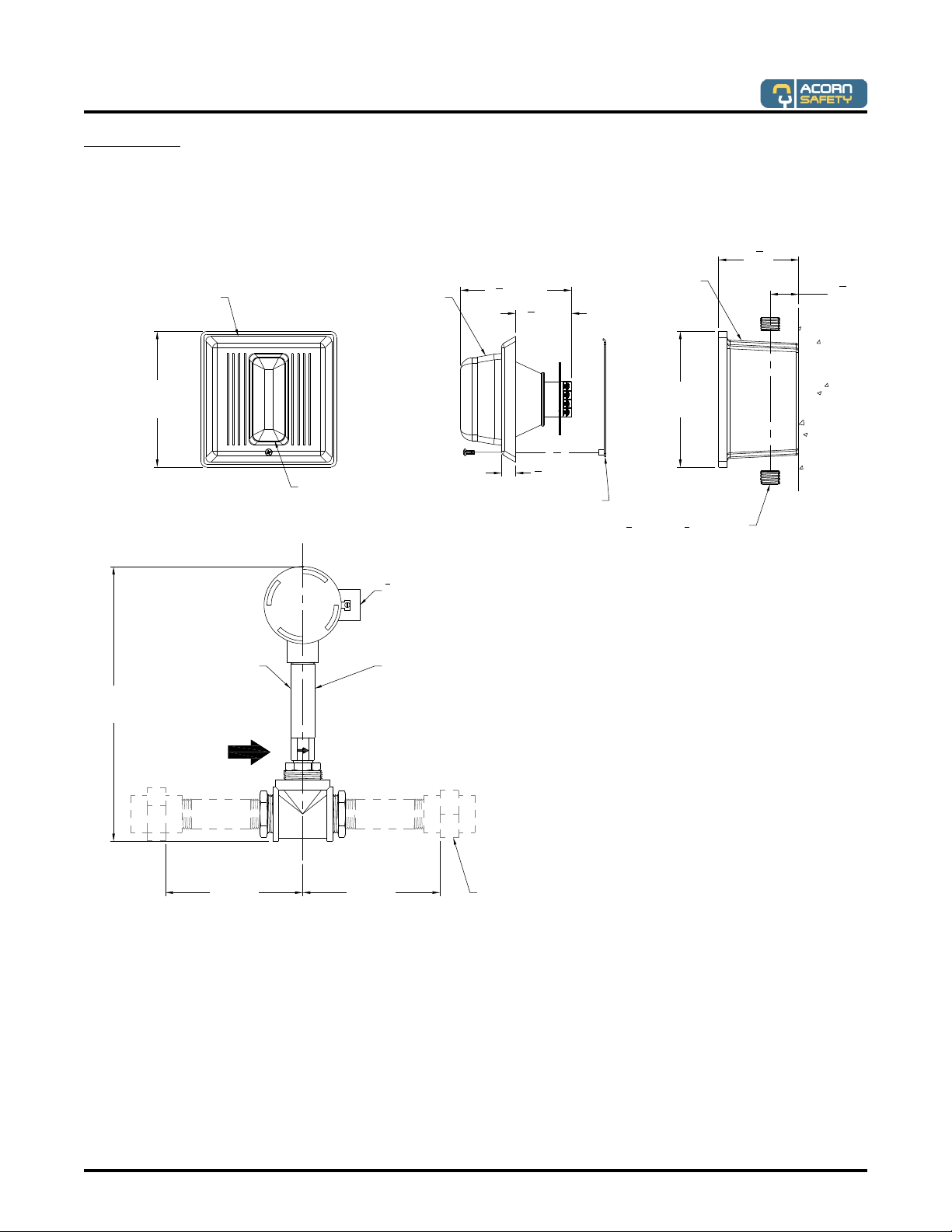
1. Determine location of flow switch in water
supply line. The inlet and outlet ports of the flow
switch must be a minimum of 6” from any tees
or elbows (as shown on page 3) in the water
supply line. Refer to page 6 and rough-in
drawing.
2. Pipe the flow switch in-line of fixture supply
inlet. The switch body must be in the vertical
position with the water pipe horizontal. The
water flow must be in the direction of the arrow
that is marked on the flow switch body. Refer to
page 6 and rough-in drawing.
STEP TWO:
ALARM INSTALLATION
2.Attach alarm hanger plate as shown with angled
flange in an upward orientation.
1. Determine mounting method and location of
alarm. As a recommendation, locate the alarm
near emergency equipment and in a manner
that would allow it to be readily visible by
employees and quick reaction or emergency
personnel when activated.
3. Connect wiring (supplied by others) to the
terminals within the flow switch junction box as
shown in the appropriate wiring diagram. Extra
set of wiring terminals provided for remote
monitoring, not shown.
3. Field wire flow switch to alarm box (or J-box).
Provide electrical service wiring to alarm box (or
J-box). Note: Circuit wiring should not be
energized at this time. It is recommended that
the alarm and other components be installed in
accordance of national and local electrical
codes.
5. Connect flow switch field wiring and electrical
service wiring to alarm terminals as indicated in
wiring diagram.
6. Hang the horn/strobe assembly over the hanger
plate with the mounting screw at the bottom,
then tighten mounting screw to secure..
7. Apply power to the circuit and test to verify
operation.
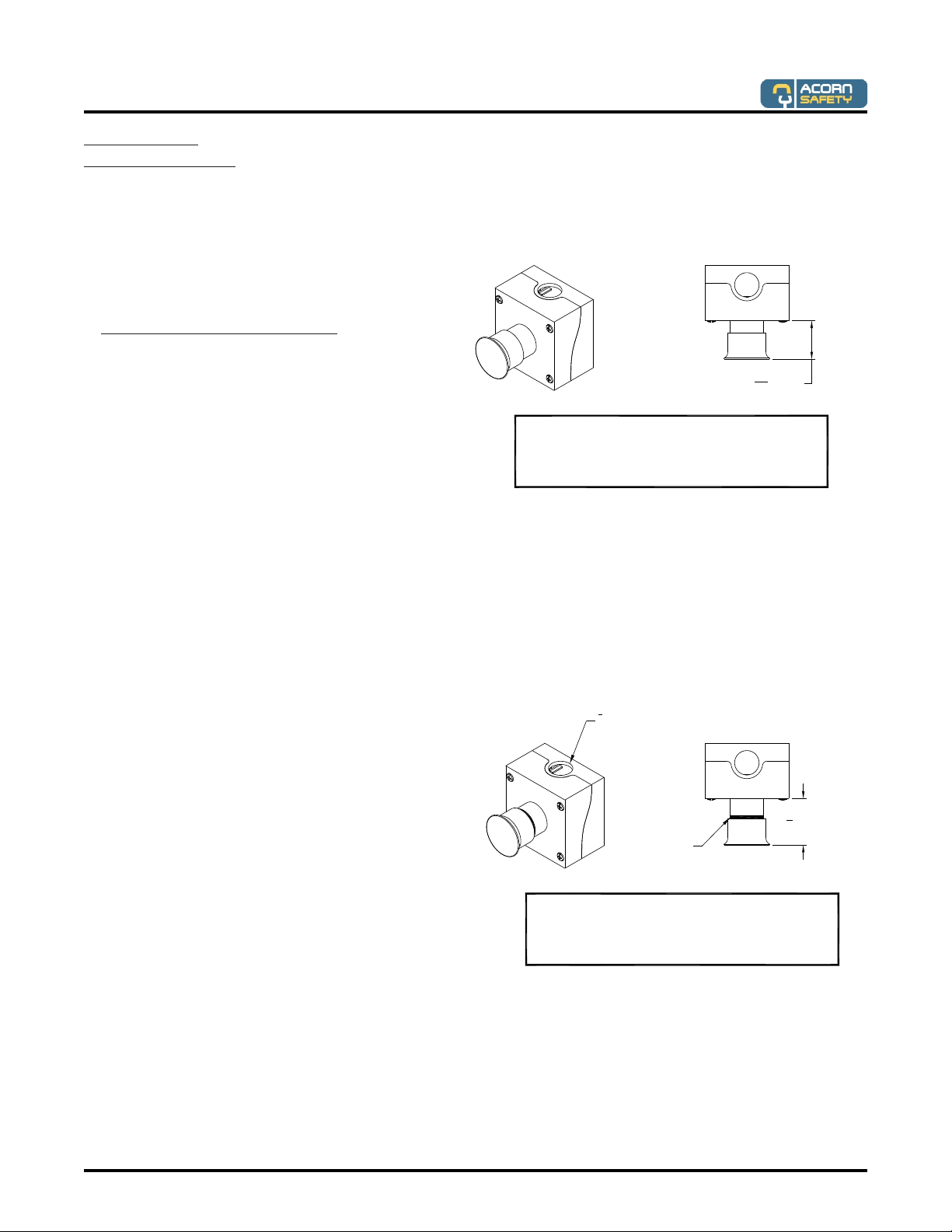
SURFACE MOUNTING J-BOX
(NTS)
2" [51]
3"
[76]
1
2" NPT REMOVABLE
BOX PLUGS
#10 x 1-1-4" LONG PHILLIPS
HEAD SCREWS PROVIDED
CAP PLUGS
PROVIDED
Ø1
4" [6.3] FIELD
DRILLING REQUIRED
2" [51]
11
2"
[38]
HANGER PLATE
HORN / STROBE
ASSEMBLY
Revised: 12/10/18

Page 8 of 9
Manual #7109-305-001
Acorn Safety a division of Acorn Engineering
Installation & Operation Manual
STEP THREE:
TEST OPERATION
2. Supply water to fixture and flush air from
system.
4. De-activate safety equipment. Alarm horn and
strobe should now automatically de-activate.
1. Apply power to alarm circuit. Unit should not be
operating if safety equipment is not activated.
3. Activate safety equipment. Alarm horn should
be sounding and strobe light should be flashing.
ASW SILENCING SWITCH ONLY. Test
silencing switch. Push silencing button, while
alarm is active; the horn should stop sounding
and the strobe should continue to flash.
To reset -ASW Silencing Switch: Pull button
firmly, an audible “pop” should be heard and a
yellow band should be visible near the end of
the mushroom button. NOTE: If the yellow band
is not visible, switch is NOT reset and the horn
will not sound the next time alarm is activated.
YELLOW
BAND
15
8" (41)
15
16" (35)
WHEN FULLY EXTENDED, A VISIBLE YELLOW
BAND WILL APPEAR ON THE PUSHBUTTON
SHAFT AT THE REAR OF THE MUSHROOM
PUSHBUTTON.
ALARM SILENCING SWITCH SHOWN
ACTIVATED. TO RESET AFTER SILENCING
ALARM, ASW PUSHBUTTON MUST BE PULLED
FIRMLY TO FULLY EXTENDED POSITION.
1
2" NPT CONDUIT
CONNECTION
Revised: 12/10/18

2
3
4
5
Page 9 of 9
Acorn Safety a division of Acorn Engineering
Installation & Operation Manual
Manual #7109-305-001
PARTS LIST
Revised: 12/10/18
Caution: Replace alarm should the unit fail to
operate. Do not attempt repair.
MAINTENANCE:
Perform visual inspection and an operational test
twice a year.
ITEM PART NUMBER DESCRIPTION
1
7103-115-000
ALARM, AMBER STROBE WITH
HORN
2 7103-102-000 DPDT FLOW SWITCH, ½” NPT
3
7103-104-000
DPDT FLOW SWITCH, 1-1/4” NPT
4 7103-111-001 DPDT FLOW SWITCH, 3/8” NPT
5
7103-110-001
DPDT FLOW SWITCH, 1” NPT
Table of contents