KORPORACJA OLIVIER AKO-52201 User manual

5220H101 Ed.03 GB
Gas leak detection alarm for permanent connection
AKO-52201 AKO-52202 AKO-52210
AKO-52211 AKO-52212
Korporacja Olivier Sp. z o.o. tel. 696 035 469

Table of contents
Chapter 1: Introduction
Chapter 2: Versions and references
Chapter 4: Equipment description
Chapter 3: Warnings
Chapter 5: Installation
Station assembly
Detector assembly
Connection and configuration
Chapter 6: Operation
Chapter 7: Maintenance
Chapter 8: Technical data
Page 3
Page 3
Page 4
Page 3
Page 4
Page 4
Page 5
Page 5
Page 6
Page 6
Page 7
AKO Electromecànica thanks you and congratulates you on the purchase of our product, the development and manufacture of which involved
the most innovative technologies, as well as rigorous production and quality control processes.
Our commitment to achieving customer satisfaction and our continuous efforts to improve day by day are confirmed by the various quality
certificates obtained.
This is a high performance, technologically advanced product. Its operation and the final performance achieved will depend, to a great extent,
on correct planning, installation, configuration and commissioning. Please read this manual carefully before proceeding to install it and
respect the instructions in the manual at all times.
Only qualified personnel may install the product or carry out technical support.
This product has been developed for use in the applications described in the manual. AKO Electromecànica does not guarantee its operation
in any use not foreseen in this document and accepts no liability in the case of damage of any type which may result from incorrect use,
configuration, installation or commissioning.
Complying with and enforcing the regulations applying to installations where our products are destined to be used is the responsibility of the
installer and the customer. AKO Electromecànica accepts no liability for damage which may occur due to failure to comply with these
regulations. Rigorously follow the instructions described in this manual.
In order to extend the lifetime of our products to the maximum, the following points must be observed:
Do not expose electronic equipment to dust, dirt, water, rain, moisture, high temperatures, chemical agents or corrosive
substances of any type.
Do not subject equipment to knocks or vibrations or attempt to handle them in any way differently to that indicated in the manual.
Do not under any circumstances exceed the specifications and limitations indicated in the manual.
Respect the indicated environmental conditions for operation and storage at all times.
During installation and on completion of this, avoid the presence of loose, broken or unprotected cables or cables in poor
condition. These may constitute a risk for the equipment and its users.
AKO Electromecànica reserves the right to make any modification to the documentation and the product without prior notification.
2
Korporacja Olivier Sp. z o.o. tel. 696 035 469

1.- Introduction
Refrigerator gas leak detection alarm to be used in refrigerated facilities designed to comply with standard
EN 378-3.
2.- Versions and references
WARNINGS
* The pre-alarm and alarm levels can slighty differ from the values shown in the table depending
on the detected type of gas.
- The alarm and detectors should be installed in a place protected from vibrations, water and corrosive
gases, where the ambient temperature does not exceed the value indicated in the technical data. The
station should be installed in a place where the regular presence of people who can alert to the
presence of alarms is guaranteed.
- To prevent false alarms, the detector should be installed away from:
Maintenance rooms where solvents, paints or refrigerator gases are handled.
Ÿ
Fruit ripening or storage rooms, as some fruits can emit gases.
Ÿ
Smoke outlets located in confined spaces (carbon dioxide, propane, LPG) or from engines,
Ÿ
generators or motorised machinery (fork-lift trucks, etc.).
Particularly damp areas or with the risk of getting wet.
Ÿ
Areas with strong ventilation.
Ÿ
- Do not paint the detector or place it near solvents or paints.
- Neither the alarm or gas detector are suitable for areas classified as potentially explosive.
English
AKO-52202
AKO-52201 AKO-52210 AKO-52211
MODEL
DESCRIPTION
DETECTOR INCLUDED
POWER SUPPLY
AKO-52201
Alarm station + Detector
AKO-52211
90-260V~
50/60 Hz
AKO-52202
Alarm station + Detector
AKO-52212
AKO-52210
Alarm station
-
AKO-52211
Detector for freon gases. Type A
-
-
AKO-52212
Detector for freon gases. Type B
-
DETECTOR
GASES IT DETECTS
PRE-ALARM
ALARM
AKO-52211
R-134a, R-407C, R-410A, R-417A, R-409A, R-32
500 ppm*
1000 ppm*
AKO-52212
R-404A, R-507A, R-22, R-23, R-422D, R-422A, R-434A,
R-437A, R-408A, R-403B, R-124, R-407A
AKO-52212
3
Korporacja Olivier Sp. z o.o. tel. 696 035 469

4.- Equipment description
Alarm station
Mute/reset button
Mutes the alarm or deletes saved alarms
Pre-alarm jumper
It allows deactivating pre-alarm detection.
Before using this option, make sure that
regulations allow for only one alarm level.
Gas detector
Delay switch
It delays the activation of alarms detected in the station.
*Default value.
IMPORTANT: The delay configuration should be carried out with the station's power supply
disconnected, as if not it will not work.
5.- Installation
The wiring between the detector and the station should NEVER be installed
in a conduit together with power, control or feeder cables.
Station assembly
The detector status indicators will indicate the alarms and pre-alarms
immediately, without taking into account the delays.
- Remove the cover T of the equipment (Fig. 1).
- Open the equipment and remove the front of the housing (Fig. 2).
- Drill the holes needed for the cable entry glands using the pre-stamped
centres on the sides of the housing for guidance.
- Drill 3 holes on the wall following the fixing holes 1, 2, 3. (Fig. 3).
- Fasten the glands into the equipment.
- Insert the 3 screws and wall plugs through the housing into the holes in the
wall and tighten.
- Insert the cables through the glands.
- Fit the front of the housing (Fig.2).
- Insert and tighten screws D, F (Fig. 1).
- Connect the cables as shown in the wiring diagram, close the cover T,
insert and tighten screws A, C (Fig. 1).
FIG. 2
FIG. 1
222,1 mm
140 mm
222,1 mm
140 mm
FIG. 3
VISUAL ALARM
ACOUSTIC ALARM
PRE-ALARM JUMPER
MUTE/RESET BUTTON
DETECTOR STATUS
STATUS INDICATORS
POWER SUPPLY STATUS
DELAY SWITCH
Without delay* 30 sec.
60 sec. 120 sec.
Without pre-alarm
With pre-alarm
4
Korporacja Olivier Sp. z o.o. tel. 696 035 469

English
Detector assembly
The detector should be installed in an area where the highest
amount of gas may concentrate, near places where gas leaks
could start and accessible for maintenance work. It is also
advisable to place it away from transit areas or areas where it could be
accidentally knocked.
Different types of gas can have different densities, and this means that
leaks could concentrate in the lowest part of the room or near the roof.
Take this into account when deciding on the height of the detector.
It is advisable to install the freon detectors around 20 cm from the
ground, with an free distance around them of some 50 cm.
- Remove the detector's cover (Fig. 4).
- Drill the hole for the glands needed for the cable entry following the
pre-stamped centres on the bottom or top of the base.
- Drill 3 holes on the wall following the fixing holes. (Fig. 5).
- Fasten the gland onto the base.
- Insert the 3 screws+plugs through the base, into the 3 holes on the
wall and tighten.
- Insert the cables into the gland and connect them according to the
wiring diagram.
- Adjust the alarm/pre-alarm delays using the delay switch (See page 10)
- Insert the cover and gently press it until you hear a “click”.
Wiring
Always disconnect the power supply to do the wiring.
The power circuit should be equipped with a switch for its disconnection of at least 2 A, 230 V, situated
near the appliance. The power supply cable should be H05VV-F or H05V-K type. The gauge will depend on local
2
regulations, but should in no case be less than 1 mm .
Cables for wiring the relay contact should have an adequate section depending on the unit to be connected.
AKO recommends the use of shielded cable for the wiring of the detectors.
Alarm
Output
16A 16A
Pre-alarm
Output
NC NCNO NOC C
-S
+
1L
45
2N +3 6 S -
+12Vcc
Input
90-260 V~
50/60 Hz
GND
Signal
DETECTOR 1
Pre-alarm jumper
Always disconnect the power supply before
changing the position of the jumper.
Max. 50 mts.
Without pre-alarm
With pre-alarm
Status of the relays in the case of
a failure in the electricity supply.
16A 16A
1
45
2 3 6
Fastening
holes
Delay switch
Fastening holes suitable for
universal built-in housing
Press gently
168
125,535
92
60
41,5
Max. Ø 3,7
FIG. 4
FIG. 5
5
Korporacja Olivier Sp. z o.o. tel. 696 035 469

6.- Operation
ALARM STATION
GAS DETECTOR
STATUS
ACOUSTIC
ALARM
RELAYS
Alarm
Pre-
alarm
Delay
Off
Off
Off
Slow flashing
Off
Delayed
pre-alarm
Off
Off
Off
Off
Quick flashing
Pre-alarm
Flashing
On
Flashing
Off
Quick flashing
Delayed
alarm
Flashing
On
Flashing
Off
On
Alarm
Flashing
On
Two-tone sound
Off
On
Saved alarm /
pre-alarm
Off
Flashing
Off
Slow flashing
Off
Detector /
wiring fault
On
On
3 short tones
every 2 minutes
Flashing / alternative
Without
power supply
Off
Off
Off
Off
Off
1
45
2 3 6
A
B
C
D
E
F
1
45
2 3 6
1
45
2 3 6
1
45
2 3 6
1
45
2 3 6
1
45
2 3 6
1
45
2 3 6
*
GAS concentration (ppm)
t
Pre-alarm
level
Alarm level
AB B
C C CD DE EF F
** If during the delay time of a pre-alarm the gas concentration increases to the alarm value, for safety reasons,
the pre-alarm delay will be cancelled, activating the signalling in the station.
*Saved alarm / pre-alarm
They let us check if any alarm / pre-alarm has triggered during our absence.
Mute/reset button
During an alarm, it silences the acoustic alarm, in delay (without alarm), deletes the
existing saved alarms.
**
1
45
2 3 6
6
Korporacja Olivier Sp. z o.o. tel. 696 035 469

Detector heating time
After receiving the electrical power supply, the gas detector needs a heating time of around 5 minutes,
during which it will NOT detect leaks. This time is indicated by means of a quick flashing of the green led
on the detector itself.
Self-diagnosis function
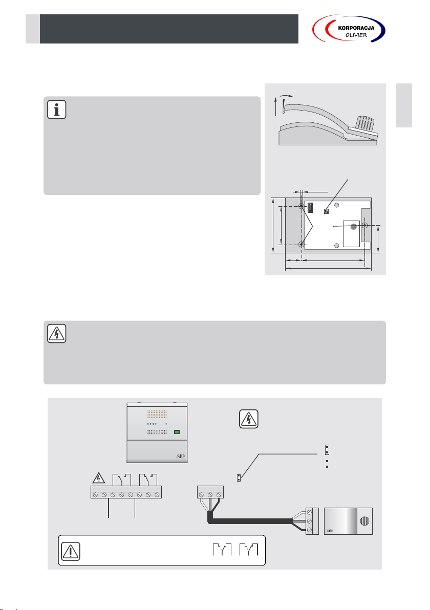
The unit incorporates a self-diagnosis system of the detector and the wiring between the detector and alarm station.
In the case of malfunction, the station will alert making three consecutive tones every 2 minutes, and activating the
visual alarm and the detector status led, while the detector will alternately activate its status leds.
AKO-52210
AKO-52211/52212
7.- Maintenance
Power supply ........................................................................................................................90-260 V~ 50/60 Hz
Maximum input power ................................................................................................................................10 VA
No. of inputs.......................................................................................................................................................1
Compatibility of inputs ......................................................................................Only AKO-52211/52212 detectors
Alarm / pre-alarm relay ...........................................................................................SPDT 230 Vac, 16 A, cos j =1
Working ambient temperature ..........................................................................................................0 ºC to 50 ºC
Storage ambient temperature ........................................................................................................-30 ºC to 70 ºC
Protection degree .........................................................................................................................................IP 40
Installation category ....................................................................................................................II s/ EN 61010-1
Pollution degree ..........................................................................................................................II s/ EN 61010-1
Double isolation between power supply, secondary circuit and relay output.
Sound power..........................................................................................................................90 dB(A) at 1 metre
EMC Standard.......................................................................................................................................EN 61000
Power supply..................................................................................................................................15 Vdc ±3 Vdc
Consumption Typical................................................................................................................................75 mA
Maximum.........................................................................................................................100 mA
Working ambient temperature.......................................................................................................-20 ºC to 50 ºC
Storage ambient temperature ........................................................................................................-20 ºC to 60 ºC
Range of maximum allowed humidity .............................................................5 - 85% RH (without condensation)
Protection degree .........................................................................................................................................IP 40
Life...................................................................................Depending on the temperature and humidity conditions
EMC Standard.......................................................................................................................................EN 61000
ŸClean the surface of the equipment with a soft cloth, water and soap.
ŸDo not use abrasive detergents, petrol, alcohol or solvents, as this might damage the sensor.
ŸAKO guarantees the correct operation of the detectors during the first 3 years from the date of purchase,
and after this time, it is advisable to replace the detector.
ŸWe recommend changing the detector in the event of having been exposed to high gas concentrations.
The correct operation of the detector should be checked at least once a year, ask about if
your current local regulations require lower intervals.
This check consists of exposing the detector to a small gas concentration and check that
all the relay indications and outputs work correctly.
8.- Technical data
English
7
Korporacja Olivier Sp. z o.o. tel. 696 035 469
This manual suits for next models
4
Table of contents