Acorn BBC Master Series User manual

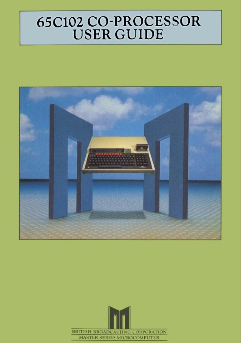
BBC Master
128
SERVICE MANUAL
© 1985 Acorn

British Broadcasting Corporation
Master Series Microcomputer
Service Manual


British Broadcasting Corporation
Master Series Microcomputer
Service Manual
Part No 0443,004
Issue 1
April 1986


Master Series Service Manual
Within this publication the term 'BBC' is used as an abbreviation for
'
British Broadcasting Corporation'.
Copyright Acorn Computers Limited 1986
Neither the whole or any part of the information contained in, or the
product described in, this manual may be adapted or reproduced in any
material form except with the prior written approval of Acorn
Computers Limited (Acorn Computers).
The product described in this manual and products for use with it, are
subject to continuous development and improvement. All information of
a technical nature and particulars of the product and its use (
including the information and particulars in this manual) are given by
Acorn Computers in good faith. However, it is acknowledged that there
may be errors or omissions in this manual. A list of details of any
amendments or revisions to this manual can be obtained upon request
from Acorn Computers Technical Enquiries. Acorn Computers welcome
comments and suggestions relating to the product and this manual.
All correspondence should be addressed to:-
Technical Enquiries
Acorn Computers Limited
Newmarket Road
Cambridge
CB5 8PD
All maintenance and service on the product must be carried out by
Acorn Computers' authorised dealers. Acorn Computers can accept no
liability
whatsoever for any loss or damage caused by service or
maintenance by
unauthorised personnel. This manual is intended only to
assist the reader in the use of this product, and therefore Acorn
Computers shall not be liable for any loss or damage whatsoever
arising from the use of any information or particulars in, or any
error or omission in, this manual, or any incorrect use of the
product.
This manual is for the sole use of Acorn Computers' authorised dealers
and must only be used by them in connection with the product described
within.
First published 1986
Published by Acorn Computers Limited
1
Issue 1

Master Series Service Manual
WARNING: THE COMPUTER MUST BE EARTHED
IMPORTANT: The wires in the mains lead for the apparatus are coloured in
accordance with the following code:
Green & Yellow Earth
Blue Neutral
Brown Live
The moulded plug must be used with the fuse and fuse carrier firmly in place.
The fuse carrier is of the same basic colour (though not necessarily the same
shade of that colour) as the coloured insert in the base of the plug.
Different manufacturers' plugs and fuse carriers are not interchangeable. In
the event of loss of the fuse carrier, the moulded plug MUST NOT be used.
Either replace the moulded plug with another conventional plug wired as
detailed below, or obtain a replacement fuse carrier from an authorised Acorn
dealer. In the event of the fuse blowing it should be replaced, after
clearing any faults, with a 3 amp fuse that is ASTA approved to BS1362.
If the socket outlet available is not suitable for the plug supplied, the
plug should be cut off and the appropriate plug fitted and wired as
previously noted. The moulded plug which was cut off must be disposed of as
it would be a potential shock hazard if it were to be plugged in with the cut
off end of the mains cord exposed.
As the colours of the wires may not correspond with the coloured markings
identifying the terminals in your plug, proceed as follows:
The wire which is coloured green and yellow must be connected to the terminal
in the plug which is marked by the letter E, or by the safety earth symbol -
I-, or coloured either green or green and yellow.
The wire which is coloured blue must be connected to the terminal which is
marked with the letter N, or coloured black.
The wire which is coloured brown must be connected to the terminal which is
marked with the letter L, or coloured red.
2 Issue 1

Master Series Service Manual
BBC Master Series Microcomputer Service Manual
Contents
1 - Introduction
2 - Packaging and installation
3 - Disassembly and assembly
4 - Selection links
5 - Hardware description
5.1 Introduction
5.2 Core machine
5.3 Internal I/O
5.4 External I/O
6 - Test equipment
7 - Fault finding
7.1 Switch on
7.2 Sideways RAM
7.3 Video
7.4 Real time clock
7.5 Analogue port
7.6 RS423 port
7.7 Cassette interface
7.8 Disc drive interface
7.9 Parallel printer port
7.10 User port
7.11 1MHz bus
7.12 The Tube
7.13 Internal co-processor
7.14 Sound output
7.15 Modem connector
7.16 Cartridge port
7.17 Econet
Appendix
Connector pinouts
Parts list
Component locations
PCB circuit diagram
Final assembly
EPROM cartridge circuit diagram
Econet module circuit diagram
Keyboard circuit diagram
3 Issue 1

Master Series Service Manual
1 Introduction
This manual is intended to provide the information required to
diagnose and repair faults on the BBC Master Series Microcomputer
which was designed by Acorn Computers Ltd of Cambridge, England.
The information contained in this manual is aimed at service engineers
and Acorn dealers who will be servicing the BBC Master Series
Microcomputer on behalf of Acorn Computers Ltd.
4
Issue 1

Master Series Service Manual
2 Packaging and installation
The microcomputer is supplied with three-part moulded polystyrene
packing in a cardboard box. Supplied with the microcomputer is a
Welcome Guide, an aerial lead, a welcome tape, a welcome disc, two
reversible keyboard inserts, a VIEW reference card, a ViewSheet
reference card, and a guarantee card.
The mains supply for UK models is 240V AC 50Hz. The microcomputer is
supplied with a moulded 13 amp square pin plug. If this plug is
unsuitable then it must be cut off and thrown away. Instructions for
fitting a replacement plug are given right at the front of this
manual.
The microcomputer is turned on by a switch at the back of the
microcomputer
next to the mains lead.
Do not use the microcomputer in conditions of extreme heat, cold,
humidity or dust or in places subject to vibration. Do not block
ventilation under or behind the computer. Ensure that no foreign
objects are inserted through any openings in the microcomputer
.
5
Issue 1

Master Series Service Manual
3 Disassembly and assembly
To service the BBC Master Series Microcomputer, first disconnect the
power supply plug from the mains and remove all peripheral connections
from the computer.
To disassemble
The lid of the microcomputer case may be removed after undoing the
four fixing screws underneath the case. DO NOT remove the lid with the
mains
power connected.
Inside the microcomputer are four main sub-assemblies:
keyboard
speaker and battery unit (the cartridge nest)
power supply unit
main printed circuit board
To remove the keyboard, first unplug the 2 keyboard connectors from
the main printed circuit board. Undo the 3 screws holding the keyboard
to the case
bottom, and the 1 screw which holds it to the power supply
unit.
To remove the speaker and battery unit, simply lift the casing upwards
and then unplug the two connectors joining it to the board.
The power
supply unit is connected to the main circuit board by seven
push-on connectors which must be unplugged. Three screws on the
underside of the case are undone allowing the unit to be removed. On
reassembly, ensure that the same type of screw is used (M3x6mm).
The main printed circuit board is removed complete with the metal
back-plate. To remove the main printed circuit board, undo the 4
fixing screws which pass through the cartridge connectors into the
case bottom, and the 1 screw which holds the metal back-plate to the
power supply unit. Remove the circuit board from the case by lifting
it slightly at the rear and then sliding it backwards.
To reassemble
Replace the main printed circuit board by putting the front edge (with
connector headers) in first and pulling it forwards until the metal
back-plate drops in. Make sure that all the lugs on the lower case
locate with all the correct points on the PCB and back-plate. Replace
the 4 PCB fixing screws which pass through the cartridge connectors,
and the single screw which joins the back-plate to the power supply
unit.
Reconnect the power supply, being careful to route the wires neatly,
and connect the wires (seven) to the push-on connectors on the PCB,
being very careful to get the polarity right.
PCB connectors marked +5V must have a red wire attached (three)
PCB connectors marked OV must have a black wire attached (three).
The connector marked -5V has the purple wire attached (one).
6
Issue 1

Master Series Service Manual
Replace the speaker and battery unit, first plugging the two
connectors into their correct positions on the board, the battery
connector to PL8 either way round, and the speaker connector to PL9
either way round. Note that although the battery connector can be
plugged either way round, it must locate on all three pins or the
polarity will be wrong. Check carefully.
Replace the keyboard. Replace the 4 screws, 3 to the lower case and 1
to the power supply unit. Be careful to reconnect the keyboard ribbon
sockets so that all the pins are engaged; it is easy to displace the
connectors one pin to right or left.
Make one final check that all reconnections have been made correctly,
especially the power supplies which will short circuit if any two are
reversed.
Replace the lid, and insert and tighten the four fixing screws.
7
Issue 1

Master Series Service Manual
4 Selection links
LK1 PCB track, made A: 1MHz Bus Audio Input/Output
2 position link.
In the-A position the 1MHz Bus signal is an input to the computer's
audio mixer.
In the B position the 1MHz Bus signal is an output from the computer's
audio circuit (Minimum load 1k ohm).
This link is a permanent track in the A position. The track must be
cut before a wire link is used to make the B position.
LK2 PCB track, made: Cartridge -5V
decoupler. One position link.
In some instances, particular cartridge hardware may need a -5V supply
that is decoupled from the main computer -5V load. To do this R9 needs
to be fitted and LK2 which is a track on the circuit board should be
cut.
LK3 : Not present.
LK4 plug, made: Clock chip IRQ.
One position link.
The 6818 clock/RAM chip has a daily alarm function built in. When the
alarm is triggered, the CPU is interrupted via its IRQ line. Removing
the shunt from LK4 disconnects the CPU IRQ line to the clock line.
This function is not supported by the operating system as this feature
may not be present in future versions of the circuit board.
Consequently the clock chip must be
directly operated by the
application software.
LK5 PCB track, made East: CSYNC
polarity.
Two position link.
The polarity of the composite synchronisation signal is determined by
this link. It is supplied as a track on the PCB causing negative
synchronisation polarity. This track must be broken and a piece of
wire used to make the other side of the link for positive
synchronisation.
8
Issue 1

Master Series Service Manual
LK6(0) and LK6(1) plug, made A B: Main Clock Select.
Multi-function link.
This group of 4 pins can take either one or two shorting plugs as
follows:
Link between A and B - The computer main 16MHz reference is provided
by on-board circuitry. This is normally how computers are shipped.
Link between B and D - The computer main 16 MHz reference must be
provided from pin A17 on either of the cartridge connectors. Note that
in this case a clock source MUST be provided or the dynamic memories
could be destroyed.
Link between C and D - The cartridges are clocked by the 8 MHz signal
from the computer. This is a synchronous signal with the 2 MHz (phi2)
signal, also supplied to the cartridges. Note that the link between A
and B must also be fitted.
LK7 PCB track, made East: Video
polarity.
Two position link.
The polarity of the video RGB signals is determined by this link. It
is supplied as a track on the bottom of the PCB causing true polarity.
This track must be broken and a piece of wire used to make the link
West for negative polarity.
LK8 : Not present.
LK9 : Not present.
LK10 fitted for NTSC only: Channel Select.
Two position link.
When used with NTSC VHF televisions, the modulator enables one of two
channels to be selected. Note that the computer as supplied for use in
the UK is fitted with a UHF modulator so LK10 is not fitted.
LK11 : Not present.
LK12 Plug, made B (East): CSYNC/Cartridge Machine
Detect. Two position link.
Position A - This connection to the computer CSYNC line is provided
for GENLOCK purposes.
Position B - Certain hardware cartridges may need to detect whether
they are plugged into a Master Series computer or an Acorn Electron.
Master computers are shipped with this link in the B position, causing
a logic LOW to appear on pin A10 of the cartidges. The Electron has no
connection to this pin.
9
Issue 1

Master Series Service Manual
LK13 PCB track, made West: A to D converter reference select.
Two position link.
As shipped, this link is a track on the bottom of the PCB causing the
A to D converter reference voltage input to be 1.8V.
If the LK13 track is cut then the voltage reference must be applied
between analogue ground and Vref on the external connector.
If the LK13 track is cut and LK13 made East with a wire link, a
precision reference can be fitted in the position PR1 shown on the
circuit diagram.
LK14 PCB track, made: Serial data clock
reference. One position link.
As shipped, this link is a track on the PCB connecting the CHROMA chip
1.23MHz output to the Serial Processor. This link is provided for
production purposes and should not be modified.
LK15 PCB track, made West: PAL/NTSC
select. Two position link.
As shipped in the UK, this link is a track on the bottom of the PCB
causing the CHROMA chip to encode colour information on to the
television output in PAL format. If the track is cut and a wire link
used to make the other side of the link, then colour information will
be encoded in NTSC. In general, televisions within the UK can only
accept the PAL format.
LK16 wire link, not fitted: Chrominance information luma trap
bypass.
One position link.
This link is not normally fitted. It is provided for those
applications where filtering of the luminance information from the
chrominance part of the television signal is not required.
LK17 : Not present.
LK18 plug, made West: Paged ROM/RAM
Select. Two position link.
When fitted in the West position, this link causes 16Kbyte of RAM to
appear
in each of the "sideways" memory "slots" 6 and 7.
When fitted in the East position, a 32Kbyte ROM occupying slots 6 and
7 may be plugged into socket labelled 1C41.
10
Issue 1

Master Series Service Manual
LK19 plug, made West: Paged ROM/RAM Select.
Two position link.
When fitted in the West position, this link causes 16Kbyte of RAM to
appear
in each of the "sideways" memory "slots" 4 and 5.
When fitted in the East position, a 32Kbyte ROM occupying slots 4 and
5 may be plugged into socket labelled IC37.
LK20 : Not present.
LK21 plug, not made: Light Pen Strobe to cartridge.
This link is not normally made, so position B10 on the cartridges is
merely a connection from one to the other. When the shunt is fitted,
the CRTC Light Pen Strobe input is connected to B10. This is to
facilitate GENLOCK and an alternative LPSTB connection to the rear
analogue connector.
11
Issue 1

Master Series Service Manual
5 Hardware description
5.1 Introduction
The Master Series Microcomputer consists of a central processing unit
with associated memory and various input/output devices for
communication with external equipment. Only a fully configured system
will be described here although reference to sub-systems will be made
where relevant.
The Core Machine
All input/output (I/O) computing is performed by a 65C12 CPU with its
principal ancillary components:-
128 Kbyte of Dynamic Random Access memory:- Special expansion options
allow a further expansion of 64 Kbyte. Dedicated hardware can be used
to expand this almost indefinitely.
262 Kbyte of Read Only Memory:- Special expansion options allow a
further expansion of approximately 1/2 Mbyte of ROM. Plug in
cartridges are
available which accept up to 256 Kbyte of ROM.
Internal I/O
Various I/O devices operate solely within the confines of the system
to either improve facilities or increase throughput. These are as
follows:-
6522 VIA devices - Two of these are provided and interface to:-
1)
A 93 contact keyboard with 2 key rollover.
3-Channel sound generator with additional noise
channel. Battery backed up Real-Time Clock and fifty
bytes of RAM.
2)
The Printer Port and User Port
Co-processors
These consist of an additional CPU with associated memory. They have
no I/O capability of their own and depend entirely on the main
processor to supply
such information. They do all the computation not
associated with I/O operations.
When a co-processor is not fitted, the main processor has to perform
both I/O and non I/O computation.
12
Issue 1

Master Series Service Manual
External I/O
Video display:- A 6845 CRT controller is provided to format the output
from ROB, composite video and PAL/NTSC connectors.
Analogue to Digital Converter:- A four channel A-D converter provides
10 bit binary conversions in 5ms. The absolute accuracy will depend on
the conditions of use.
Tape Interface:- Facilities to both save and retrieve data from audio
cassettes is provided.
Disc Interface:- Facilities to both save and retrieve data from
standard Shugart connected media. Filing systems are provided to
support data encoded in FM or MFM.
Network Interface:- Connection to the ECONET is provided by a 68B54
advanced data link controller. This is fitted on a daughter board and
may as such be fitted as an optional extra (standard on the ET
machine).
1MHz Bus:- The standard BBC computer 1MHz bus is provided.
External Second Processor:- An external second processor may be
connected. Selection of either internal co-processor or external
second processor is performed by software. Only one second or co-
processor can be active at a time.
Centronics Printer Port:- Connection is provided for the standard
parallel
printer port configuration.
User Port:- The user port is an eight bit bidirectional bus with two
extra handshaking/serial lines. These are unbuffered.
RS423:- A serial RS423 port is provided.
Audio Output:- The output from the sound generator is amplified to a
speaker and provided at a phono style connector. Sound transfer to and
from the modem is provided.
Modem:- Connection for a modem with both dial pulse and dual tone
multi-frequency dialling is provided. This facility is provided to
support third party hardware.
13
Issue 1

Master Series Service Manual
5.2 Core machine
Operation of the RAM and ROM is controlled by the Memory Controller
integrated circuit. The principal function of this device is to
control the memory paging structure.
Memory Map
The 65C12 can directly address 64K locations. As over 1/2 Mbyte may be
resident (depending on the users configuration), a paging scheme is
implemented to allow access to it.
The basic memory assignment is as follows:
Figure 1
14
Issue 1

Master Series Service Manual
The current memory map is dictated by the contents of the two latches,
ROM SELect and ACCess CONtrol located at &FE30 and &FE34 respectively.
The contents of these two latches are as follows:-
d7 d6 d5 d4 d3 d2 dl d0
(&FE30) RAM 0 0 0
PM3 PM2 PM1 PM0
(&FE34) IRR
TST IFJ ITU
Y X E D
The contents of ROMSEL dictate the selection of memory which resides
from &8000 to &BFFF.
ACCCON
The contents of ACCCON principally dictate the activity of two regions
of memory:
(a) &3000 to &7FFF
(b) &C000 to &DFFF
128 Kbyte RAM
The RAM is functionally split up into two regions: The main region
supports the language workspaces, buffers etc. and provides the bit
mapped screen. The second region provides four, 16K "Sideways" RAM
segments. These are
link selected into ROM locations 4,5,6 and 7. They
may be deselected,
reinstating the ROM sockets in "chunks" of 32
Kbyte.
Within the main 64 Kbyte region, the lower 32K is used within the
&0000 to &7FFF region of the CPU memory map, as shown in figure 1.
The upper 32K is split up into three, self-contiguous regions. The
largest portion of this is a 20 Kbyte region designated LYNNE. This
can be overlayed on the region (a) of main memory.
*
When bit D in ACCCON is set, the CRT controller will display the
contents of LYNNE. When bit D is cleared, the region (a) of main
memory will be displayed.
*
When bit E in ACCCON is set, if the address range is &3000 to &7FFF
the CPU will read/write Lynne according to the flow shown in figure 2.
15
Issue 1
This manual suits for next models
1
Table of contents
Other Acorn Computer Hardware manuals