sparkfun DEV-17272 Technical document

MicroMod Asset Tracker Carrier Board Hookup Guide
Introduction
The MicroMod Asset Tracker Carrier Board provides you with a toolkit to monitor and track the location of your
assets. Do you want to know where your assets are at all times? Or maybe you just want an update if an asset is
moved? If so, this is the product for you!
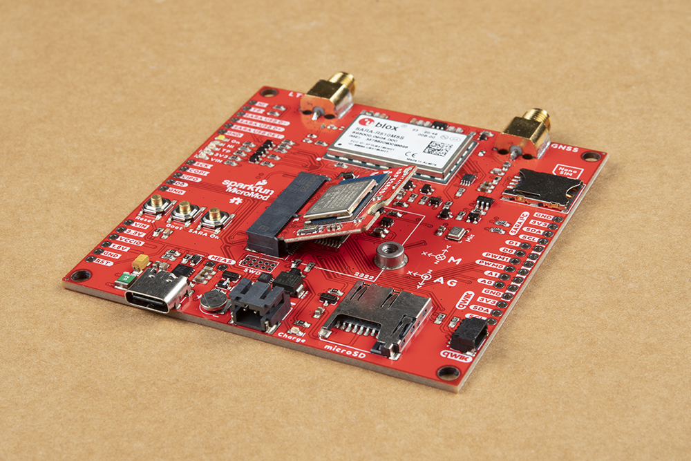
SparkFun MicroMod Asset Tracker Carrier Board
DEV-17272
Product Showcase: SparkFun MicroMod Asset Tracker Carrier BProduct Showcase: SparkFun MicroMod Asset Tracker Carrier B……
Y
O
U
R
A
C
C
O
U
N
T
R
E
G
I
S
T
E
R

Built around the u-blox SARA-R510M8S module, the MicroMod Asset Tracker Carrier Board offers Secure Cloud
LTE-M data communication for multi-regional use and has an integrated u-blox M8 GNSS receiver for accurate
positioning information.
Want to be able to communicate directly with the SARA-R5 over USB-C, without needing a Processor Board? Or,
want to upgrade the SARA firmware? The included Asset Tracker Update Tool lets you do just that. The Asset
Tracker requires a Nano SIM for LTE-M connectivity. You can use the included Hologram eUICC SIM card or
choose one from your preferred service provider if you prefer.
The Asset Tracker will work with any of our MicroMod Processor Boards, but because the asset tracker offers so
many features and can be configured in different ways, some processor boards may be a better choice for your
application than others. Please see “Choosing a Processor Board” below for more details.
The SARA-R5 supports many different forms of data communication from full TCP/IP sockets and packet switched
data, through HTTP Get/Put/Post, FTP (the SARA has a built-in file system), Ping, to good old SMS text
messaging!
The Asset Tracker has an integrated ICM-20948 Inertial Measurement Unit for 9-Degree Of Freedom orientation
and movement detection. Want to send a message if your asset is moved? The asset tracker can do that! It also
has a built-in digital microphone and so can send an alert as soon as a noise is detected too. Want to add a light
sensor? The Qwiic connector will let you do that.
Want to use the Asset Tracker to log data during a journey or shipping? It has a built-in micro-SD card socket for
data logging. Power options include both USB-C and LiPo battery (with built-in charging and battery fuel gauge),
but you can provide power via a breakout pin too.
We’ve provided a full set of examples to get you up and running quickly and our SARA-R5 Arduino Library does all
of the heavy lifting for you.
Required Materials
In addition to the MicroMod Asset Tracker Carrier Board, you’ll need a processor board to get started. Depending
on which features of the SARA-R5 you want to use, some of our processor boards may be a better choice for your
application. Please see “Choosing a Processor Board” below for more details.
SparkFun MicroMod ESP32 Processor
WRL-16781
SparkFun MicroMod SAMD51 Processor
DEV-16791

You'll also need a USB-C cable to connect the Carrier to your computer and if you want to add some Qwiic
breakouts to your MicroMod project you'll want at least one Qwiic cable to connect it all together. Below are some
options for both of those cables:
You can power the Asset Tracker via USB-C but for portable applications you'll need a single-cell LiPo battery too.
Here are some examples:
SparkFun MicroMod nRF52840 Processor
WRL-16984
SparkFun MicroMod Artemis Processor
DEV-16401
SparkFun Qwiic Cable Kit
KIT-15081
Flexible Qwiic Cable - 100mm
PRT-17259
Reversible USB A to C Cable - 2m
CAB-15424
USB 3.1 Cable A to C - 3 Foot
CAB-14743

You'll also need LTE and GNSS antennas. There are many to choose from, but here are some recommendations:
Lithium Ion Battery - 1Ah
PRT-13813
Lithium Ion Battery - 2Ah
PRT-13855
Lithium Ion Battery - 6Ah
PRT-13856
GNSS Multi-Band Magnetic Mount Antenna -
5m (SMA)
GPS-15192
GPS/GNSS Magnetic Mount Antenna - 3m
(SMA)
GPS-14986

Note: The SMA connections are standard polarity: the connector on the Asset Tracker is female, the antenna
connection needs to be standard male. Antennas with reverse-polarity connectors are not suitable for the
Asset Tracker.
Recommended Tools
You will need a screw driver to tighten the screw between the processor board and carrier board.
Suggested Reading
If you are not familiar with the MicroMod ecosystem, we recommend reading here for an overview. We
recommend reading here for an overview if you decide to take advantage of the Qwiic connector.
LTE Hinged External Antenna - 698MHz-
2.7GHz, SMA Male
CEL-16432
SparkFun Mini Screwdriver
TOL-09146

MicroMod Ecosystem Qwiic Connect System
Finally, if you aren't familiar with the following concepts you may want to check out a few of these tutorials before
continuing.
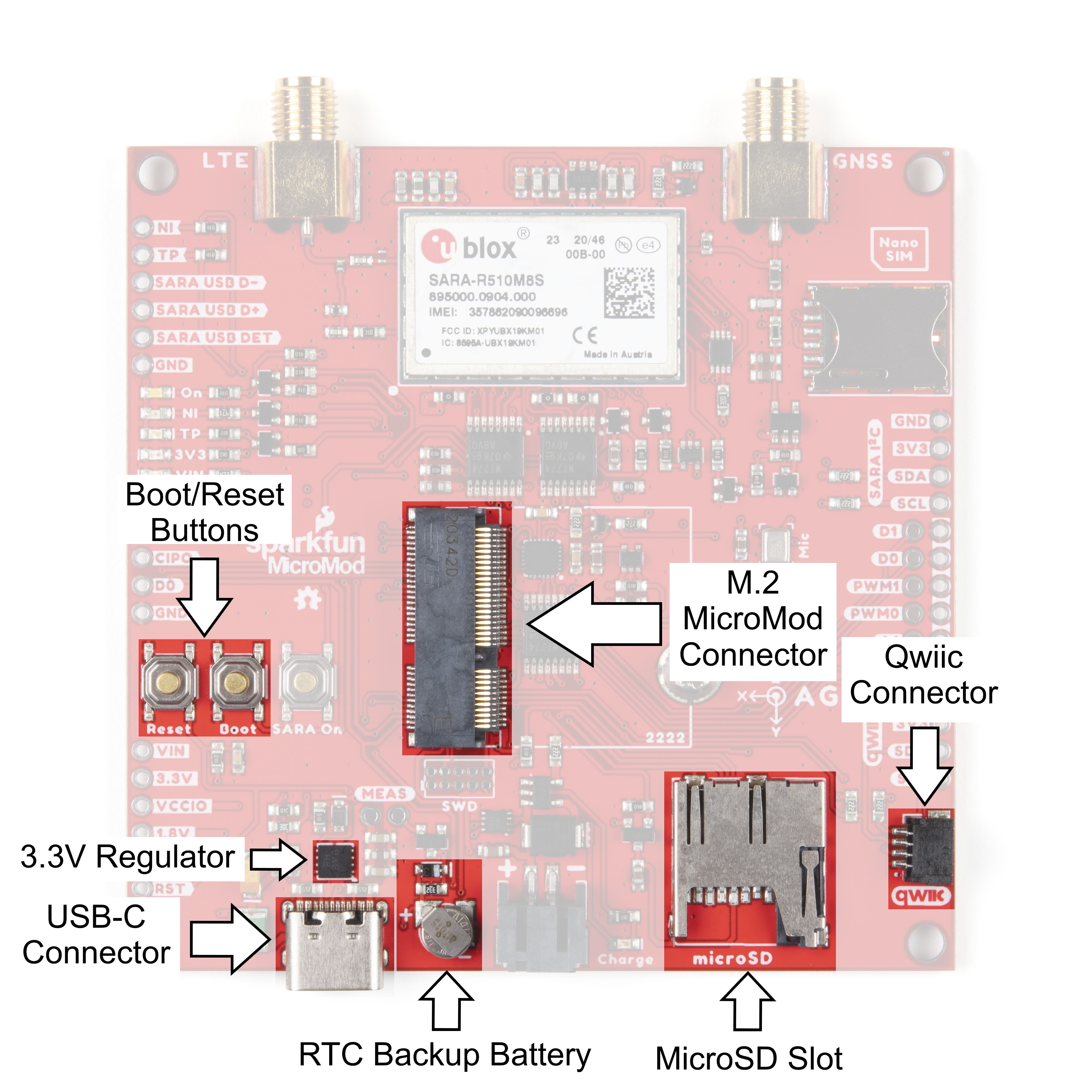
Hardware Overview
The MicroMod Asset Tracker has a lot going on so buckle up. In this section we'll cover the various components
and hardware included on the Asset Tracker.
Common Components
Most SparkFun MicroMod Carriers will have some common components and all MicroMod Carriers will have the
keyed M.2 MicroMod Connector to plug your processor into. The photo and list below outline some of the
components you can expect on most SparkFun MicroMod Carriers.
M.2 MicroMod Connector - This special keyed M.2 connector lets you install your MicroMod Processor of
choice on your Asset Tracker Carrier Board.
USB-C Connector - Connect to your computer to program your Processor and also can provide power to
your MicroMod system.
Serial Communication
Asynchronous serial communication concepts: packets,
signal levels, baud rates, UARTs and more!
Installing an Arduino Library
How do I install a custom Arduino library? It's easy!
This tutorial will go over how to install an Arduino
library using the Arduino Library Manager. For libraries
not linked with the Arduino IDE, we will also go over
manually installing an Arduino library.
Logic Levels
Learn the difference between 3.3V and 5V devices and
logic levels.
Getting Started with MicroMod
Dive into the world of MicroMod - a compact interface
to connect a microcontroller to various peripherals via
the M.2 Connector!

3.3V Regulator - Provides a regulated 3.3V and sources up to 1A.
Qwiic Connector - The standard Qwiic connector so you can add other Qwiic devices to your MicroMod
system.
Boot/Reset Buttons - Push buttons to enter Boot Mode on Processor boards and to Reset your MicroMod
circuit.
microSD Slot - Insert a microSD card for reading and writing data.
RTC Battery - We've included a 3V Lithium Rechargeable Battery as a backup power source for the
Processor Board Real Time Clock (if present).
u-blox SARA-R510M8S
The heart of the Asset Tracker is the SARA-R510M8S module from u-blox. This module does so much, it is difficult
to know where to begin!
Note: The MicroMod Asset Tracker uses the "00B" product version of the SARA-R5 module (specifically the
SARA-R510M8S-00B-00). LTE NB-IoT Radio Access Technology, and the LTE FDD bands: 66, 71, 85 are

not supported by this version. Refer to the SARA-R5 datasheet for more information.
Designed to last an IoT lifetime, this module is 5G-ready with the u-blox UBX-R5 chipset. It has built-in end-to-end
security with hardware-based root of trust inside a discrete secure element. It provides a full security suite with
foundation, design and end-to-end security, as well as access control. The built-in u‑blox M8 GNSS receiver
provides accurate and reliable positioning, always and everywhere. It is optimized for ultra-low power consumption
and critical firmware updates can be delivered and services enabled via uFOTA (Firmware Over The Air). There.
We told you it did a lot!
The SARA-R5 supports many different forms of data communication from full TCP/IP sockets and packet switched
data, through HTTP Get/Put/Post, FTP (the SARA has a built-in file system), Ping, to good old SMS text
messaging! The built-in GNSS receiver provides NMEA format data and our library looks after the parsing for you.
The connection between the SARA-R5 and the MicroMod Processor Board is serial (3.3V UART) but again, with
this module being so clever, it can communicate over two serial interfaces at the same time. Want your LTE data
on one interface and your GNSS data on a separate interface? It can do that too!
Note: Only some of our MicroMod Processors fuly support dual serial interfaces. If this is an important
feature for you please see the "Choosing a Processor Board" section below for more details.
LTE and GNSS connections are via separate, robust SMA connectors. Switchable 3.3V power for an active
antenna is available on the GNSS connector. The Asset Tracker includes a socket for a Nano SIM.
If you need to, you can manually turn the SARA off by pushing and holding the SARA On button. The SARA will
disconnect from the network before going into low power sleep. Press the button briefly to turn the SARA back on
again.
ICM-20948 IMU
The Asset Tracker carries the same ICM-20948 9-Degree Of Freedom Inertial Measurement Unit as OpenLog
Artemis. It can provide fast accelerometer, gyro and magnetometer data and can be configured for “Wake On
Motion” too. We have a WOM example ready to go. It has a built-in temperature sensor too.

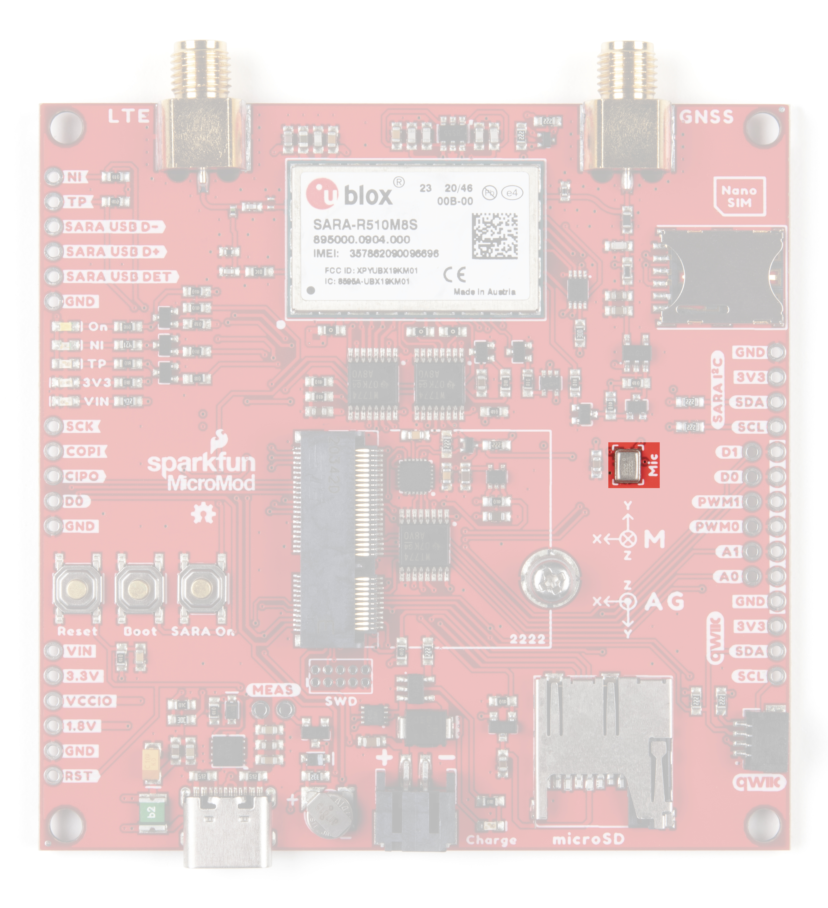
Digital Microphone
Thieves are wily these days. When attempting to steal your asset, one of the first things they will do is cover or
break the antenna (if they can see it). The built-in SPH0641 digital microphone can be used to send an alert as
soon as the Asset Tracker hears the thieves coming!
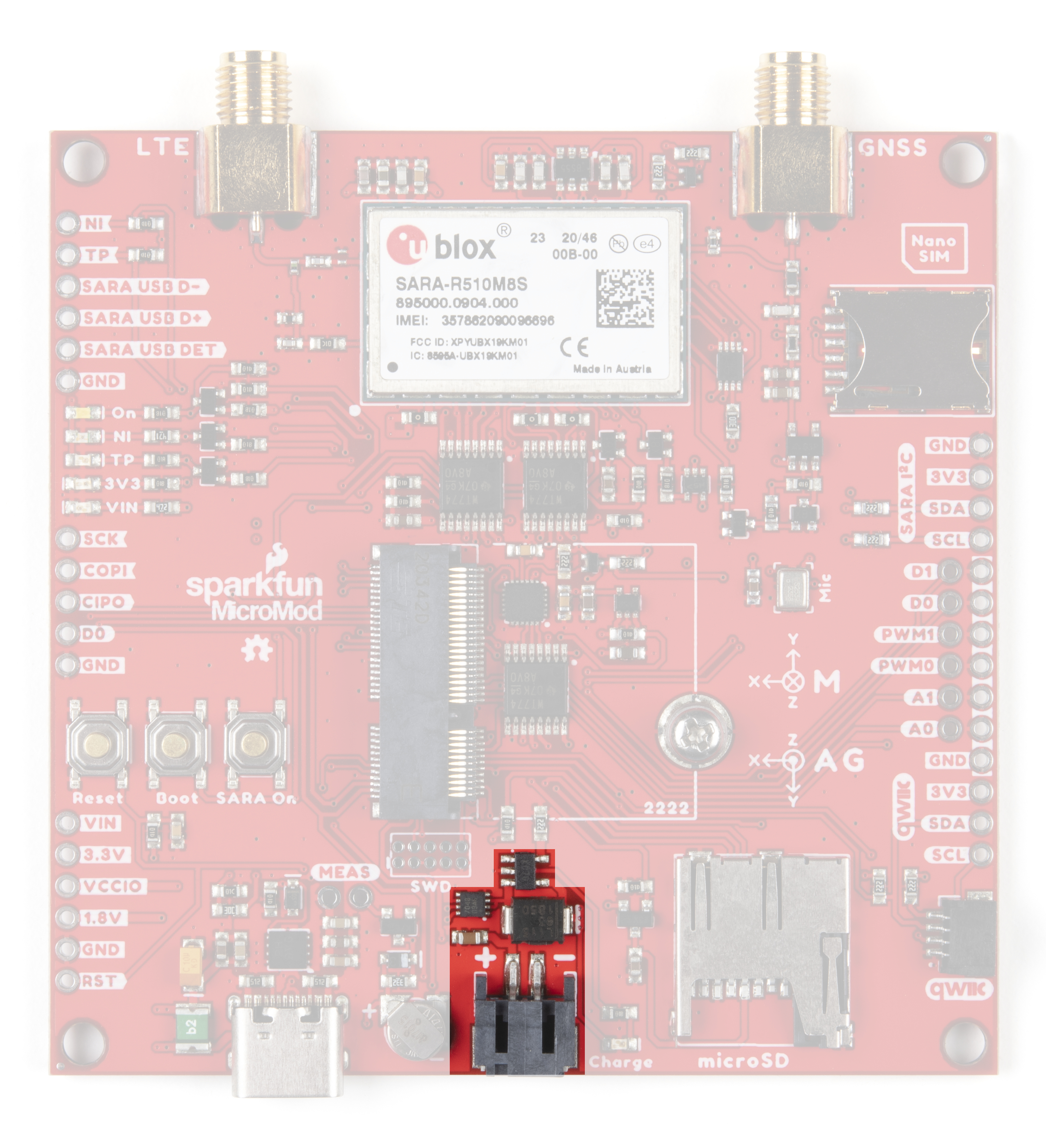
Battery Charging and Monitoring Circuit
Since many applications for the Asset Tracker involve a battery-powered circuit, the board includes both the
MCP73831 LiPo battery charger and the MAX17048 battery fuel gauge. The MCP7381 Single-cell charge
management IC can deliver a charge current up to 500mA. The MAX17048 is a low-power I C fuel gauge to
monitor your battery's remaining charge.
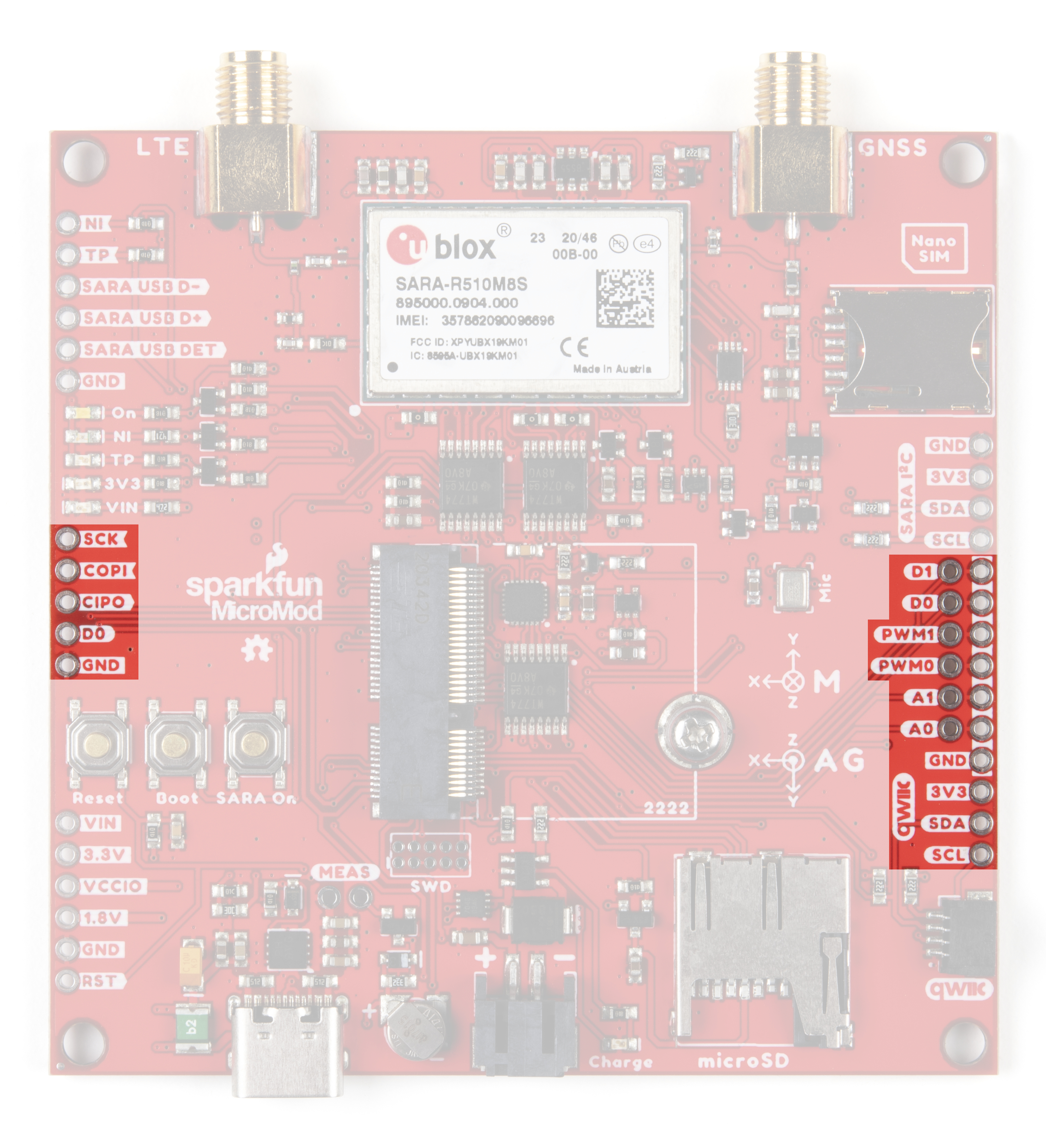
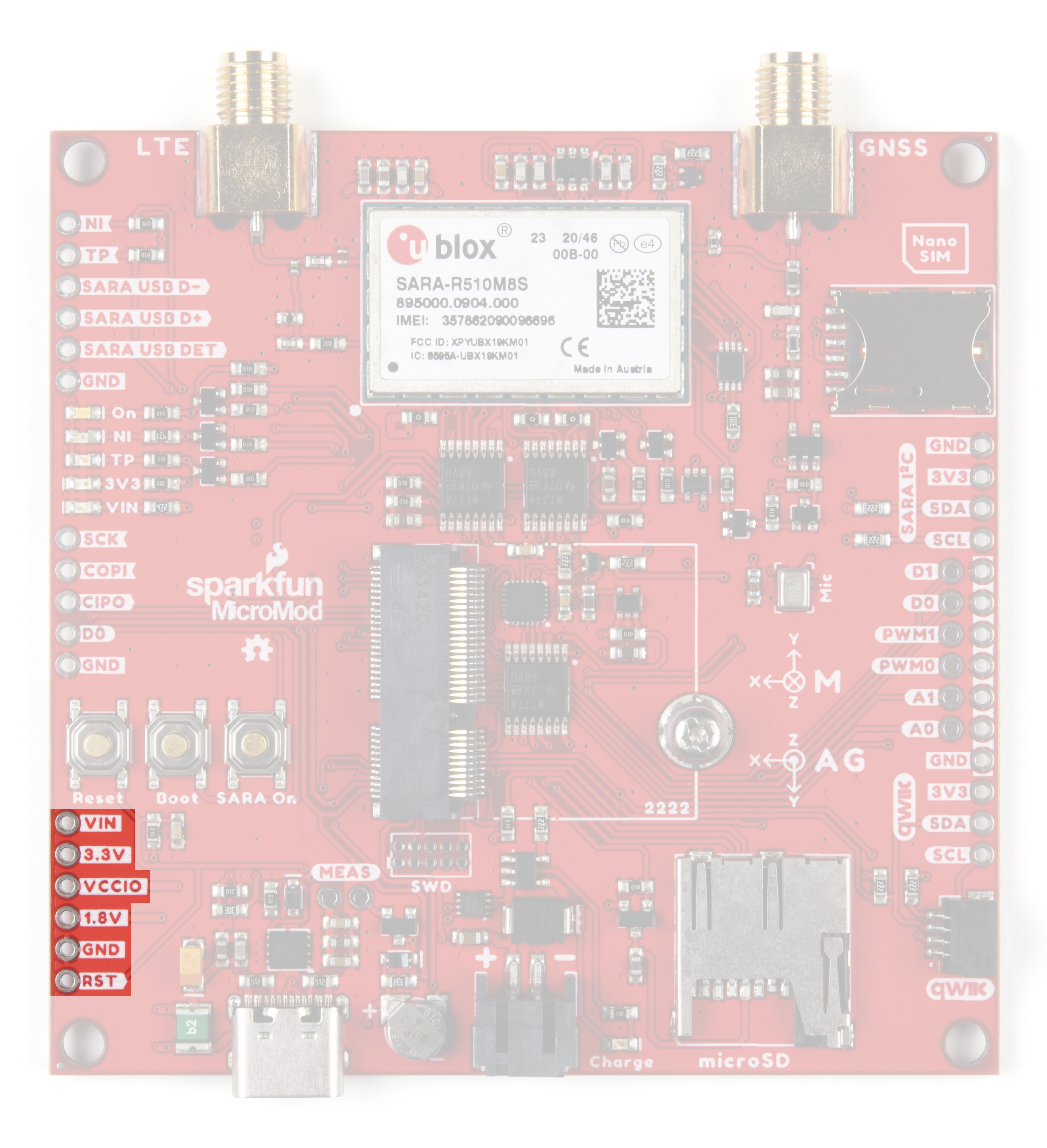
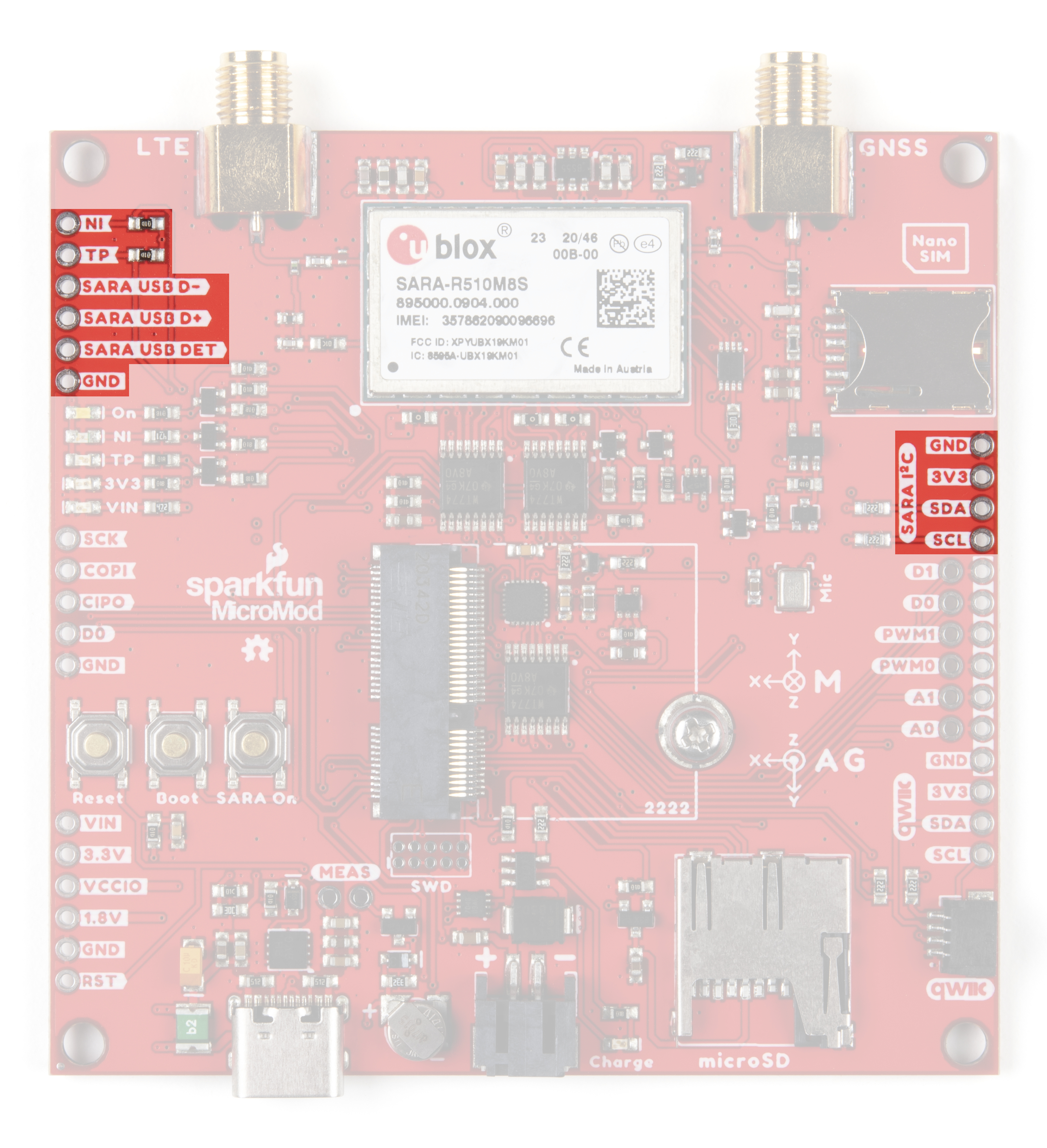
Plated Through-Hole (PTH) Connections
GPIO PTHs
2

We've broken out dedicated PTHs for digital, analog, pulse width modulation (PWM), I C and SPI along the sides
of the Asset Tracker Carrier Board. You may also notice that we've included a ground rail next to the digital, analog
and PWM pins.
Power PTHs
We've also provided PTHs for monitoring and accessing the following power circuits:
VIN - The power rail fed by USB-C and/or the LiPo battery.
3.3V - The regulated 3.3V rail which feeds most of the components on the board. You can measure the 3.3V
current draw using the MEAS pins (see below).
VCCIO - This is the 1.8V rail generated by the SARA-R5. We use it to power the 1.8V to 3.3V level shifters
for the UART and I C connections.
1.8V - This is the 1.8V rail which powers the IMU. You can disable it by pulling the MicroMod G4 digital pin
LOW.
RST - Pull this low to reset the MicroMod Processor and the SARA-R5.
2
2

SARA-R5 PTHs
The following SARA-R5 I/O connections are also broken out to PTH headers:
NI - This is the SARA's Network Indicator signal. It will be low (0V) when the network is available, and high
(3.3V) when the network is not available.
TP - This is the Timing Pulse (1PPS) signal and is connected to SARA GPIO6/TP. It will pulse low and high
when the SARA is receiving a GNSS signal and the timing pulse has been enabled. Please see Example11
for more details.
SARA USB D-/D+/DET - These PTHs provide access to the SARA's diagnostic USB port. This connection
is only used to access the SARA's trace log. You cannot (currently) upgrade the SARA via this interface.
Please consult the SARA R5 Integration Manual for more details.
SARA I C - These 3.3V (level-shifted) PTHs can be used to access the SARA's I C bus. Some models of
the SARA-R5 use I C to communicate with an external GNSS module. As the SARA-R510M8S has GNSS
built-in, it is unclear what you might want to use them for. But, we've been diligent and have broken them out
anyway!
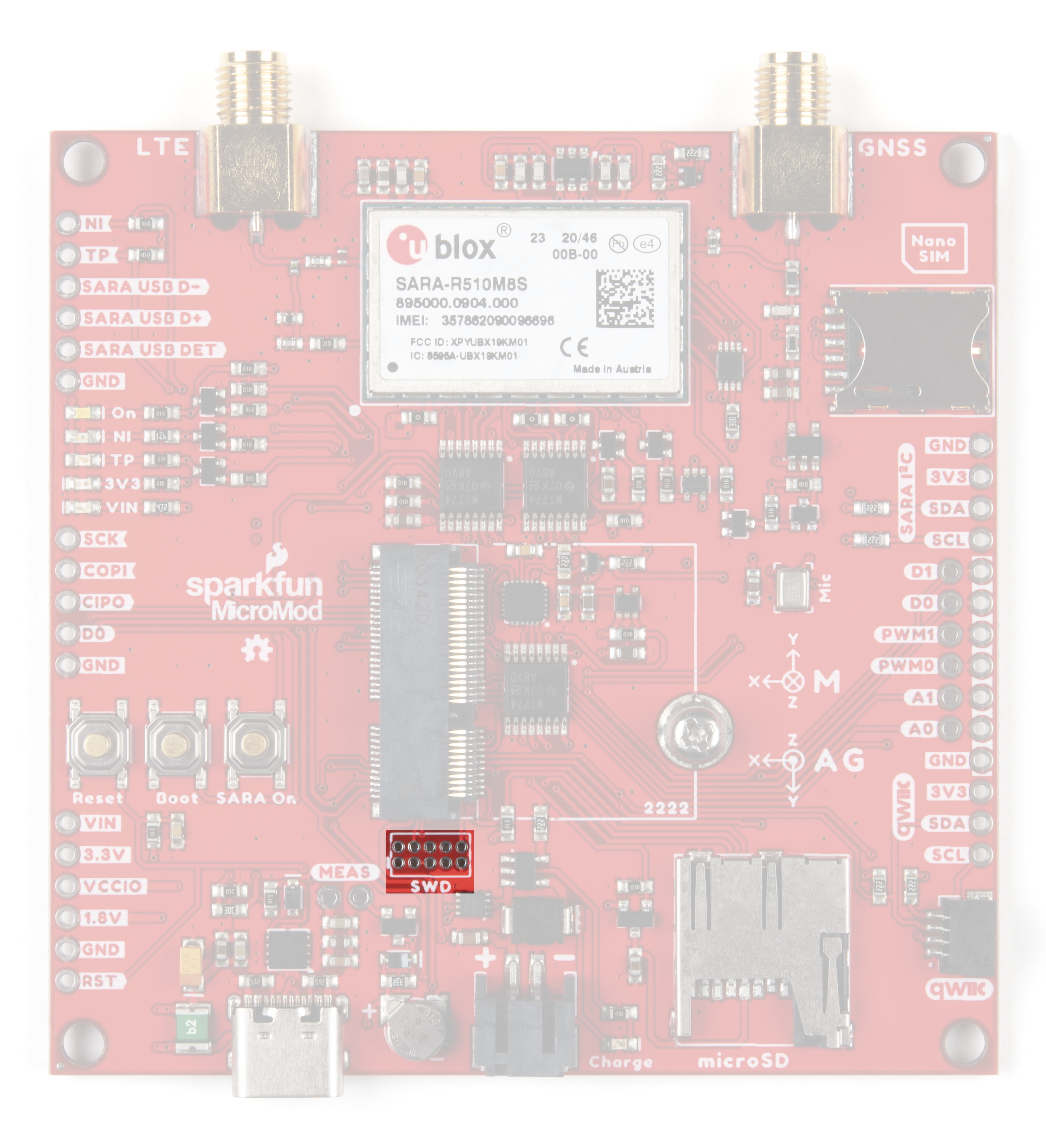
SWD Programming Pins
An unpopulated JTAG footprint is available for more advanced users who need breakpoint level debugging. Note
that this is not populated so you will need a compatible header and compatible JTAG programmer to connect.
22
2

Solder Jumpers
If you have never worked with solder jumpers and PCB traces before or would like a quick refresher, check
out our How to Work with Solder Jumpers and PCB Traces tutorial for detailed instructions and tips.
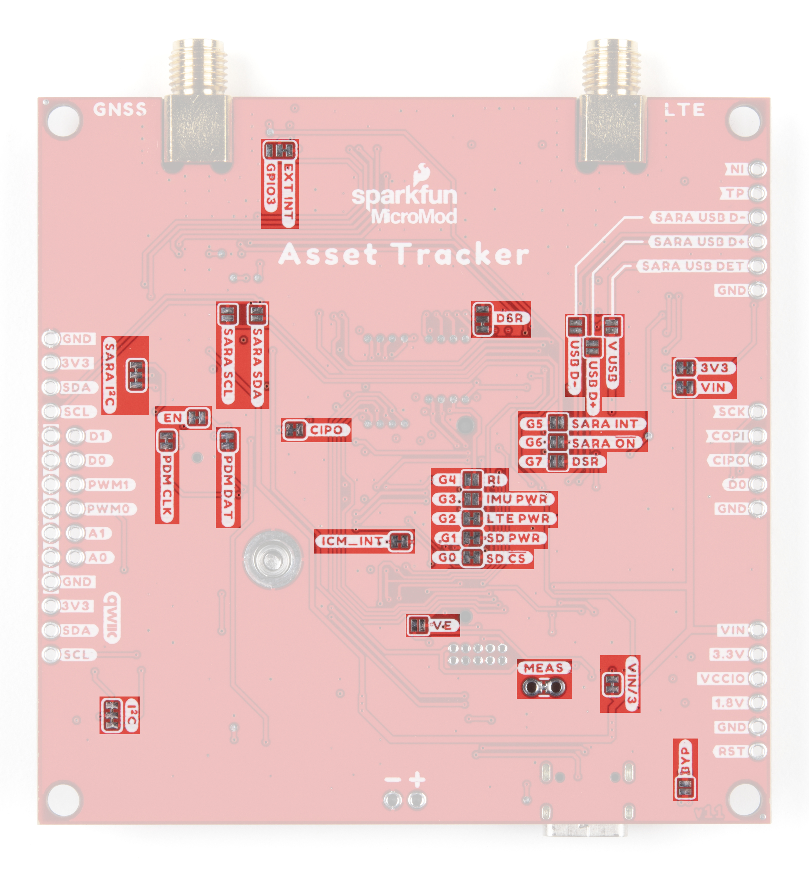
On the rear of the board, you will find a large number of jumpers which you can use to connect and disconnect
several of the connections between the SARA and the MicroMod Processor:
Having trouble seeing the detail in the photo? Click on it for a larger view.
The tables below outline all of the jumpers on the Asset Tracker along with brief descriptions of their functionality.

Jumper
Name/Label
Description Default
State
Notes
G0 / SD CS Ties the µSD Chip Enable to G0 CLOSED
G1 / SD
PWR
Toggles 3.3V to control power the
µSD card.
CLOSED Open to isolate G1. µSD will default to
always on.
G2 /
LTE_PWR
Connects G2 to the SARA-R5 ON
signal via a level-shifting circuit.
CLOSED Allows G2 to function in the exact same
way as the SARA On button. Cut the
jumper to isolate G2 if required.
G3 / IMU
PWR
When closed, G3 can be used to
control power for the IMU via
software. By default, IMU power is
always on.
OPEN On the ESP32 Processor G3 is linked
directly to the processor's TX1 pin. Leave
the G3 jumper OPEN if you are using the
ESP32 Processor or else serial
communication with the SARA will not
work.
G4 / RI When closed, connects G4 to the
SARA-R5's Ring Indicator pin.
OPEN On the ESP32 Processor, G4 is shared
with the processor's RX1 pin. Similarly, G4
is shared with SPI CIPO on the RP2040
Processor. Leave this jumper OPEN if
using either Processor to avoid serial
communication errors with the SARA.
G5 / SARA
INT
When closed, connects G5 with either
the SARA-R5's Interrupt I/O pin or the
SARA's GPIO3 I/O pin depending on
the state of the EXT INT / GPIO3 dual
jumper (covered below).
OPEN On the RP2040 Processor, G5 is shared
with SPI Chip Select line. Closing the
jumper will interfere with the SPI bus on
the RP2040 Processor.
G6 / SARA
ON
When closed, this jumper allows G6
to monitor if the SARA power is on.
OPEN This signal is different to the SARA On
push-button. On the RP2040 Processor,
G6 is shared with the SPI Clock line.
Closing this jumper will interfere with the
SPI bus on the RP2040 Processor.
G7 / DSR When closed, connects G7 to the
SARA's DSR signal.
OPEN On the RP2040 Processor, G7 is shared
with the SPI COPI line. Leave this jumper
open to avoid interfering with the SPI bus
on this processor.
SOLDER JUMPERS (STANDARD)
SOLDER JUMPERS (ADVANCED)

PDM DAT Connects the data signal from on-
board microphone to AUD_LRCLK
(MicroMod Pad 52).
CLOSED On the RP2040 Processor, AUD_LRCLK is
shared with CTS1. Open this jumper to use
the CTS connection on the SARA.
PDM CLK Connects the clock signal from the
on-board microphone to AUD_BCLK
(MicroMod Pad 50).
CLOSED On the RP2040 Processor, AUD_BCLK is
shared with RTS1. Open this jumper to use
the RTS connection on the SARA.
I C A dual jumper that ties SDA & SCL
on the primary I C/Qwiic bus to 3.3V
via a pair of 2.2kΩ resistors.
CLOSED Open both jumpers to disconnect the pull-
ups.
SARA I C A dual jumper that ties the SARA's
SDA and SCL lines to 3.3V via a pair
of 2.2kΩ
CLOSED Open both jumpers to disable the pull-ups.
CIPO Ties SPI CIPO/SDI to 3.3V via a
2.2kΩ resistor.
CLOSED Open to disconnect the pull-up. Opening
this jumper may be advantageous for very
low power applications where Processors
like the Artemis have internal pull-ups
which can be used instead.
EXT INT /
GPIO3
A dual jumper used to select which
signal is connected to MicroMod G5.
SEE
NOTE
By default, this jumper is set so if the G5 /
SARA INT jumper is closed, G5 is
connected to the SARA EXT INT I/O pin.
Switch this jumper to the opposite side to
connect G5 to the SARA GPIO3 pin.
DSR A dual jumper used to control the
direction of DSR from input to output .
SEE
NOTE
By default, this jumper sets DSR as an
input. Switching it sets DSR as an output
so users can use dual-UART
communication modes on the SARA.
MEAS Allows users to measure the current
draw from the 3.3V power rail.
CLOSED Open this jumper and complete the circuit
using a digital multimeter to measure
current draw on the 3.3V power rail.
VIN/3 Completes the VIN/3 voltage divider
circuit.
CLOSED Open the jumper to disable the VIN/3
voltage divider circuit. Disabling this can be
useful in very low power applications to
reduce total current draw.
3V3 (LED) Connects the anode of the 3.3V LED
to 3.3V via a 1kΩ resistor.
CLOSED Open the jumper to disable the 3.3V LED
to reduce total current draw of the
MicroMod circuit.
2
2
2

VIN (LED) Connects the anode of the VIN LED
to VIN (5V if powered by USB, 3.7V
nominal if powered by LiPo battery)
via a 4.7kΩ resistor.
CLOSED Open the jumper to disable the VIN LED to
reduce the total current draw of the
MicroMod circuit.
ICM_INT Connects the ICM IMU Interrupt pin
to the primary I C Interrupt pin
(I2C_INT) on the MicroMod
connector.
CLOSED Open the jumper to isolate the MicroMod
I2C_INT pin from the ICM-20948. On the
RP2040 Processor, I2C_INT is shared with
TX2. You may need to open this jumper to
use the DTR handshake signal.
MicroMod Pinout
Wondering what the pins are that are broken out on the MicroMod Asset Tracker Carrier Board? The tables below
outline the Asset Tracker pinout as well as the general MicroMod pinout. Remember to compare the pins against
your Processor Board to determine which pins are available.
Note: You may not recognize the COPI/CIPO labels for SPI pins. SparkFun is working to move away from
using MISO/MOSI to describe signals between the controller and the peripheral. Check out this page for
more on our reasoning behind this change.
AUDIO UART GPIO/BUS I C SDIO SPI0 Dedicated
M.2 Connector Pin# MicroMod Pin Name Asset Tracker
Connection
Description
1 GND GND Ground plane.
2 3.3V 3.3V Regulated 3.3V via USB-
C.
3 USB_D+ Passthrough USB D+ connection for
Processor Board.
4 3.3V_EN 3.3V Enable Voltage regulator enable
input.
2
MICROMOD ASSET TRACKER PINOUT TABLE
MICROMOD GENERAL PINOUT TABLE
MICROMOD GENERAL PIN DESCRIPTIONS
2

5 USB_D- Passthrough USB D- connection for
Processor Board.
6 RESET RESET Button Connected to RESET
Button. Reset is active
LOW
9 USB_VIN VIN Input voltage from USB.
10 D0 SPI PTH CS/D0 PTH SPI Chip Select for SPI
PTH Header. D0 also
broken out for I/O PTHs
11 BOOT BOOT Button Connected to BOOT
Button. Boot is active
LOW.
12 I2C_SDA I2C_SDA I C data for Fuel Gauge
& Qwiic connector
13 UART_RTS1 SARA RTS_I UART Request to Send
for SARA
14 I2C_SCL I2C_SCL I C clock for Fuel Gauge
& Qwiic connector
15 UART_CTS1 SARA CTS_O UART Clear to Send for
SARA
16 I2C_INT# IMU INT IMU Interrupt pin
17 UART_RX1 SARA TXD_O SARA UART Data Iutput
18 D1 D1 General digital I/O PTH
19 UART_TX1 SARA TXD_I SARA UART Data Output
20 UART_RX2 SARA DCD_O/RXD2_O SARA UART Data Carrier
Detect / AUX UART Data
Output
21 SWDCK SWDCK Serial Wire Debug Clock
22 UART_TX2 SARA DTR_I/TXD2_I SARA UART Data
Terminal Ready / AUX
UART Data Input
23 SWDIO SWDIO Serial Wire Debug I/O
32 PWM0 PWM0 PWM0 PTH
2
2

34 A0 A0 A0 PTH (Input Only)
34 A1 A1 A1 PTH (Input Only)
40 G0/BUS0 SD CS General purpose pin
configured for Chip
Select on µSD.
42 G1/BUS1 microSD_PWR General purpose pin
configured for µSD
Power Enable
44 G2/BUS2 LTE_PWR_ON General purpose pin
configured for turning
SARA on/off
46 G3/BUS3 ICM_PWR General purpose pin
configured for controlling
IMU power
48 G4/BUS4 SARA RI_O/CTS2_O SARA UART Ring
Indicator / AUX UART
Clear to Send
49 BATT_VIN/3 VIN/3 Divided input voltage for
monitoring power supply.
50 AUD_BCLK I2S_SCK/PDM_CLK Microphone PDM clock
signal
51 I2C_SDA1 SARA I2C SDA SARA I C data signal
52 AUD_LRCLK I2S_WS/PDM_DAT Microphone PDM data
signal
53 I2C_SCL1 SARA I2C SCL SARA I C clock signal
55 SPI_CS# ICM_CS Chip select for IMU level
shifting IC
57 SPI_SCK SPI_SCK SPI Clock
59 SPI_COPI SPI_SDO SPI controller
out/peripheral in
61 SPI_CIPO SPI_SDO SPI controller
in/peripheral out
2
2

69 G7/BUS7 SARA DSR_O/RTS2_I SARA UART Data Set
Ready / AUX UART
Request to Send
71 G6/BUS6 SARA_ON General purpose pin
conifgured to monitor
power for SARA
72 RTC_3V RTC_3V 3V output for backup
battery charging.
73 G5/BUS5 SARA_INT General purpose pin
configured for SARA
Interrupt I/O pin
74 3.3V 3.3V 3.3V output from voltage
regulator
Board Dimensions
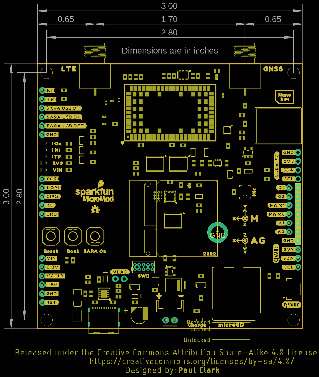
The Asset Tracker Carrier Board measures 3.0 inches by 3.0 inches (76.2mm x 76.2mm) and has four mounting
holes that fit a 4-40 screw.
Having trouble seeing the details in the image? Click on it for a larger view!
Choosing a Processor Board
As you can see from the Jumpers section above, there are some things to consider when choosing a MicroMod
Processor Board to go with your Asset Tracker.

The MicroMod M.2 connector pinout is very comprehensive and some of the processor chips on our MicroMod
Processor Boards just don't have enough I/O pins to let us allocate one to every M.2 pin. So, on those boards we
share the pins. For example, on the ESP32 Processor Board, you will see that the UART TX1 pin is shared with
the G3 I/O pin and the AUD_OUT pin. We do that so that you can use that pin for TX1 or G3 or AUD_OUT. And
for most users and most Carrier Boards, that's perfectly fine. However, since the SARA-R5 has so many pins that
we need to connect to, the sharing of TX1 and G3 causes a small problem. We need TX1 to communicate with the
SARA, and G3 would normally be used to enable power for the ICM-20948 IMU. We get round that by including a
normally-open split pad jumper on G3 and making the IMU power circuit default to on. Simple!
So, you can use any SparkFun MicroMod Processor in the Asset Tracker, but if you need complete access to all of
the pins then here are the restrictions:
ESP32 Processor
TX1 is shared with G3. This means you cannot close the G3 split pad to enable control of the IMU Power. The IMU
power will need to be always on.
RX1 is shared with G4. This means you cannot close the G4 split pad to access the SARA Ring Indicator / Clear
To Send 2 pin.
AUD_LRCLK is shared with G1. G1 controls the micro-SD power and AUD_LRCLK is connected to the digital
microphone. If you want to use the microphone, you will need to open the G1 split pad jumper. The micro-SD
power will default to on.
AUD_BCLK is shared with G2. G2 can be used to turn the SARA-R5 on/off and AUD_BCLK is connected to the
digital microphone. If you want to use the microphone, you will need to open the G2 jumper. You won’t then be
able to have the processor turn the SARA on and off. The SARA always powers on automatically when power is
connected, so no worries there, and the SARA On button is there if you need it.
Artemis Processor
The Artemis Processor does not support the M.2 TX2 and RX2 pins. This means you cannot use the Artemis to
talk to the SARA using any of the dual-UART variants (called variants 2, 3 and 4 in the SARA-R5 System
Integration Manual). This means you cannot, for example, use UART 1 for your LTE traffic and UART 2 for your
GNSS data. That's all. You can do everything over a single UART anyway.
nRF5280 Processor
The nRF52840 Processor Board supports all of the pins used by the Asset Tracker. There are no restrictions for
this Processor Board.
SAMD51 Processor
The SAMD51 Processor Board does not support RTS1 and CTS1 and so you will not be able to perform hardware
handshaking when using the UART. Serial buffers are so large these days that you probably won’t even notice this
restriction, but it is something to be aware of.
RP2040 Processor
AUD_LRCLK is shared with CTS1. This means that if you want to use hardware handshaking for the UART
communication, you won’t be able to use the digital microphone.
Likewise AUD_BCLK is shared with RTS1, again preventing you from using the microphone and hardware
handshaking at the same time.

I2C_INT is shared with TX2. This means that you cannot use the ICM-20948 IMU interrupt and SARA DTR / TXD2
simultaneously. You can open the ICM_INT split pad to isolate the IMU interrupt signal.
G4, G5, G6 and G7 are shared with the SPI connections SPI_SCK, SPI_COPI, SPI_CIPO and SPI_CS. This
should not be an issue for you, but it does mean you cannot close the G4-G7 jumpers to enable access to:
SARA_RI, SARA_INT, SARA is On, and SARA_DSR.
STM32 Processor
The STM32 Processor Board does not support RTS1 and CTS1 and so you will not be able to perform hardware
handshaking when using the UART. Serial buffers are so large these days that you probably won’t even notice this
restriction, but it is something to be aware of.
The STM32 Processor Board does not support the M.2 TX2 and RX2 pins. This means you cannot use the STM32
to talk to the SARA using any of the dual-UART variants (called variants 2, 3 and 4 in the SARA-R5 System
Integration Manual). You cannot, for example, use UART 1 for your LTE traffic and UART 2 for your GNSS data.
G7 is not supported on the STM32 Processor Board. This should not be an issue for you, but it does mean you
cannot access the SARA is On signal.
Hardware Assembly
Now that we are familiar with the hardware on the Asset Tracker Carrier Board, it's time to assemble it with your
chosen MicroMod Processor and get it connected to your computer.
Inserting Your Processor
With the M.2 MicroMod connector, connecting your processor board is a breeze. Simply match up the key on your
processor's beveled edge connector to the key on the M.2 connector. At a 45° angle, insert the processor board to
the M.2 connector. The processor board will stick up at an angle as seen here:
Once the board is in the socket, gently press the Processor down, grab the set screw and tighten it with a Phillip's
head screwdriver:
Table of contents
Other sparkfun Computer Hardware manuals

sparkfun
sparkfun WIG-13660 User manual

sparkfun
sparkfun MicroMod SAMD51 Technical document

sparkfun
sparkfun DEV-14034 Technical document

sparkfun
sparkfun RTK Express Technical document

sparkfun
sparkfun MicroMod Artemis Processor User manual

sparkfun
sparkfun FTDI SmartBasic Technical document

sparkfun
sparkfun H3LIS331DL User manual

sparkfun
sparkfun Gator:soil Technical document

sparkfun
sparkfun NEO-M8P-2 Technical document

sparkfun
sparkfun AST-CAN485 Technical document


