ACPro A Series User manual

AC Pro A-Series 18-24K
Service Manual
Models
AWH18QD-D3DNB8K/I
AWH18QD-D3DNA5K/O
AWH24QE-D3DNB8K/I
AWH24QE-D3DNA5K/O
(Refrigerant R410A)

We reserve the right to correct any clerical errors.
Copyright 2018 AC pro.

Technical Information
1
PART I :INSTALLATION &MAINTENANCE
1. NOTES FOR INSTALLATION AND MAINTENANCE
SAFETY PRECAUTIONS:
IMPORTANT!
Please read the safety precautions carefully before
installation or prior to performing any maintenance.
Please follow instructions below.
• Maintenance or installation MUST be in accordance
with instructions.
• Comply with ALL local and national electrical codes.
• Pay attention to ALL warnings and cautions in this
manual.
• Any maintenance and/or installation shall be
performed by distributors or licensed and qualified
individual.
• Electrical work MUST be performed by licensed
technician according to local regulations and the
instructions given in this manual.
• Use extreme caution when performing electrical
installation tasks – Electric shock can result in
severe injury or death.
WARNINGS!
1. Disconnect power supply prior to ANY work.
2. The air conditioner is a specialized circuit that
requires its own power supply – this is not to be
shared with ANY other electrical appliances.
3. The air conditioner should be installed in a suitable
location and the power supply should be easily
reachable by ALL users.
4. During maintenance and installation, make sure
wiring terminals are securely fastened.
5. Ground wire MUST be firmly connected and NOT
used for other purposes.
6. Use protective accessories as necessary, (IE:
protective boards, cable-cross loop, wire clips, etc.).
7. Live wire, neutral wire, and ground wire MUST
correspond to the live wire, neutral wire, and ground
wire of the air conditioner.
8. Power cord and power connections MUST be free
of obstruction and CANNOT be compressed.
9. Should power cord or power connection become
severed, they MUST be repaired/replaced by
qualified technician.
10. If the power cord or power connection wire is not
long enough, replace with specialized cable from
manufacturer before proceeding with installation or
repair. DO NOT elongate these wires.
11. An air switch MUST be installed if there is no plug
found on the air conditioner. The air switch MUST
be all-pole parting and the contact parting distance
MUST be at 1/8” or greater.
12. All wires and pipes MUST be connected firmly prior
to supplying the unit with power.
13. Eliminate any electric leakage on the unit body.
14. Fuses MUST be replaced with fuse of the same
specification(s). DO NOT replace with copper wire
or conducting wire.
15. If the unit is being installed in a humid climate, a
circuit breaker MUST also be installed.
INSTALLATION SAFETY PRECAUTIONS
1. Select installation location according to
the requirements of this manual. (See the
requirements of installation section in this manual.).
2. Handle unit with care. If unit exceeds 44.09
pounds, use the two-person lift technique to
transport.
3. Use a sufficient fixing bolt when installing both
the indoor and outdoor unit(s). Ensure installation
support is firm.
4. Use safety belt and personal protection equipment
(PPE) while working above a height of 6’.
5. Use equipped components or appointed
components during installation.
6. Make sure to clear the unit of any/all foreign objects
prior to completion of installation.
REFRIGERANT SAFETY PRECAUTIONS
1. Avoid contact of fire and refrigerant as the
combination creates poisonous gas.
2. Use only specified refrigerant. DO NOT mix
refrigerant types. DO NOT allow air to remain in
refrigerant lines as this may lead to pipe rupture or
other hazards.
3. Check entire system for refrigerant leaks prior to
completing installation.

Technical Information 2
IF SAFETY PRECAUTIONS
FOR INSTALLING AND
RELOCATING THE UNIT:
WARNINGS!
1. When installing or relocating the unit, be sure to
keep the refrigerant circuit free from air and other
substances other than the specified refrigerant.
Presence of air or other foreign substance in the
refrigerant lines will cause the system pressure to
rise and could cause the compressor to rupture –
causing injury.
2. When installing or moving the unit, DO NOT charge
with refrigerant other than the specified type listed
on the nameplate of the unit.
This will cause abnormal operation, improper actions
and mechanical malfunction and may result in
serious injury.
3. Refrigerant recovery during relocation or repair:
Ensure unit is running in cooling mode. Fully close
valve at high pressure side (liquid valve). After 30
seconds, fully close valve at low pressure side (gas
valve). Immediately stop the unit and disconnect
power. Total time for refrigerant recovery should not
exceed 1 minute.
If refrigerant recovery takes too much time, air may
be sucked in causing the pressure to rise and the
compressor to rupture which can lead to severe
injury or death.
4. During refrigerant recovery, make sure the liquid and
gas lines are fully closed and power is disconnected
before detaching the connection pipe.
If the compressor starts running while stop valve is
open and connection pipe is not affixed, air will be
sucked in causing pressure to rise and potentially
causing compressor rupture which may lead to
severe injury or death.
5. When installing the unit, make sure the connection
pipe is securely connected before the compressor
starts running.
If the compressor starts running while stop valve is
open and connection pipe is not affixed, air will be
sucked in causing pressure to rise and potentially
causing compressor rupture which may lead to
severe injury or death.
6. DO NOT install the unit in an area exposed to (or
potentially exposed to) corrosive or flammable gas
leaks.
Leaking gas near the unit may cause fire or
explosion leading to property damage, severe injury
or death.
7. DO NOT use extension cords for electrical
connections. If the electrical wire in not long
enough, contact a local service authorized center to
install the proper length wiring.
Poor connections may lead to electrical shock or fire.
8. Use manufacturer specific wires for connections
between indoor and outdoor units. Firmly clamp
wires between indoor and outdoor units. Ensure
terminals receive NO external stress.
Electric wires with insufficient capacity, improper
connection points, and/or improperly secure
terminals may cause electric shock or fire.

Technical Information
3
MAIN TOOLS FOR INSTALLATION AND MAINTENANCE
1. Level meter, measuring
tape
2. Screwdrivers 3. Impact drill, drill head, electric drill
4. Electroprobe 5. Universal meter 6.Torque wrench, open-end wrench, inner
hexagon spanner
7. Electronic leakage detector 8. Vacuum pump 9. Pressure meter
10. Pipe pliers, pipe cutter 11. Pipe expander, pipe bender 12. Soldering appliance, refrigerant container

Technical Information 4
2. INSTALLATION
2.1INSTALLATION DIMENSION DIAGRAM
53
Installation and Maintenance
Service Manual
8. Installation
8.1 Installation Dimension Diagram
unit:inch
Space to the ceiling
Space to the wall
At least 8
At least 72
At least 6
At least 6
Space to the wall
Space to the obstruction
roolfehtotecapS
Space to the obstruction
Drainage pipe
Space to the wall
Space to the obstruction
Space to the obstructi
o
Space to the obstruction
At least 24
At least 12
At least 24
At least 12
At least 78
At least 118
Space to the obstruction
Technical Information
5
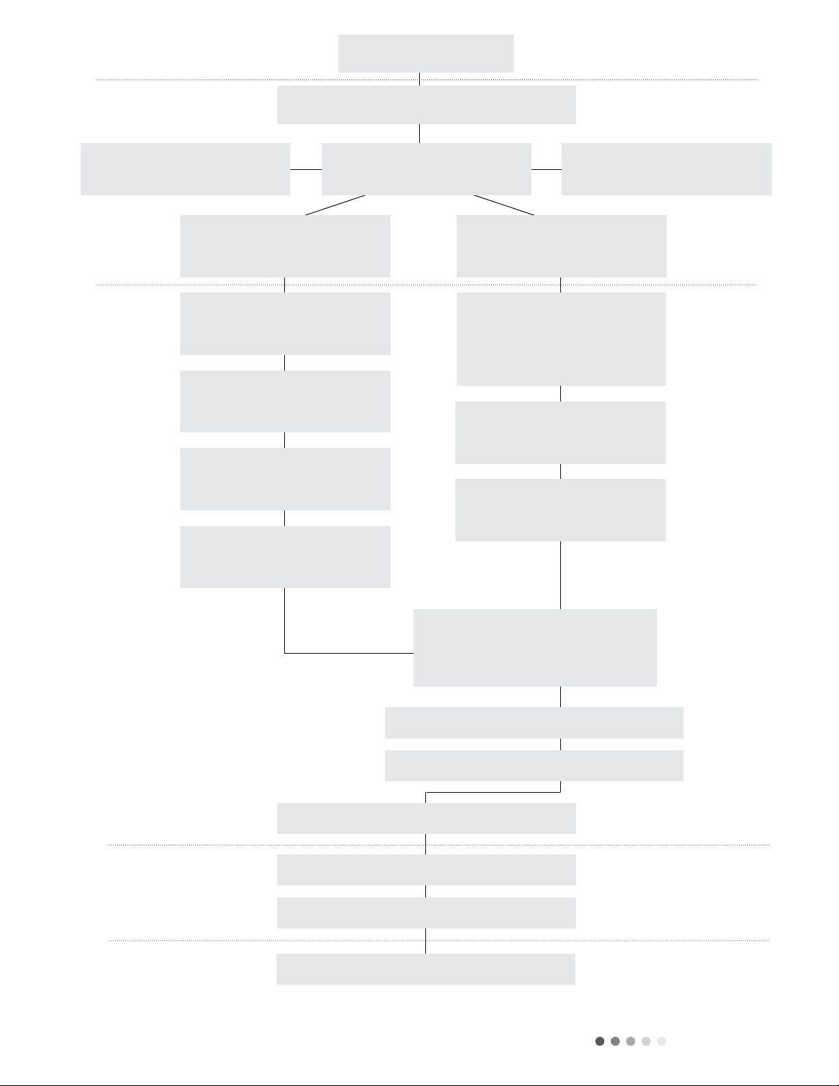
Start installation
Preparation before installation
Read the requirements for
electric connection Select installation location Prepare tools
Select indoor unit
installation location
Select outdoor unit
installation location
Install wall-mounting frame,
drill wall holes
Connect pipes of indoor unit
and drainage pipe
Connect wires of
indoor unit
Bind up pipes and hang
the indoor unit
Install the support of
outdoor unit
(select it according to the
actual situation)
Fix outdoor unit
Make the bound pipes pass
through the wall hole and then
connect outdoor unit
Install drainage joint of
outdoor unit (only for cooling
and heating unit)
Connect pipes of outdoor unit
Connect wires of outdoor unit
Neaten the pipes
Vacuum pumping and leakage detection
Check after installation and test operation
Finish installation
Note: this flow is only for reference; please find the more detailed installation steps in this section.

Technical Information 6
2.2 INSTALLATION PARTS CHECKING
No. Name No. Name
1Indoor Unit 8Sealing Gum
2Outdoor Unit 9Wrapping Tape
3 Connection Pipe 10 Support of Outdoor
Unit
4 Drainage Pipe 11 Fixing screw
5 Wall Mounting
Frame
12 Drainage plug (cooling
and heating unit)
6Power Cord 13 Owner’s Manual,
Remote Controller
7 Wall Pipe
!
Note:
1. Installation MUST be completed by qualified technician.
2. Use manufacturer provide power cord.
2.3 SELECTION OF INSTALLATION
LOCATION
1. Basic Requirement:
Installing the unit in the following places may cause
malfunction. If installation location is unavoidable, consult local
dealer for advice.
• Locations with strong heat sources, vapors, and/or
flammable or explosive gases.
• Locations with high frequency devices such as medical
equipment and welding machines.
• Areas of high humidity.
2. Indoor Unit:
• There should be no obstruction near the air inlet/outlet.
• Select a location where the condensate can be dispersed
easily.
• Location of outdoor unit should be close to connect to
outdoor power supply.
• Location should be out of the reach of children.
• The location should be able to withstand the weight of the
indoor unit without increasing noise and vibration.
• Appliance MUST be installed 72” above the floor.
• The appliance CANNOT be installed in a laundry area.
3. Outdoor Unit:
• Select location so outflow air and noise emitted by outdoor
unit will not affect neighborhood.
• Location should be in well ventilated area and away from
strong wind.
• The foundation should be able to withstand the weight of
the outdoor unit.
• Ensure installation adheres to the installation diagram
dimensions.
• Select installation location which is out of the reach of
children, animals and plant growth. If this is unavoidable,
install protective fencing.
2.4 REQUIREMENTS FOR
ELECTRIC CONNECTION
1. Safety Precaution
• Follow ALL electric safety requirements during
installation.
• Use qualified power supply circuit and air switch –
according to local safety regulations.
• Power supply MUST match the requirement of the air
conditioner. Unstable power supply or incorrect wiring
may result in electric shock, fire hazard, or malfunction.
Install proper power supply cables prior to using air
conditioner.
• Properly connect the live wire, neutral wire and grounding
wire.
• Prior to engaging in any electrical work, disconnect the
power supply.
• DO NOT energize system prior to installation completion.
• Instructions for Y-Type attachment installation:
o If power supply cord is damaged in any way, it MUST
be replace by manufacturer.
• Keep interconnection cable away from copper tube.
Temperature of refrigerant circuit is high.
2. Grounding Requirement:
• Electric shock may result if air conditioner is not grounded
properly.
• Grounding wire in air conditioner is yellow-green and MAY
NOT be used for ANY other purposes.
• Grounding resistance MUST comply with national electric
safety regulations.
• Position appliance so plug is accessible.
• All-pole disconnect switch MUST have contact separation
of at least 1/8” in all poles.
NOTE:
Following table for air switch capability:
Air-conditioner Air switch capacity
18/24K 25A
2.5 INSTALLATION OF INDOOR UNIT
1. Choosing Installation Iocation
• Recommend location to client for approval.
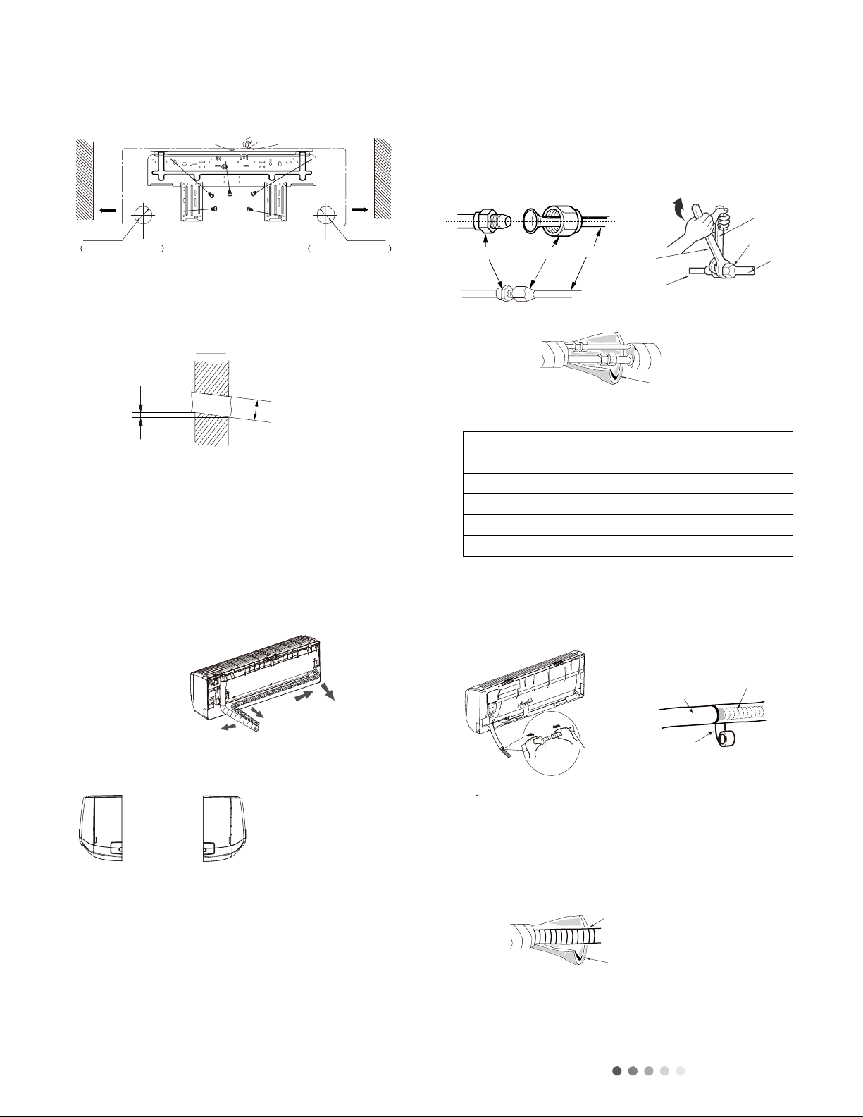
2. Install Wall-mounting Frame
• Position wall-mounting frame on wall, adjust horizontal
position with level, and mark screw holes on wall.
• Drill screw fixing holes with drill motor. Install plastic
expansion screw set.
• Fix wall-mounting frame to wall with tapping screws
(STA.2X25TA) and check that frame is securely fastened.
• If plastic expansion piece is loose, drill a second hole that
lines up with the frame.
• Choose position of piping hole according to the direction
of the outlet pipe. The position of the piping hole should
be just slightly lower than the wall-mounted frame.
(Shown in figure #1).
Technical Information
7
• Choose position of piping hole according to the direction of
the outlet pipe. The position of the piping hole should be
just slightly lower than the wall-mounted frame. (Shown in
figure #1).
• Open pipe hole with diameter of ɸ2 1/6” on selected outlet
pipe position. For smooth drainage, pitch the pipe hole on
wall slightly downward to the outdoor side with a gradient of
5-10O – (Shown in Figure #2).
!
Note:
• Attend to dust prevention by taking safety measure while
drilling.
• Plastic expansion screw set not included.
3. Outlet Pipe
• Pipe can be led out in the direction of right, rear right, left or
rear left – (Shown in Figure #3 below).
• When selecting leading out pipe (from left or right), cut out
corresponding hole on bottom (Shown in Figures 4 below).
4. Indoor Unit Pipe Connect
• Aim pipe to the corresponding bellmouth (Shown in Figure
#5 below).
• Pre-tighten union nut by hand.
• Use following torque table as reference below. Use double
wrench technique on union nut and pipe joint. Tighten the
union nut with torque wrench (Shown in Figure #6).
• Use insulation tape to wrap indoor pipe and joint of
connection pipe (Shown in Figure #7 below).
Refer to the following table for wrench moment of force:
Hex nut diameter(inch) Tightening Torque (ft:lb)
Φ1/4 11.10~14.75
Φ3/8 22.12~29.50
Φ1/2 33.19~40.56
Φ5/8 44.24~47.94
Φ3/4 51.32~55.31
5. Install Drain Hose
• Connect drain hose to outlet pipe of indoor unit. (Shown in
Figure #8 below).
• Bind the joint with tape (Shown in Figure #9 below).
!
Note:
• Prevent condensation by adding insulation to indoor
drain hose. (Shown in Figure #10 below).
• Plastic expansion screw set not included.
56 Installation and Maintenance
Service Manual
Outlet
pipe
Drain hose
Drain hose
Tape
Outlet pipe
Insulating pip
e
Torque wrenc
h
Open-end
wrench
Indoor pipe
Pipe
Union nut
Union nutPipe joint Pipe
Refer to the following table for wrench moment of force:
Left
Rear left
Right
Rear right
Cut off
the hole
Left Right
Drain hose
Insulating pip
e
5-10
°
Φ2 3/16 or
(Φ2 3/4)inch
Indoor Outdoor
(1) Pay attention to dust prevention and take relevant safety
measures when opening the hole.
(2) The plastic expansion particles are not provided and should
be bought locally.
(1) Add insulating pipe in the indoor drain hose in order to
prevent condensation.
(2) The plastic expansion particles are not provided.
(As show in Fig.10)
Fig.1
Fig.2
Fig.5 Fig.6
Fig.7
Fig.8 Fig.9
Fig.10
Fig.3
Fig.4
in the holes.
(3) Fix the wall-mounting frame on the wall with tapping screws
(ST4.2X25TA) and then check if the frame is rmly installed by
pulling the frame. If the plastic expansion particle is loose,
please drill another xing hole nearby.
3. Install Wall-mounting Frame
(1) Choose the position of piping hole according to the direction
of outlet pipe. The position of piping hole should be a little
lower than the wall-mounted frame.(As show in Fig.1)
5. Connect the Pipe of Indoor Unit
(1) Aim the pipe joint at the corresponding bellmouth.(As show
in Fig.5)
(2) Pretightening the union nut with hand.
(3) Adjust the torque force by referring to the following sheet.
Place the open-end wrench on the pipe joint and place the
torque wrench on the union nut. Tighten the union nut with
torque wrench.(As show in Fig.6)
(4) Wrap the indoor pipe and joint of connection pipe with
insulating pipe, and then wrap it with tape.(As show in Fig.7)
6. Install Drain Hose
(1) Connect the drain hose to the outlet pipe of indoor unit.(As
show in Fig.8)
(2) Bind the joint with tape.(As show in Fig.9)
4. Outlet Pipe
(1) The pipe can be led out in the direction of right, rear right,
left or rear left.(As show in Fig.3)
(2) When selecting leading out the pipe from left or right, please
cut off the corresponding hole on the bottom case.(As show in
Fig.4)
(2) Open a piping hole with the diameter of Φ2 3/16(Φ2 3/4)
inch on the selected outlet pipe position.In order to drain
smoothly, slant the piping hole on the wall slightly downward to
the outdoor side with the gradient of 5-10°.(As show in Fig.2)
Note:
Note:
Hex nut diameter(inch) Tightening torque(ft·Ibf)
Φ1/4 11.10~14.75
Φ3/8 22.12~29.50
Φ1/2 33.19~40.56
Φ5/8 44.24~47.94
Φ3/4 51.32~55.31
Left
Wall
Φ2 3/16(2 3/4) Φ2 3/16(2 3/4)
Right
Mark in the middle of it Level meter
Rear piping hole
Wall
Space
to the
wall
above
6inch
Space
to the
wall
above
6inch
Rear piping hole
Technical Information 8
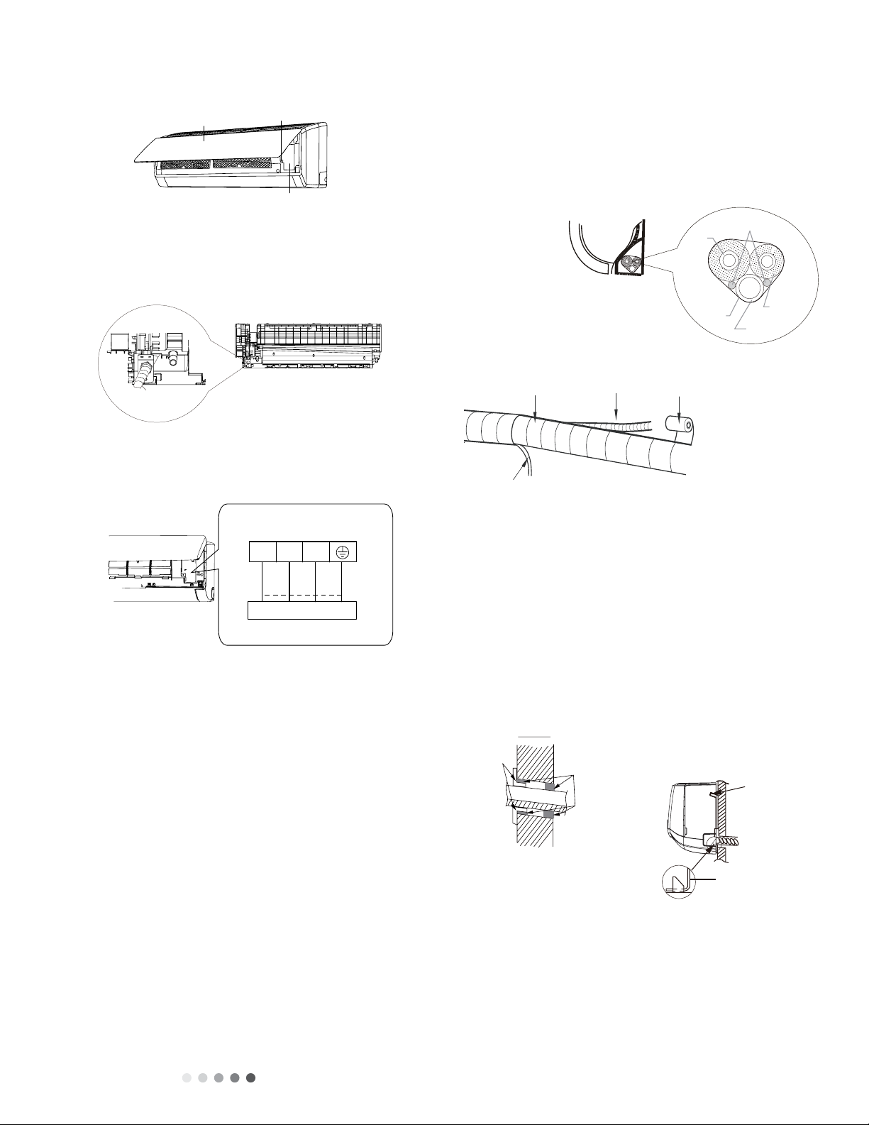
6. Indoor Unit Wire Connection
• Open panel. Remove screw on wiring panel and detach
cover (Shown in Figure #11 below).
• Affix the wire crossing board on the connection wire sleeve
to the bottom of the case. Position the connection wire
sleeve through the wire crossing hole at the back of the
indoor unit. Pull through front (Shown in Figure #12
below).
• Remove wire clip. Attached power connection wire to the
wiring terminal by color. Tighten screw(s) and attach power
connection wire with wire clip (Shown in Figure #13 below).
Note: The wiring connect is for reference only, please refer to
the actual one.
• Wiring board is for reference only.
• Replace wire cover back and tighten screw.
• Close panel.
Note:
• All wires for both indoor and outdoor units MUST be
connected by a professional.
• If the length of the power supply connection cable is
insufficient, contact the supplier for a new one.
• Units that contain plugs MUST have plugs in convenient/
reachable location.
• Units without plugs MUST have an air switch installed in
the line. The air switch MUST be all-pole parting and the
contact distance MUST be more than 1/8”.
7. Bind Up Pipe
• Bind the connection pipe, power cord and drain hose with
band. Shown in Figure #14 below).
• Reserve a length of drain hose and power cord for installation
during binding. When binding to a specific degree, separate
the indoor power and separate the drain hose (Shown in Figure
#15 below).
• Bind all cordage and hoses evenly.
• The liquid and gas pipes should be bound separately at the
end.
Note:
• The power cord and control wire cannot be crossed.
• The drain hose should be bound to the bottom.
8. Hang the Indoor Unit
• Insert bound pipes in to wall pipe and pass them through hole
in wall.
• Hang indoor unit on the wall mounting frame.
• Stuff gap between pipes and wall hole with sealing gum.
• Affix the wall pipe (Shown in Figure #16 below).
• Ensure indoor unit is close to the wall and installed securely
(shown in Figure #17 below).
Note:
• DO NOT excessively bend the drain hose. Doing so may
cause a blockage.
57
Installation and Maintenance
Service Manual
connection wire sleeve
(4) Put wiring cover back and then tighten the screw.
(5) Close the panel.
Indoor unit Gas
pipe
Indoor and
outdoor power cord
Liquid
pipe
Drain hose
Band
Drain hose Band
Connection pipe
Indoor power cord
(1) All wires of indoor unit and outdoor unit should be
connected by a professional.
(2) If the length of power connection wire is insufcient, please
contact the supplier for a new one. Avoid extending the wire by
yourself.
(3) For the air conditioner with plug, the plug should be
reachable after nishing installation.
(4) For the air conditioner without plug, an air switch must be
installed in the line. The air switch should be all-pole parting
and the contact parting distance should be more than 3mm.
(1) The power cord and control wire cant be crossed or
winding.
(2) The drain hose should be bound at the bottom.
Do not bend the drain hose too excessively in order to prevent
blocking.
7. Connect Wire of Indoor Unit
(1) Open the panel, remove the screw on the wiring cover and
then take down the cover.(As show in Fig.11)
8. Bind up Pipe
(1) Bind up the connection pipe, power cord and drain hose
with the band.(As show in Fig.14)
(2) Reserve a certain length of drain hose and power cord
for installation when binding them. When binding to a certain
degree, separate the indoor power and then separate the drain
hose.(As show in Fig.15)
(3) Bind them evenly.
(4) The liquid pipe and gas pipe should be bound separately at
the end.
9. Hang the Indoor Unit
(1) Put the bound pipes in the wall pipe and then make them
pass through the wall hole.
(2) Hang the indoor unit on the wall-mounting frame.
(3) Stuff the gap between pipes and wall hole with sealing gum.
(4) Fix the wall pipe.(As show in Fig.16)
(5) Check if the indoor unit is installed rmly and closed to the
wall.(As show in Fig.17)
(2) Fix the wire crossing board on connection wire sleeve at
the bottom case; let the connection wire sleeve go through the
wire crossing hole at the back of indoor unit, and then pull it out
from the front.(As show in Fig.12)
(3) Remove the wire clip; connect the power connection wire
to the wiring terminal; tighten the screw and then x the power
connection wire with wire clip.(As show in Fig.13)
Note:
Note:
Note:
Indoor Outdoor
Wall pipe Sealing gum
Upper hook
Lower hook of
wall-mounting frame
Fig.11
Fig.12
Fig.13
Fig.14
Fig.15
Fig.16
Fig.17
Wiring cover
Screw
Panel
Note: the wiring board is for reference only,please refer to the
actual one.
Outdoor unit connection
3
2
N(1)
green
green)
red
black
(yellow-
(brown)
white
(blue)
Note: the wiring board is for reference only,please refer to the actual one.
57
Installation and Maintenance
Service Manual
connection wire sleeve
(4) Put wiring cover back and then tighten the screw.
(5) Close the panel.
Indoor unit Gas
pipe
Indoor and
outdoor power cord
Liquid
pipe
Drain hose
Band
Drain hose
Band
Connection pipe
Indoor power cord
(1) All wires of indoor unit and outdoor unit should be
connected by a professional.
(2) If the length of power connection wire is insufcient, please
contact the supplier for a new one. Avoid extending the wire by
yourself.
(3) For the air conditioner with plug, the plug should be
reachable after nishing installation.
(4) For the air conditioner without plug, an air switch must be
installed in the line. The air switch should be all-pole parting
and the contact parting distance should be more than 3mm.
(1) The power cord and control wire cant be crossed or
winding.
(2) The drain hose should be bound at the bottom.
Do not bend the drain hose too excessively in order to prevent
blocking.
7. Connect Wire of Indoor Unit
(1) Open the panel, remove the screw on the wiring cover and
then take down the cover.(As show in Fig.11)
8. Bind up Pipe
(1) Bind up the connection pipe, power cord and drain hose
with the band.(As show in Fig.14)
(2) Reserve a certain length of drain hose and power cord
for installation when binding them. When binding to a certain
degree, separate the indoor power and then separate the drain
hose.(As show in Fig.15)
(3) Bind them evenly.
(4) The liquid pipe and gas pipe should be bound separately at
the end.
9. Hang the Indoor Unit
(1) Put the bound pipes in the wall pipe and then make them
pass through the wall hole.
(2) Hang the indoor unit on the wall-mounting frame.
(3) Stuff the gap between pipes and wall hole with sealing gum.
(4) Fix the wall pipe.(As show in Fig.16)
(5) Check if the indoor unit is installed rmly and closed to the
wall.(As show in Fig.17)
(2) Fix the wire crossing board on connection wire sleeve at
the bottom case; let the connection wire sleeve go through the
wire crossing hole at the back of indoor unit, and then pull it out
from the front.(As show in Fig.12)
(3) Remove the wire clip; connect the power connection wire
to the wiring terminal; tighten the screw and then x the power
connection wire with wire clip.(As show in Fig.13)
Note:
Note:
Note:
Indoor Outdoor
Wall pipe Sealing gum
Upper hook
Lower hook of
wall-mounting frame
Fig.11
Fig.12
Fig.13
Fig.14
Fig.15
Fig.16
Fig.17
Wiring cover
Screw
Panel
Note: the wiring board is for reference only,please refer to the
actual one.
Outdoor unit connection
3
2
N(1)
green
green)
red
black
(yellow-
(brown)
white
(blue)
Note: the wiring board is for reference only,please refer to the actual one.
57
Installation and Maintenance
Service Manual
connection wire sleeve
(4) Put wiring cover back and then tighten the screw.
(5) Close the panel.
Indoor unit Gas
pipe
Indoor and
outdoor power cord
Liquid
pipe
Drain hose
Band
Drain hose Band
Connection pipe
Indoor power cord
(1) All wires of indoor unit and outdoor unit should be
connected by a professional.
(2) If the length of power connection wire is insufcient, please
contact the supplier for a new one. Avoid extending the wire by
yourself.
(3) For the air conditioner with plug, the plug should be
reachable after nishing installation.
(4) For the air conditioner without plug, an air switch must be
installed in the line. The air switch should be all-pole parting
and the contact parting distance should be more than 3mm.
(1) The power cord and control wire cant be crossed or
winding.
(2) The drain hose should be bound at the bottom.
Do not bend the drain hose too excessively in order to prevent
blocking.
7. Connect Wire of Indoor Unit
(1) Open the panel, remove the screw on the wiring cover and
then take down the cover.(As show in Fig.11)
8. Bind up Pipe
(1) Bind up the connection pipe, power cord and drain hose
with the band.(As show in Fig.14)
(2) Reserve a certain length of drain hose and power cord
for installation when binding them. When binding to a certain
degree, separate the indoor power and then separate the drain
hose.(As show in Fig.15)
(3) Bind them evenly.
(4) The liquid pipe and gas pipe should be bound separately at
the end.
9. Hang the Indoor Unit
(1) Put the bound pipes in the wall pipe and then make them
pass through the wall hole.
(2) Hang the indoor unit on the wall-mounting frame.
(3) Stuff the gap between pipes and wall hole with sealing gum.
(4) Fix the wall pipe.(As show in Fig.16)
(5) Check if the indoor unit is installed rmly and closed to the
wall.(As show in Fig.17)
(2) Fix the wire crossing board on connection wire sleeve at
the bottom case; let the connection wire sleeve go through the
wire crossing hole at the back of indoor unit, and then pull it out
from the front.(As show in Fig.12)
(3) Remove the wire clip; connect the power connection wire
to the wiring terminal; tighten the screw and then x the power
connection wire with wire clip.(As show in Fig.13)
Note:
Note:
Note:
Indoor Outdoor
Wall pipe Sealing gum
Upper hook
Lower hook of
wall-mounting frame
Fig.11
Fig.12
Fig.13
Fig.14
Fig.15
Fig.16
Fig.17
Wiring cover
Screw
Panel
Note: the wiring board is for reference only,please refer to the
actual one.
Outdoor unit connection
3
2
N(1)
green
green)
red
black
(yellow-
(brown)
white
(blue)
Note: the wiring board is for reference only,please refer to the actual one.

Technical Information
9
2.6 INSTALLATION OF OUTDOOR UNIT
1. Support of Outdoor Unit
• Select according to actual installation situation. Select
installation location according to the structure.
• Affix outdoor unit support with expansion screws.
!
Note:
• Use personal protection equipment while performing
installation.
• Prep the outdoor unit to support up to four times the weight of
the unit.
• Outdoor unit should be installed at least 1 1/16” above the floor
in order to install drain joint. (Shown in Figure #18 below).
• Six expansion screws should be used for units with cooling
capacities of 2,300W – 5,000W.
• Eight expansion screws should be used for units with cooling
capacities of 6,000W – 8,000W.
• Ten expansion screws should be used for units with cooling
capacities of 10,000W – 16,000W.
2. Install Drain Joint
• Connect outdoor drain joint to the hole in the chassis.
• Connect drain hose to drain vent (Shown in Figure #19
above).
3. Outdoor Unit
• Place outdoor unit on support.
• Affix the foot holes of the outdoor unit with appropriate
bolts. (Shown in Figure #20 below).
4. Connect Indoor and Outdoor Pipes
• Remove screw on right cable cross plate sub-assy and valve
cover of outdoor unit then remove the cable cross plate sub-
assy and valve cover (Shown in Figure #21 above).
• Remove the screw cap of valve and aim the pipe joint at the
bellmouth of pipe (Shown in Figure #22 below).
• Pretighten the union nut by hand.
• Tighten the union nut with torque wrench. Refer to table.
Refer to the following table for wrench moment of force:
Hex nut diameter(inch) Tightening Torque (ft:lb)
Φ1/4 11.10~14.75
Φ3/8 22.12~29.50
Φ1/2 33.19~40.56
Φ5/8 44.24~47.94
Φ3/4 51.32~55.31
5. Connect Outdoor Electric Wire
• Insert power connection wire and power wire through wire-
passing hole.
• Remove wire clip and connect the power connect wire and
the power wire to wiring terminal. Affix with screws (Shown
in Figure #23 below).
• Affix the power connection wire and power wire with wire
clip.
• Install the cable cross plate sub-assy.
!
Note:
• After tightening the screw, pull the power cord slightly to check
if it is firm.
• NEVER cut the power connection wire to prolong or shorten
the overall length of the wire.
• Connecting wire and connection pipe CANNOT touch each
other.
• Top cover of outdoor unit and electric box assembly should
be secured by screws. WARNING: Water and dust can cause
short circuit and fire if top cover is not secured.
6. Neaten the Pipes
• Pipes should be placed along the wall, reasonably bent and
hidden if possible. Minimum semi-diameter of bending pipe
is 4 inches.
• If outdoor unit is higher than wall hole, set U-shaped curve
in pipe before inserting into wall hole in order to prevent rain
from getting in the room (Shown in Figure #24 below).
!
Note:
• The through-wall height of drain hose should not be higher
than the outlet pipe hole of the indoor unit (Shown in Figure
#25 above).
• Angle drain hose slightly downward. Drain hose CANNOT be
curved or bent (Shown in Figure #26 above).
• In order to drain smoothly, the water outlet CANNOT be placed
in water (Shown in Figure #27 below).
58 Installation and Maintenance
Service Manual
(1) Take sufficient protective measures when installing the
outdoor unit.
(2) Make sure the support can withstand at least four times the
unit weight.
(3) The outdoor unit should be installed at least 1 3/16 inch
above the oor in order to install drain joint.(As show in Fig.18)
(4) For the unit with cooling capacity of 2300W~5000W, 6
expansion screws are needed; for the unit with cooling capacity
of 6000W~8000W, 8 expansion screws are needed; for the
unit with cooling capacity of 10000W~16000W, 10 expansion
screws are needed.
(1) After tightening the screw, pull the power cord slightly to
check if it is rm.
(2) Never cut the power connection wire to prolong or shorten
the distance.
(1) The through-wall height of drain hose shouldnt be higher
than the outlet pipe hole of indoor unit.(As show in Fig.25)
(2) Slant the drain hose slightly downwards. The drain hose
cant be curved, raised and uctuant, etc.(As show in Fig.26)
Note:
Note:
Note:
The drain hos
can't raise
upwards
gas pipe
Liquid pipe
Liquid
valve
gas valve
Union nut
Pipe joint
Foot holes
Foot holes
8.6 Installation of Outdoor Unit
1. Fix the Support of Outdoor Unit(Select it according to
the actual installation situation)
(1) Select installation location according to the house structure.
(2) Fix the support of outdoor unit on the selected location with
expansion screws.
5. Connect Outdoor Electric Wire
(1) Let the connection wire sleeve go through the two holes of
bafe; tighten the connection joint of sleeve and bafe; remove
the wire clip; connect the power connection wire and power
cord to the wiring terminal according to the color; x them with
screws.(As show in Fig.23)
6. Neaten the Pipes
(1) The pipes should be placed along the wall, bent reasonably
and hidden possibly. Min. semidiameter of bending the pipe is 3
15/16inch.
(2) If the outdoor unit is higher than the wall hole, you must set
a U-shaped curve in the pipe before pipe goes into the room,
in order to prevent rain from getting into the room.(As show in
Fig.24)
(2) Fix the power connection wire and power cord with wire clip.
(3) Fix the stopper on handle with screw.
2. Install Drain Joint(only for cooling and heating unit)
(1) Connect the outdoor drain joint into the hole on the chassis.
(2) Connect the drain hose into the drain vent.
(As show in Fig.19)
3. Fix Outdoor Unit
(1) Place the outdoor unit on the support.
(2) Fix the foot holes of outdoor unit with bolts.
(As show in Fig.20)
4. Connect Indoor and Outdoor Pipes
(1) Remove the screw on the right handle and valve cover of
outdoor unit and then remove the handle and valve cover.(As
show in Fig.21)
(2) Remove the screw cap of valve and aim the pipe joint at the
bellmouth of pipe.(As show in Fig.22)
(3) Pretightening the union nut with hand.
(4) Tighten the union nut with torque wrench .
Hex nut diameter(inch) Tightening torque(ft·Ibf)
Φ1/4 11.10~14.75
Φ3/8 22.12~29.50
Φ1/2 33.19~40.56
Φ5/8 44.24~47.94
Φ3/4 51.32~55.31
Refer to the following table for wrench moment of force:
Fig.18 Fig.19
Fig.20 Fig.21
Fig.22
Fig.23
Fig.24
Fig.25
U-shaped curve
Wall
Drain hose
A
t least 1 3/16 inch above the floo
r
Chassis
Outdoor drain join
t
Drain hose
Drain ven
t
Handle
Valve cover
Note: the wiring board is for reference only,please refer to the
actual one.
Handle
Indoor unit connection
POWER
N(1) 23L1
L1
L2 G
L2
(blue)
white (blue)
whitered
black
(brown)
(brown)
black
(yellow-
green
green) (yellow-
green
green)
58 Installation and Maintenance
Service Manual
(1) Take sufficient protective measures when installing the
outdoor unit.
(2) Make sure the support can withstand at least four times the
unit weight.
(3) The outdoor unit should be installed at least 1 3/16 inch
above the oor in order to install drain joint.(As show in Fig.18)
(4) For the unit with cooling capacity of 2300W~5000W, 6
expansion screws are needed; for the unit with cooling capacity
of 6000W~8000W, 8 expansion screws are needed; for the
unit with cooling capacity of 10000W~16000W, 10 expansion
screws are needed.
(1) After tightening the screw, pull the power cord slightly to
check if it is rm.
(2) Never cut the power connection wire to prolong or shorten
the distance.
(1) The through-wall height of drain hose shouldnt be higher
than the outlet pipe hole of indoor unit.(As show in Fig.25)
(2) Slant the drain hose slightly downwards. The drain hose
cant be curved, raised and uctuant, etc.(As show in Fig.26)
Note:
Note:
Note:
The drain hos
can't raise
upwards
gas pipe
Liquid pipe
Liquid
valve
gas valve
Union nut
Pipe joint
Foot holes
Foot holes
8.6 Installation of Outdoor Unit
1. Fix the Support of Outdoor Unit(Select it according to
the actual installation situation)
(1) Select installation location according to the house structure.
(2) Fix the support of outdoor unit on the selected location with
expansion screws.
5. Connect Outdoor Electric Wire
(1) Let the connection wire sleeve go through the two holes of
bafe; tighten the connection joint of sleeve and bafe; remove
the wire clip; connect the power connection wire and power
cord to the wiring terminal according to the color; x them with
screws.(As show in Fig.23)
6. Neaten the Pipes
(1) The pipes should be placed along the wall, bent reasonably
and hidden possibly. Min. semidiameter of bending the pipe is 3
15/16inch.
(2) If the outdoor unit is higher than the wall hole, you must set
a U-shaped curve in the pipe before pipe goes into the room,
in order to prevent rain from getting into the room.(As show in
Fig.24)
(2) Fix the power connection wire and power cord with wire clip.
(3) Fix the stopper on handle with screw.
2. Install Drain Joint(only for cooling and heating unit)
(1) Connect the outdoor drain joint into the hole on the chassis.
(2) Connect the drain hose into the drain vent.
(As show in Fig.19)
3. Fix Outdoor Unit
(1) Place the outdoor unit on the support.
(2) Fix the foot holes of outdoor unit with bolts.
(As show in Fig.20)
4. Connect Indoor and Outdoor Pipes
(1) Remove the screw on the right handle and valve cover of
outdoor unit and then remove the handle and valve cover.(As
show in Fig.21)
(2) Remove the screw cap of valve and aim the pipe joint at the
bellmouth of pipe.(As show in Fig.22)
(3) Pretightening the union nut with hand.
(4) Tighten the union nut with torque wrench .
Hex nut diameter(inch) Tightening torque(ft·Ibf)
Φ1/4 11.10~14.75
Φ3/8 22.12~29.50
Φ1/2 33.19~40.56
Φ5/8 44.24~47.94
Φ3/4 51.32~55.31
Refer to the following table for wrench moment of force:
Fig.18 Fig.19
Fig.20 Fig.21
Fig.22
Fig.23
Fig.24
Fig.25
U-shaped curve
Wall
Drain hose
A
t least 1 3/16 inch above the floo
r
Chassis
Outdoor drain joint
Drain hose
Drain ven
t
Handle
Valve cover
Note: the wiring board is for reference only,please refer to the
actual one.
Handle
Indoor unit connection
POWER
N(1) 23L1
L1
L2 G
L2
(blue)
white (blue)
whitered
black
(brown)
(brown)
black
(yellow-
green
green) (yellow-
green
green)
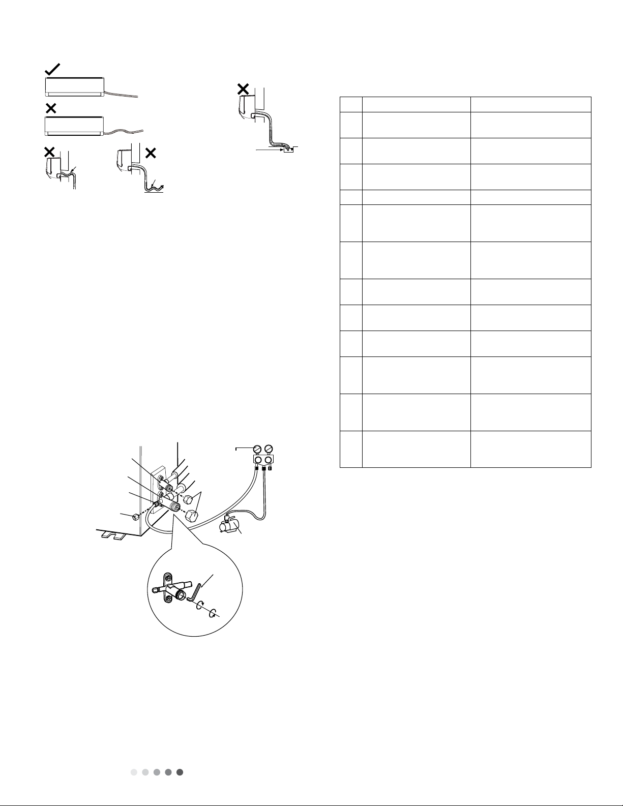
Technical Information 10
c. The water outlet cant be placed in water in order to drain
smoothly.(As show in Fig.27)
2.7 VACUU
M PUMPING AND LEAK
DETECTION
1. Use Vacuum Pump
• Remove valve caps from liquid valve and gas valve and form
the nut of refrigerant charging vent.
• Connect charging hose of piezometer to the refrigerant
charging vent of the gas valve. Then connect the other
charging hose to the vacuum pump.
• Open piezometer completely and operate unit for 10-15
minutes in order to check pressure level of piezometer. Should
remain at -0.1MPa.
• Close vacuum pump and keep closed for 1-2 minutes to verify
pressure of piezometer remains at -0.1MPa. If the pressure
decreases, there MAY be leakage.
• Remove piezometer, completely open both the valve core of
the liquid valve and gas valve with an inner hexagon spanner.
• Tighten screw caps of valves and refrigerant charging vent
(Shown in Figure #28 below).
2. Leakage Detection
• Check for leaks using leak detector.
• Use soapy water if leak detector is unavailable. Apply soapy
water to the area in question. Leave soap & water solution on
for 3 minutes. Watch for air bubbles coming from solution to
detect leak.
59
Installation and Maintenance
Service Manual
(3) The water outlet cant be placed in water in order to drain
smoothly.(As show in Fig.27)
Liquid valve
Gas valve
Refrigerant charging
vent
Nut of refrigerant
Charging vent
Vacuum pump
Piezometer
Valve cap
Lo Hi
Inner hexagon
spanner
Open
Close
The drain hose can't be fluctuant
The drain hose
can't be fluctuant The water
outlet can't be
fluctuant
The water outlet
can't be placed
in water
1. Use Vacuum Pump
(1) Remove the valve caps on the liquid valve and gas valve
and the nut of refrigerant charging vent.
(2) Connect the charging hose of piezometer to the refrigerant
charging vent of gas valve and then connect the other charging
hose to the vacuum pump.
(3) Open the piezometer completely and operate for 10-15min
to check if the pressure of piezometer remains in -14.5ISP.
(4) Close the vacuum pump and maintain this status for 1-2min
to check if the pressure of piezometer remains in -14.5ISP. If
the pressure decreases, there may be leakage.
(5) Remove the piezometer, open the valve core of liquid valve
and gas valve completely with inner hexagon spanner.
(6) Tighten the screw caps of valves and refrigerant charging
vent.(As show in Fig.28)
1. Check after Installation
Check according to the following requirement after finishing
installation.
2. Test Operation
(1) Preparation of test operation
● The client approves the air conditioner installation.
● Specify the important notes for air conditioner to the client.
(2) Method of test operation
● Put through the power, press ON/OFF button on the remote
controller to start operation.
● Press MODE button to select AUTO, COOL, DRY, FAN and
HEAT to check whether the operation is normal or not.
● If the ambient temperature is lower than 16℃, the air
conditioner cant start cooling.
2. Leakage Detection
(1) With leakage detector:
Check if there is leakage with leakage detector.
(2) With soap water:
If leakage detector is not available, please use soap water for
leakage detection. Apply soap water at the suspected position
and keep the soap water for more than 3min. If there are air
bubbles coming out of this position, theres a leakage.
8.7 Vacuum Pumping and Leak Detection
8.8 Check after Installation and Test
Operation
Fig.26
Fig.27
Fig.28
NO. Items to be checked Possible malfunction
1Has the unit been
installed rmly?
The unit may drop, shake or
emit noise.
2Have you done the
refrigerant leakage test?
It may cause insufcient cooling
(heating) capacity.
3Is heat insulation of
pipeline sufcient?
It may cause condensation and
water dripping.
4Is water drained well? It may cause condensation and
water dripping.
5
Is the voltage of power
supply according to the
voltage marked on the
nameplate?
It may cause malfunction or
damage the parts.
6Is electric wiring and
pipeline installed
correctly?
It may cause malfunction or
damage the parts.
7Is the unit grounded
securely? It may cause electric leakage.
8Does the power cord
follow the specication?
It may cause malfunction or
damage the parts.
9Is there any obstruction
in air inlet and air outlet?
It may cause insufcient cooling
(heating) capacity.
10
The dust and
sundries caused
during installation are
removed?
It may cause malfunction or
damaging the parts.
11 The gas valve and liquid
valve of connection pipe
are open completely?
It may cause insufcient cooling
(heating) capacity.
12 Is the inlet and outlet
of piping hole been
covered?
It may cause insufcient cooling
(heating) capacity or waster
eletricity.
2.8 CHECK AFTER INSTALLATION
AND TEST OPERATION
1. Check after Installation
Use chart below
No. Check Following Possible Malfunction
1 Was unit installed firmly/
securely?
Unit may shake or emit
rattling noise.
2 Was refrigerant leakage
test performed?
This may cause insufficient
cooling heating) capacity.
3 Is heat insulation of
pipeline sufficient?
May cause condensation
and water leakage.
4Does water drain well? May cause leakage.
5Does voltage of power
supply match voltage
listed on nameplate?
Malfunction and damage to
the unit may result.
6Was electric wiring
and pipeline installed
correctly?
Malfunction and damage to
the unit may result.
7 Was the unit properly
grounded?
May experience electric
leakage.
8Does the power cord
meet specification?
Malfunction and damage to
the unit may result.
9Are there obstructions in
the air inlet/outlet?
This may cause insufficient
cooling heating) capacity.
10 Was unit free of dust and
packing material prior to
installation?
Malfunction and damage to
the unit may result.
11 Are both the gas valve
and liquid valve open
completely?
This may cause insufficient
cooling heating) capacity.
12 Have both the inlet and
outlet piping hole been
covered?
This may cause insufficient
cooling heating) capacity.
May waste electricity.
2. Test Operation
• Prep test operation
o Client approves air conditioner installation.
o Specify the important notes of the air conditioner to the
client.
• Method of test
o Turn on power. Press ON/OFF button on the remote
controller to start operation.
o Press MODE button to select AUTO, COOL, DRY, FAN
and HEAT to check if the operation(s) is functioning.
o If the ambient temperature is lower than 60.8OºF – the
air conditioner cannot begin the cooling cycle.
Technical Information
11
2.9 WIRED CONTROLLER (NOT INCLUDED)
Equipped with wired controller, please refer to the following introductions.
1. Displaying Part
60 Installation and Maintenance
Service Manual
8.9 Wired Controller
If the product you bought is equipped with wired controller, please refer to the following introductions of wired controller.
1.Displaying Part
Fig1.1.1 Outline of wired controller
Fig.1.1.2 LCD display
1.1 LCD Display of Wired Controller
1.2 Instruction to LCD Display
No. Symbols Description
1Swing function
2Air exchange function (this function is yet unavailable for this unit)
3Sleep function (Only sleep 1)
4Each kind of running mode of indoor unit (auto mode)
5Cooling mode
6Dry mode
7Fan mode
8Heating mode
9Defrosting function for the outdoor unit
10 Gate-control function (this function is yet unavailable for this unit)
1.1 LCD Display of Wired Controller
No. Symbols Description
1Swing function
2Air exchange function
3 Sleep function (Only sleep 1)
4 Each kind of running mode of indoor unit (auto mode)
5 Cooling mode
6 Dry mode
7 Fan Mode
8 Heating mode
9Defrosting function for the outdoor unit
10 Gate-control function
60 Installation and Maintenance
Service Manual
8.9 Wired Controller
If the product you bought is equipped with wired controller, please refer to the following introductions of wired controller.
1.Displaying Part
Fig1.1.1 Outline of wired controller
Fig.1.1.2 LCD display
1.1 LCD Display of Wired Controller
1.2 Instruction to LCD Display
No. Symbols Description
1Swing function
2Air exchange function (this function is yet unavailable for this unit)
3Sleep function (Only sleep 1)
4Each kind of running mode of indoor unit (auto mode)
5Cooling mode
6Dry mode
7Fan mode
8Heating mode
9Defrosting function for the outdoor unit
10 Gate-control function (this function is yet unavailable for this unit)

Technical Information 12
No. Symbols Description
11 Lock function
12 SHEILD Shield functions (Button operation, temperature setting, On/Off operation,Mode setting are disabled by the
remote monitoring system.)
13 TURBO Turbo function state
14 MEMORY Memory function (The indoor unit resumes the original setting after power failure and power recovery)
15 It blinks while on
16 SAVE Energy-saving function
17 Ambient/setting temperature value
18 E-HEATER Electric auxiliary heating function
19 BLOW Blow function
20 Time value
21 QUIET Quiet function (two types: quiet and auto quiet)
2 Buttons
2.1 Layout of Buttons
No. Name Description
1 Enter/Cancel Function selection and cancellation.
2Running temperature setting of the indoor unit, range:16~30°C
6Timer setting, range:0.5-24 hr.
3Fan Setting of the high/middle/low/auto fan speed.
4 Mode Setting of the Cooling/Heating/Fan/Dry/Auto mode of the indoor unit.
6 Function Switchover among the functions of Turbo/Save/E-heater/Blow etc.
7 Timer Timer setting.
8On/Off Turn on/off the indoor unit.
4+2 +Mode
Press for 5s under to enter/cancel the Memory function(If memory is set, indoor unit power failure and
power recovery will resume in the original setting state. If not, the indoor unit is defaulted to off after power
recovery. Memory off is default before delivery.).
3+6 Fan+By pressing them at the same time while off, will be displayed on the wired controller for the cooling only
unit, while will be displayed on the wired controller for the cooling and heating unit.
2+6 +Upon startup, press them at the same time for 5s to enter the lock state. Repress them for 5s to quit.
61
Installation and Maintenance
Service Manual
2 Buttons
2.1 Layout of Buttons
2.2 Functions of Buttons
11 Lock function
12 SHIELD Shield functions (Button operation, temperature setting, On/Off operation,Mode setting are
disabled by the remote monitoring system.)
13 TURBO Turbo function state
14 MEMORY Memory function (The indoor unit resumes the original setting state after power failure and
then power recovery)
15 It blinks under on state of the unit without operation of any button
16 SAVE Energy-saving function
17 Ambient/setting temperature value
18 E-HEATER Electric auxiliary heating function(this function is yet unavailable for this unit)
19 BLOW Blow function
20 Timing value
21 QUIET Quiet function (two types: quiet and auto quiet)(this function is yet unavailable for this unit).
No. Name Function
1Enter/Cancel Function selection and cancellation.
2▲①Running temperature setting of the indoor unit, range:16~30°C.
②Timer setting, range:0.5-24 hr.
6▼
3Fan Setting of the high/middle/low/auto fan speed.
4Mode Setting of the Cooling/Heating/Fan/Dry/Auto mode of the indoor unit.
6Function Switchover among the functions of Turbo/Save/E-heater/Blow etc.
7Timer Timer setting.
8On/Off Turn on/off the indoor unit.
4+2 ▲+Mode
Press them for 5s under off state of the unit to enter/cancel the Memory function(If memory
is set, indoor unit after power failure and then power recovery will resume the original
setting state. If not, the indoor unit is defaulted to be off after power recovery. Memory off is
default before delivery.).
3+6 Fan+▼
By pressing them at the same time under off state of the unit, will be displayed on the
wired controller for the cooling only unit, while will be displayed on the wired controller
for the cooling and heating unit.
2+6 ▲+▼
Upon startup of the unit without malfunction or under off state of the unit,press them at the
same time for 5s to enter the lock state, in which case,any other buttons wont respond the
press. Repress them for 5s to quit this state.
60 Installation and Maintenance
Service Manual
8.9 Wired Controller
If the product you bought is equipped with wired controller, please refer to the following introductions of wired controller.
1.Displaying Part
Fig1.1.1 Outline of wired controller
Fig.1.1.2 LCD display
1.1 LCD Display of Wired Controller
1.2 Instruction to LCD Display
No. Symbols Description
1Swing function
2Air exchange function (this function is yet unavailable for this unit)
3Sleep function (Only sleep 1)
4Each kind of running mode of indoor unit (auto mode)
5Cooling mode
6Dry mode
7Fan mode
8Heating mode
9Defrosting function for the outdoor unit
10 Gate-control function (this function is yet unavailable for this unit)
61
Installation and Maintenance
Service Manual
2 Buttons
2.1 Layout of Buttons
2.2 Functions of Buttons
11 Lock function
12 SHIELD Shield functions (Button operation, temperature setting, On/Off operation,Mode setting are
disabled by the remote monitoring system.)
13 TURBO Turbo function state
14 MEMORY Memory function (The indoor unit resumes the original setting state after power failure and
then power recovery)
15 It blinks under on state of the unit without operation of any button
16 SAVE Energy-saving function
17 Ambient/setting temperature value
18 E-HEATER Electric auxiliary heating function(this function is yet unavailable for this unit)
19 BLOW Blow function
20 Timing value
21 QUIET Quiet function (two types: quiet and auto quiet)(this function is yet unavailable for this unit).
No. Name Function
1Enter/Cancel Function selection and cancellation.
2▲①Running temperature setting of the indoor unit, range:16~30°C.
②Timer setting, range:0.5-24 hr.
6▼
3Fan Setting of the high/middle/low/auto fan speed.
4Mode Setting of the Cooling/Heating/Fan/Dry/Auto mode of the indoor unit.
6Function Switchover among the functions of Turbo/Save/E-heater/Blow etc.
7Timer Timer setting.
8On/Off Turn on/off the indoor unit.
4+2 ▲+Mode
Press them for 5s under off state of the unit to enter/cancel the Memory function(If memory
is set, indoor unit after power failure and then power recovery will resume the original
setting state. If not, the indoor unit is defaulted to be off after power recovery. Memory off is
default before delivery.).
3+6 Fan+▼
By pressing them at the same time under off state of the unit, will be displayed on the
wired controller for the cooling only unit, while will be displayed on the wired controller
for the cooling and heating unit.
2+6 ▲+▼
Upon startup of the unit without malfunction or under off state of the unit,press them at the
same time for 5s to enter the lock state, in which case,any other buttons wont respond the
press. Repress them for 5s to quit this state.

Technical Information
13
3 Operation Instructions
3.1 On/Off
Press On/Off to turn unit on or off.
Note: The state shown in Fig.3.1.1 indicates “Off”. The state shown in Fig.3.1.2 indicates “On”.
3.2 Mode Setting
While ON, press Mode to switch the operation modes in the following sequence: Auto–Cooling–Dry–Fan–Heating.
3.3 Temperature Setting
Press or to increase/decrease the preset temperature. Pressing either of them continuously, will increase the temperature by 1°C / 1°F
every 0.5s,as shown in Fig.3.3.1.
In Cooling, Dry, Fan or Heating mode, the temperature setting range is 16~30°C(61~86°F).
In Auto mode, the setting temperature is not adjustable.
3.4 Fan Setting
While ON, press Fan and then fan speed and the indoor unit fan mode change circularly as shown in Fig.3.4.1.
3.5 Timer Setting
While ON, PressTimer button to set timer off. While OFF, press Timer button to set timer ON/OFF.
Timer on setting:
While OFF, pressing timer button will display LCD, press or button to adjust timer on and then pressTimer to confirm.

Technical Information 14
Press Timer to cancel
this setting
Press Enter/Cancel to
confirm this setting
Timer off setting:
IfTimer button is pressed, while on, LCD will display xx. Press or button to adjust timer on and press Timer to confirm.
Cancel timer:
After timer is set, press timer button to display LCD and confirm,
Turn on the unit,without
Timer activated
Press Timer repeatedly
to get to the setting
status
Press /to adjust
the time
Press Timer to cancel
this setting
Press Enter/Cancel to
confirm this setting
Fig.3.5.1 Timer OFF Setting
Figure 3.5.2 TimerON setting while unit is OFF
Turn on the unit, without
Timer activated
Press Timer repeatedly
to get to the setting
status
Press /to adjust
the time

Technical Information
15
Timer range: 0.5-24hr. Press or to increase/decrease set time by 0.5hr. If either of them is pressed continuously, the set time will
increase/ decrease by 0.5hr every 0.5 seconds.
3.6 Swing Setting
Press the SWING button to adjust the fan blowing angle as seen below.
• SWING ON: Press function to activate swinging of louvers. Press ENTER/CANCEL when the icon begins to blink to confirm
swing operation is desired.
• SWING OFF: Press function to deactivate swinging of louvers. Press ENTER/CANCEL when the icon appears cancel swing
operation.
Fig.3.6.1 Swing Setting
Notes:
SLEEP, TURBO and FAN settings are the same as the SWING setting
3.7 Sleep Setting
Under COOL, HEAT or DRY Mode, press this button to start the SLEEP function. Press ENTER/CANCEL to confirm setting.
• In COOL or DRY modes, the system will increase temperature by 1-2ºF each hour after SLEEP mode is enabled.
• In HEAT mode, the system will decrease temperature by 1-2ºF each hour after SLEEP mode is enabled.
Turn off the unit, without
Sleep function activated
Press Function repeatedly
until go to the Swing
setting status
Press Enter/Cancel
to activated the Turbo
function
Press Enter/Cancel to
cancel this setting
Press Function repeatedly
unitll go to the Swing
function again

Technical Information 16
Turn off the unit,without
Sleep function activated
Press Function repeatedly
to get to the Sleep
setting status
Press Enter/Cancel
to activated the Sleep
function
Press Enter/Cancel to
cancel this setting
Press Function repeatedly
to get to the Sleep
function again
3.8 TURBO Setting
Under COOL or HEAT mode, pressing the function button will speed up cooling or heating.
• Press the button again to exit turbo function and the icon will disappear.
• Turbo feature is not available in AUTO, DRY, or FAN mode(s).
• Turbo function is shown below.
Turn off the unit,without
Turbo function activated
Press Enter/Cancel to
cancel this setting
Press Function repeatedly
to get to theTurbo
function again
Press Enter/Cancel to
cancel this setting
Press Function repeatedly
to get to theTurbo
function again

Technical Information
17
Turn off the unit,without
Blow function activated
Press Function repeatedly until
go to the Blow setting status
Press Enter/Cancel to activated
the Blow function
Press Enter/Cancel to cancel
this setting
Press Function repeatedly until go
to the Blow setting function again
3.9 E-heater Setting
E-heater (also known as auxiliary electric heating function).
• This setting improves the efficiency of the heater function.
• Press the Function button in heating mode to enter E-heater setting interface.
• Pressing ENTER/CANCEL to cancel out of this function.
Turn off the unit, without
E-heater function activated
Press Function repeatedly until
go to the E-heater setting status
Press Enter/Cancel to activated
the E-heater function
Press Enter/Cancel to
cancel this setting
Press Function repeatedly until go to
the E-heater setting function again
3.10 Blow Setting
When the unit is turned off, the water in the evaporator of the indoor unit will automatically be evaporated to avoid mildew.
• In COOL or DRY mode, press the function button until the unit enters the blow setting.
• Press ENTER /CANCEL to activate this function.
• Pressing ENTER/CANCEL to cancel out of this function.

Technical Information 18
Notes:
If the unit is turned off while the blow function is activated, the indoor fan will run at low speed for 2 minutes with the word “BLOW”
displayed on the LCD.
Blow function is not available in FAN or HEAT mode.
3.11 Other Functions
a. Lock
While the unit is OFF, press or at the same time for 5 seconds on the remote controller. Doing so will enable lock mode and
a icon will appear on the LCD. To unlock, press these two buttons simultaneously for 5 seconds. While the unit is locked, no
response will be gained by pressing any other combination of buttons.
b. Memory
While the unit is OFF, press the MODE and buttons simultaneously for 5 seconds to switch between memory ON and
memory OFF. Once activated, memory will be displayed. Memory allows the user to set the following; ON/OFF, Set Temperature,
Mode, Set Fan Speed and Lock Function.
4. Installation and Dismantlement
4.1 Connection of the Signal Line of theWired Controller
• Open the cover of the electric control box on the indoor unit.
• Place the single line of the wired controller through the rubber ring.
• Connect the signal line of the wired control to the 4-pin socket of the indoor unit PCB.
• Tighten signal wire with zip ties.
• Communication distance between the main board and the wired controller can be up to 66 feet. Standard distance is 24 feet.
4.2 Installation of the Wired Controller
67
Installation and Maintenance
Service Manual
Notes:
(1)When the Blow function is activated, if turning off the unit by pressing On/Off or by the remote controller, the indoor fan will run at the
low fan speed for 2 min, with “BLOW” displayed on the LCD. While, if the Blow function is deactivated, the indoor fan will be turned off
directly.
(2)Blow function is unavailable in the Fan or Heating mode.
3.11 Other Functions
a. Lock
Upon startup of the unit without malfunction or under the “Off” state of the unit, press ▲ and ▼ at the same time for 5s till the wired
controller enters the Lock function. In this case, LCD displays .
After that, repress these two buttons at the same time for 5s to quit this function.
Under the Lock state, any other button press wont get any response.
b. Memory
Memory switchover: Under the “Off” state of the unit, press Mode and ▲ at the same time for 5s to switch memory states between
memory on and memory off. When this function is activated, Memory will be displayed. If this function is not set, the unit will be under the
“Off” state after power failure and then power recovery.
Memory recovery: If this function has been set for the wired controller, the wired controller after power failure will resume its original
running state upon power recovery. Memory contents: On/Off, Mode, set temperature, set fan speed and Lock function.
4. Installation and Dismantlement
4.1 Connection of the Signal Line of the Wired Controller
● Open the cover of the electric control box of the indoor unit.
● Let the single line of the wired controller through the rubber ring.
● Connect the signal line of the wired control to the 4-pin socket of the indoor unit PCB.
● Tighten the signal wire with ties.
● The communication distance between the main board and the wired controller can be up to 20 meters ( the standard distance is 8
meters)
4.2 Installation of the Wired Controller
1
PVC Pipe
3 4 52
Fig.4.1 Accessories for the Installation of the Wired Controller
No. 1 2 3 4 5
Name Socket box embedded
in the wall
Soleplate of the Wired
Controller Screw M4X25 Front Panel of the
Wired Controller Screw ST 2.9X6
No. 1 2 3 4 5
Name Socket box embedded
in the wall
Soleplate of the
Wired Controller Screw M4X25 Front Panel of the
Wired Controller Screw ST 2.9X6
This manual suits for next models
4
Table of contents
Other ACPro Inverter manuals

 User manual")


