ACPro AK-H05TC/NaA-T(U) User manual
DC Inverter Rooftop Packaged Air Conditioner
Models:
AK-H05TC/NaA-T(U)
AK-H04TC/NaA-T(U)
AK-H03TC/NaA-T(U)
AK-H02TC/NaA-T(U)
Installation Instructions
Thank you for choosing this product. Please read this Installation
Instructions carefully before operation and retain it for future
reference.

To Users
Thank you for selecting our product. Please read this instruction manual
carefully before installing and using the product, so as to master and correctly use
the product. In order to guide you to correctly install and use our product and
achieve expected operating effect, we hereby instruct as below:
(1) This appliance is not intended for use by persons (including children) with
reduced physical, sensory or mental capabilities, or lack of experience
and knowledge, unless they have been given supervision or instruction
concerning use of the appliance by a person responsible for their safety.
Children should be supervised to ensure that they do not play with the
appliance.
(2) In order to ensure reliability of product, the product may consume some
power under stand-by status for maintaining normal communication of
system and preheating refrigerant and lubricant. If the product is not to be
used for long, cut off the power supply; please energize and preheat the
unit in advance before reusing it.
(3) Please properly select the model according to actual using environment,
otherwise it may impact the using convenience.
(4) This product can’t be installed at corrosive, inflammable or explosive
environment or the place with special requirements, such as kitchen.
Otherwise, it will affect the normal operation or shorten the service life of
the unit, or even cause fire hazard or serious injury. As for above special
places, please adopt special air conditioner with anti-corrosive or
anti-explosion function.
(5) If the product needs to be installed, moved or maintained, please contact
our designated dealer or local service center for professional support.
Users should not disassemble or maintain the unit by themselves,
otherwise it may cause relative damage, and our company will bear no
responsibilities.
(6) All the illustrations and information in the instruction manual are only for
reference. In order to make the product better, we will continuously
conduct improvement and innovation. If there is adjustment in the product,
please subject to actual product.

Exception Clauses
Manufacturer will bear no responsibilities when personal injury or property loss
is caused by the following reasons:
(1) Damage the product due to improper use or misuse of the product.
(2) Alter, change, maintain or use the product with other equipment without
abiding by the instruction manual of manufacturer.
(3) After verification, the defect of product is directly caused by corrosive gas.
(4) After verification, defects are due to improper operation during
transportation of product.
(5) Operate, repair, maintain the unit without abiding by instruction manual or
related regulations.
(6) After verification, the problem or dispute is caused by the quality
specification or performance of parts and components that produced by
other manufacturers.
(7) The damage is caused by natural calamities, bad using environment or
force majeure.

Contents
1 Safety Precautions ......................................................................... 1
2 Product Introduction...................................................................... 4
2.1 Product Description................................................................................. 4
2.2 Operating Range..................................................................................... 4
2.3 Standard Accessory Parts....................................................................... 5
3 Installation ...................................................................................... 5
3.1 Installation Preparation ........................................................................... 5
3.2 Unit Installation...................................................................................... 10
3.3 Ductwork ............................................................................................... 18
3.4 Electric Heater....................................................................................... 19
3.5 Electrical Installation ............................................................................. 21
3.6 Wiring Diagram ..................................................................................... 24
3.7 Engineering Wiring Diagram ................................................................. 26
3.8 Check after Installation.......................................................................... 26
3.9 Test Running ......................................................................................... 26
4 Troubleshooting ........................................................................... 27
5 Code List....................................................................................... 28
6 Maintenance ................................................................................. 30
6.1 Cleaning the Air Filter............................................................................ 30
6.2 Drainage Pipe ....................................................................................... 30
6.3 Cleaning the Heat Exchanger ............................................................... 30
6.4 Notice before Seasonal Use ................................................................. 31
6.5 Maintenance after Seasonal Use.......................................................... 31
6.6 Parts Replacement................................................................................ 31
7 After-sales Service ....................................................................... 31
This marking indicates that this product should not be disposed with other
household wastes throughout the North America. To prevent possible
harm to the environment or human health from uncontrolled waste
disposal, recycle it responsibly to promote the sustainable reuse of
material resources. To return your used device, please use the return and
collection systems or contact the retailer where the product was
purchased. They can take this product for environmental safe recycling.

DC Inverter Rooftop Packaged Air Conditioner
1
1 Safety Precautions
This product can’t be installed at corrosive, inflammable or explosive
environment or the place with special requirements, such as kitchen. Otherwise, it
will affect the normal operation or shorten the service life of the unit, or even cause
fire hazard or serious injury. As for above special places, please adopt special air
conditioner with anti-corrosive or anti-explosion function.
Improper installation, adjustment, alteration, service, maintenance, or use can
cause explosion, fire, electrical shock, or other conditions which may cause death,
personal injury, or property damage. Consult a qualified installer, service agency, or
your distributor or branch for information or assistance. The qualified installer or
agency must use factory--authorized kits or accessories when modifying this
product. Refer to the individual instructions packaged with the kits or accessories
when installing. Follow all safety codes. Wear safety glasses, protective clothing,
and work gloves. Use quenching cloth for brazing operations. Have fire extinguisher
available. Read these instructions thoroughly and follow all warnings or cautions
included in literature and attached to the unit. Consult local building codes and
National Electrical Code (NEC) for special requirements. Recognize safety
information. This is the safety--alert symbol .
When you see this symbol on the unit and in instructions or manuals, be alert to
the potential for personal injury. Understand these signal words: DANGER,
WARNING, CAUTION and NOTICE. These words are used with the safety--alert
symbol.
Indicates a hazardous situation that, if not avoided, will
result in death or serious injury.
Indicates a hazardous situation that, if not avoided, could
result in death or serious injury.
Indicates a hazardous situation that, if not avoided, may
result in minor or moderate injury.
Indicates important but not hazard-related information,
used to indicate risk of property damage.
DC Inverter Rooftop Packaged Air Conditioner
2
Electrical shock hazard:
Failure to follow this warning could result in personal injury or death.
Before installing, modifying, or servicing system, main electrical disconnect
switch must be in the OFF position. There may be more than 1 disconnect switch.
Lock out and tag switch with a suitable warning label.
(1) The air conditioner should be grounded to avoid electric shock. Do not connect
the ground wire to gas pipe, water pipe, lightning arrester or telephone wire.
(2) The appliance shall be stored in a well-ventilated area where the room size
corresponds to the room area as specified for operation.
(3) The appliance shall be stored in a room without continuously operating open
flames (for example an operating gas appliance) and ignition sources (for
example an operating electric heater).
(4) According to federal/state/local laws and regulations, all packages and
transportation materials, including nails, metal or wooden parts, and plastic
packing material, must be treated in a safe way.
(5) The air conditioner should be at least 1.5m away from any inflammable
surface.
(6) The range of external static pressures(0-0.8 Inches W.C.) at which the
appliance was tested(add-on
heat pumps and ducted appliances with
supplementary heaters only).
(1) Please install according to this instruction manual. Installation must be
performed in accordance with the requirement of NEC and CEC by authorized
personnel only.
(2) Any person who is involved with working on or breaking into a refrigerant
circuit should hold a current valid certificate from an industry-accredited
assessment authority, which authorizes their competence to handle
re
frigerants safely in accordance with an industry recognized assessment
specification.
(3) Servicing shall only be performed as recommended by the equipment
manufacturer.
(4) The appliance shall be installed in accordance with national wiring regulations.
(5) The fixed wires connecting to the appliance must be configured with all-pole
disconnection device under voltage grade III according to wiring rules.
(6) Air conditioner should be stored with protective measures against mechanical
damage caused by accident.
(7) During installation, use the specialized accessories and components,
otherwise water leakage, electric shock or fire hazard may occur.
(8) Please install the air conditioner in a secure place that can withstand the
weight of air conditioner. Insecure installation may cause the air conditioner
falling down and lead to injury.
DC Inverter Rooftop Packaged Air Conditioner
3
(9) Be sure to adopt independent power circuit. If the power cord is damaged, it
must be repaired by the manufacturer, service agent or other professional
agents.
(10) The air conditioner can be cleaned only after it is turned off and
power-disconnected, otherwise electric shock may occur.
(11) The air conditioner is not intended to be cleaned or maintained by children
without supervision.
(12) Do not alter the setting of pressure sensor or other protective devices. If the
protective devices are short-circuited or changed against rules, fire hazard or
even explosion may occur.
(13) Do not operate the air conditioner with wet hands. Do not wash or sprinkle
water on the air conditioner, otherwise malfunction or electric shock will occur.
(14) Do not dry the filter with naked flame or an air blower; otherwise the filter will
be out of shape.
(15) If the unit is to be installed in a small space, please adopt protective measures
to prevent the concentration of refrigerant from exceeding the allowable safety
limit; excessive refrigerant leakage may lead to explosion.
(1) Do not put a finger or other objects into the air inlet or return air grill.
(2) Please adopt safety protection measures before touching the refrigerant pipe;
otherwise your hands may be hurt.
(3) Please arrange the drain pipe according to the instruction manual.
(4) Never stop the air conditioner by directly cutting off the power.
(5) Never install the air conditioner in the following places:
a) Places with oil smoke or volatile liquid: plastic parts may deteriorate and
fall off or even cause water leakage.
b)
Places with corrosive gas: copper pipe or the welding parts may be
corroded and cause refrigerant leakage.
(6) Adopt proper measures to protect the air conditioner from small animals
because they may damage the electric components and cause malfunction of
the air conditioner.
(1) If thermostat is to be used, it should be connected first before powering up the
unit, otherwise the thermostat may not be able to use.
(2) Only use soft dry cloth or slightly wet cloth with neutral detergent to clean the
casing of the air conditioner.
(3) Before operating the unit under low temperature, connect it to power for 8
hours. If it is stopped for a short time, for example, one night, do not cut off the
power (This is to protect the compressor).
DC Inverter Rooftop Packaged Air Conditioner
4
(4) In order to ensure the reliability of the compressor, the unit force the
compressor run for at least 6 minutes every time the compressor turns on,
regardless of the room temperature. Therefore, it is necessary to select a
thermostat having the minimum run time for the compressor or delaying a few
minutes to turn the indoor unit off after the outdoor unit is shut down or
stopped at the temperature point, in order to avoid that the indoor unit is turned
off by the thermostat while the out unit is running which can result in the
malfunction of the air conditioner.
2 Product Introduction
2.1 Product Description
The unit is completely assembled, piped and wired at the factory to provide
one-piece shipment and rigging. Each unit is pressurized with a holding charge of
R410A for storage and shipping.
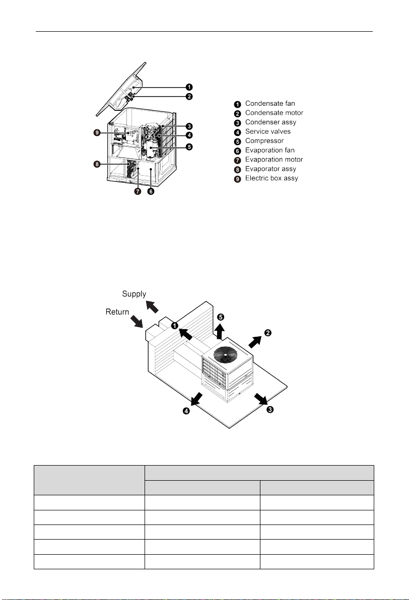
The compact design, attractive appearance, outstanding anti-rust cabinet and
quiet operation make these units suitable for homes, offices, restaurants,
residences or similar places.
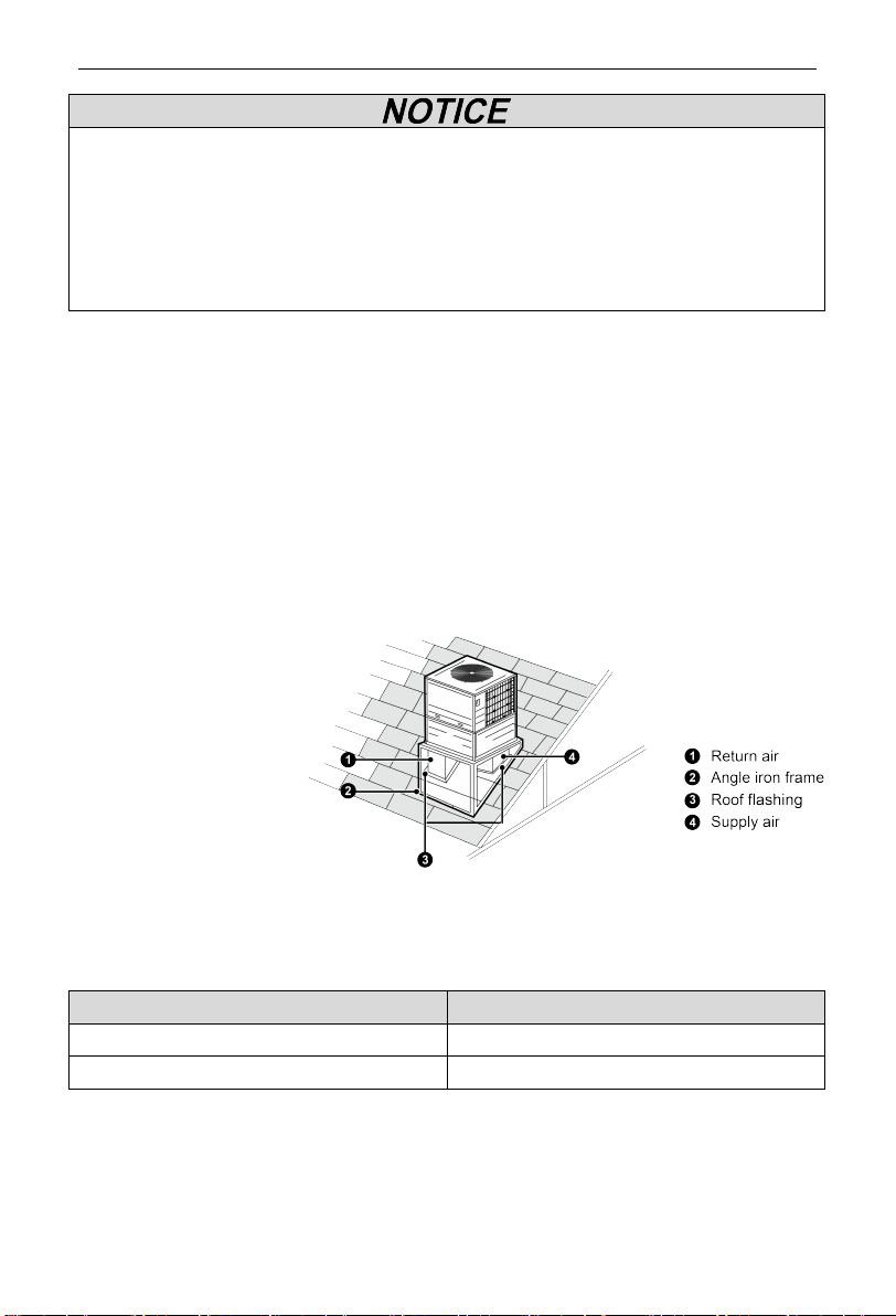
Fig.1
2.2 Operating Range
Mode
Outdoor Condition (DB Temperature )
Cooling
23°F(-5°C) ~ 125°F (52°C)
Heating
-22°F (-30°C) ~ 75.2°F (24°C)
DC Inverter Rooftop Packaged Air Conditioner
5
2.3 Standard Accessory Parts
The standard accessory parts listed below are furnished and should be used as
required.
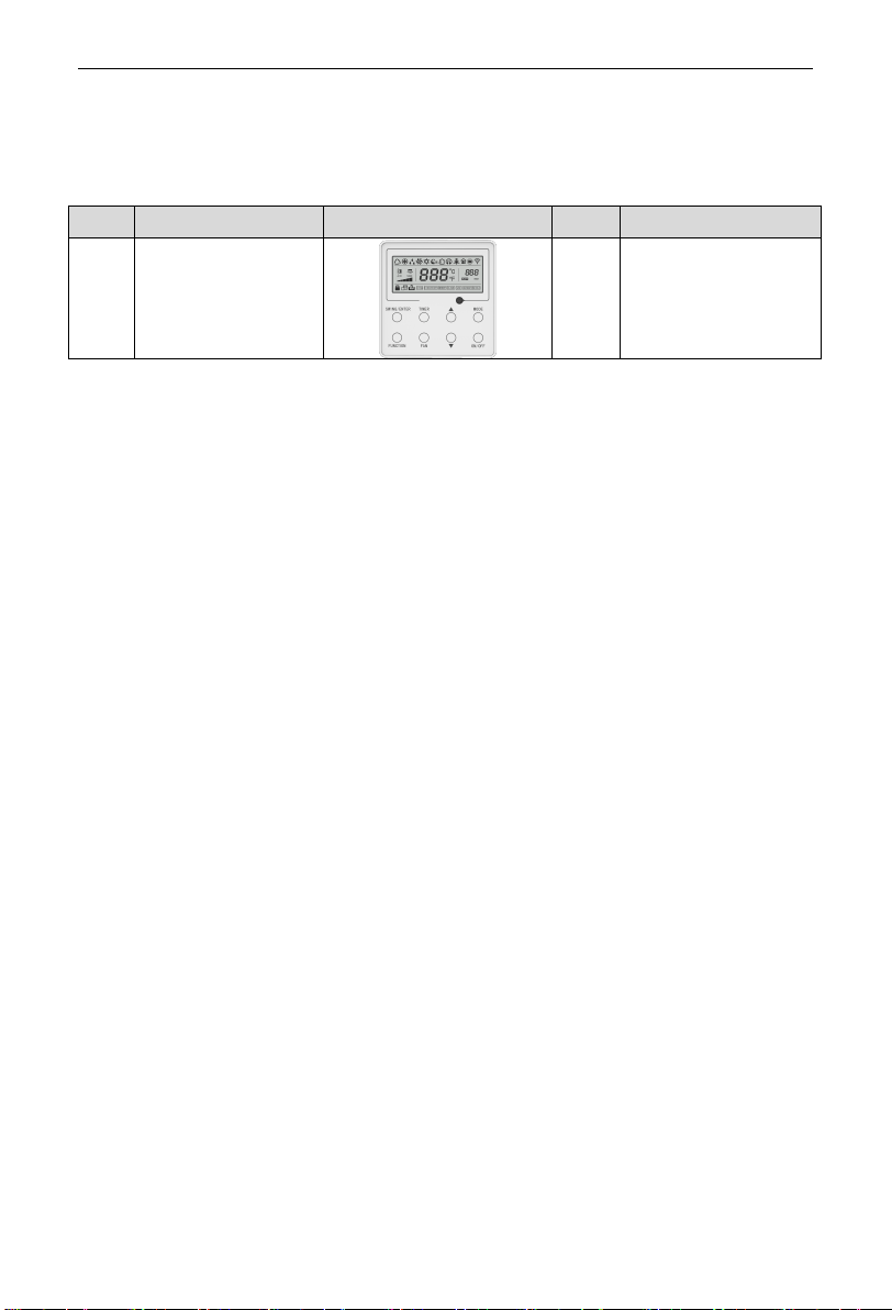
No. Name Appearance Q'ty Usage
1 Wired controller 1 To control the unit
3 Installation
3.1 Installation Preparation
3.1.1 Checking Product Received
After receiving the product, please check if there is any damage caused by
transportation. Shipping damage is the responsibility of the carrier. Verify the model
number, specifications and accessories are correct prior to installation. The
distributor or manufacturer will not accept claims from dealers for transportation
damage or installation of incorrectly shipped units.
3.1.2 Before Installation
Carefully read all instructions for the installation prior to installing product. Make
sure each step or procedure is understood and any special considerations are taken
into account before starting installation. Assemble all tools, hardware and supplies
needed to complete the installation. Some items may need to be purchased locally.
Make sure everything needed to install the product is on hand before starting.
3.1.3 Codes & Regulations
This product is designed and manufactured to comply with national codes. It is
installer’s responsibilities to install the product in accordance with such codes
and/or any prevailing local codes/regulations. The manufacturer assumes no
responsibilities for equipment installed in violation of any codes or regulations.
3.1.4 Replacement Parts
When reporting shortages or damages, or ordering repair parts, give the
complete product model and serial numbers as stamped on the product.
Replacement parts for this product are available through your contractor or local
distributor.
DC Inverter Rooftop Packaged Air Conditioner
6
3.1.5 Selection of Installation Location
①
The unit must be installed where strong enough to withstand the weight of the
unit and fixed securely, otherwise the unit would topple or fall off.
②
Do not install where there is the danger of combustible gas leakage.
③
Do not install the unit at a place with leakage of inflammable gas.
Selection of installation location (Select a location pursuant to the following
condition).
(1) Noise and air flow produced by the air conditioner will not disturb the
neighbors.
(2) Select a location that is safe and away from animals and plants. If not,
please add safety fences to protect the unit.
(3) Install at a place with good ventilation. Make sure the air conditioner stays
at a well-ventilated place with no obstacles nearby that may obstruct the
air inlet and outlet.
(4) The installation location should be able to withstand the weight and
vibration of air conditioner and allow the installation to be carried out
safely.
(5) Avoid installing at a place with leakage of inflammable gas, oil smoke or
corrosive gas.
(6) Keep it away from strong wind because strong wind will affect the
condenser fan and lead to insufficient air flow volume and thus affecting
the unit’s performance.
(7) Away from any object that may get the air conditioner generating noise.
(8) Install the air conditioner at a place where condensate can be easily
drained.
(9) Do not install the air conditioner near the bedroom, otherwise the noise of
the unit operation may disturbing to building occupants.
(10) Do not install the air conditioner where water, ice or snow from overhang
or roof may damage or flood the unit.

DC Inverter Rooftop Packaged Air Conditioner
7
Fig.2
(11) Do not install the air conditioner in a corrosive environment, otherwise it
may shorten the life, or negatively affect the performance of the unit.
(12) Installation requirements in snowy areas:
a) Install the air conditioner on a stand which more than 20 in.(500mm)
higher than the expected snow fall to prevent it from being covered by
snow.
b) Attach snow hood and snow guard.
c) Do not install the air conditioner at a place where a snowdrift is
generated.
d) Remove the air inlet grille to prevent snow from accumulating on it.
Unit:inch(mm)
Fig.3

DC Inverter Rooftop Packaged Air Conditioner
8
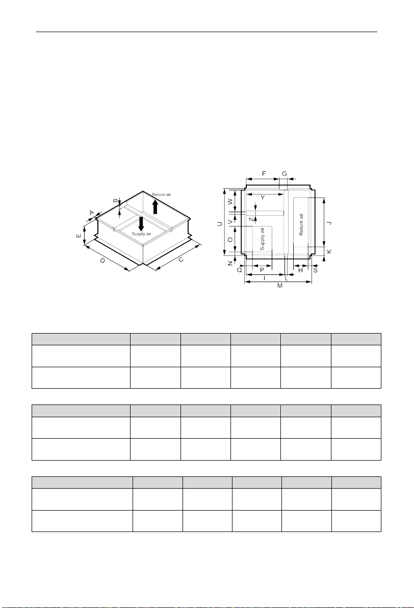
3.1.6 Physical Dimension
Fig.4
Unit:inch(mm)
Dimension
A
B
C
D
$K-H05TC/NaA-T(U)
$K-H04TC/NaA-T(U)
49-1/4
(1250)
44
(1120)
44
(1120)
2-1/2
(65)
Side air vents
E
size of air return
G I
size of air supply
K
F
H
J
L
4
(101)
15-3/8
(390)
16-1/2
(420)
3-3/8
(87)
4
(101)
15-3/8
(390)
11-3/4
(300)
6-1/2
(166)
Buttom air vents
M size of air return O R size of air supply S
N P Q T
7-7/8
(199)
28
(711)
9
(228)
3-3/4
(96)
6-1/2
(166)
11-3/4
(300)
15-3/8
(390)
4
(103)
Dimension
A
B
C
D
$K-H03TC/NaA-T(U)
$K-H02TC/NaA-T(U)
49-1/4
(1250)
44
(1120)
35-7/16
(900)
2-1/2
(65)
Side air vents
E size of air return G I size of air supply K
F H J L
4-7/16
(113)
17-8/16
(445)
16-9/16
(420)
3-7/16
(87)
3-15/16
(101)
15-6/16
(390)
11-13/16
(300)
6-3/16
(157)
Buttom air vents
M
size of air return
O R
size of air supply
S
N P Q T
5-14/16
(149)
23-1/16
(586)
8-10/16
(219)
3-11/16
(93)
6-3/16
(156)
11-14/16
(302)
13-12/16
(350)
3-10/16
(92)
NOTE: Above diagrams may be different from actual mode.
DC Inverter Rooftop Packaged Air Conditioner
9
3.1.7 Names of Main Parts
Fig.5
3.1.8 Diagram of Unit Installation Space and Location
Diagram of installation space and location (Notice: for best performance of the
unit, make sure its installation space conforms to the following installation
dimensions).
Fig.6
NOTE: Above diagrams may be different from actual model.
DIMENSION(Minimum) Installation Clearances
inch
mm
1 24 610
2
8
203
3
20
508
4
24
610
5
60
1524
DC Inverter Rooftop Packaged Air Conditioner
10
NOTE: Refer to local code requirements for additional clearance requirements.
3.2 Unit Installation
3.2.1 Curb-mounted installation
①Install curb.
NOTE: The manufacturer does not supply roof curb. Please refer to Figure 7 for roof
curb reference dimensions.
Fig.7 $K-H05TC/NaA-T(U),$K-H04TC/NaA-T(U),
$K-H03TC/NaA-T(U),$K-H02TC/NaA-T(U)
Unit:inch(mm)
Dimension A
B
C
D
E
$K-H05TC/NaA-T(U)
$K-H04TC/NaA-T(U)
1
(25)
2-11/16
(68)
38-7/16
(976)
38-7/16
(976)
14
(356)
$K-H03TC/NaA-T(U)
$K-H02TC/NaA-T(U)
1
(25)
2-11/16
(68)
38-7/16
(976)
29-3/4
(756)
14
(356)
Dimension F
G
H
I
J
$K-H05TC/NaA-T(U)
$K-H04TC/NaA-T(U)
20
(506)
5
(125)
8-3/4
(223)
23-1/4
(590)
29-1/2
(750)
$K-H03TC/NaA-T(U)
$K-H02TC/NaA-T(U)
20
(506)
5
(125)
8-5/8
(219)
23-1/4
(590)
23
(586)
Dimension
K
L
M
N
O
$K-H05TC/NaA-T(U)
$K-H04TC/NaA-T(U)
5-1/4
(133)
1-9/16
(40)
40-3/8
(1026)
2-3/16
(56)
15-3/8
(390)
$K-H03TC/NaA-T(U)
$K-H02TC/NaA-T(U)
4
(102)
1-9/16
(40)
40-3/8
(1026)
1-3/4
(45)
13-3/4
(350)

DC Inverter Rooftop Packaged Air Conditioner
11
Dimension
P
Q
S
U
V
$K-H05TC/NaA-T(U)
$K-H04TC/NaA-T(U)
11-13/16
(300)
4-11/16
(119.5)
2-3/16
(55)
40-3/8
(1026)
1-7/16
(36)
$K-H03TC/NaA-T(U)
$K-H02TC/NaA-T(U)
11-7/8
(302)
4-1/4
(109)
1-3/4
(46)
31-3/4
(806)
1-7/16
(36)
Dimension W Z Y
$K-H05TC/NaA-T(U)
$K-H04TC/NaA-T(U)
13-3/16
(335)
2-3/4
(70)
22-5/8
(575)
$K-H03TC/NaA-T(U)
$K-H02TC/NaA-T(U)
11-1/4
(285)
2-3/4
(70)
22-5/8
(575)
②Field fabricate ductwork inside curb. Secure supply and return ducts to roof
curb and building structure.
③Rig and place unit.
④Convert unit to vertical duct connection.
⑤Install condensate drain piping.
⑥Make electrical connections.
3.2.2 Pad-mounted installation
①Prepare pad and unit supports.
②Rig and place unit.
③Convert unit to horizontal duct connection.
④Field fabricate ductwork at unit duct openings.
⑤Install condensate drain piping.
⑥Make electrical connections.
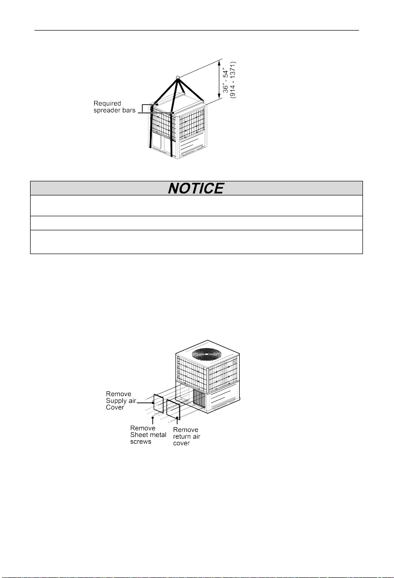
3.2.3 Rigging and Lifting
Do not remove the unit’s package materials before installation. Keep unit
upright and do not drop. Rig the unit by attaching chain or cable slings to the lifting
holes in base rails.
Place the unit on roof curb and maintain the clearance between the roof curb
and the base rail inside at 1/4inch. (6.4mm)
After unit is position, remove rigging skids and package materials.
DC Inverter Rooftop Packaged Air Conditioner
12
Unit:inch(mm)
Fig.8
(1) Spreader bars must required in order to prevent rigging straps from damaging
unit.
(2) All panels must be in place when rigging.
(3) The height between the top of unit and the rigging cables’ connection point
should be 36-54inch (914-1371mm).
3.2.4 Horizontal duct and Vertical duct conversation
To convert to horizontal duct configuration, remove screws from side duct
opening covers (see Fig. 9) and remove covers.
To convert to vertical duct configuration, remove screws from basepan duct
opening covers (see Fig. 10) and remove covers.
Fig.9 horizontal duct

DC Inverter Rooftop Packaged Air Conditioner
13
Fig.10 vertical duct
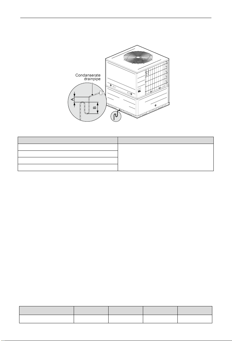
3.2.5 Installation of Condensate Pipe
(1) Condensate drain side is pitched lower than the opposite side. (see Fig.
11)
(2) When shipped out from factory, both the condensate outlets are blocked
by rubber plug. So before installation, please take the rubber plug out.
(3) Condensate removal is performed by attaching a PVC pipe to the drain
pan and terminated in accordance with local or state Plumbing/HVAC
codes.
(4) The condensate pipe shall be installed with an inclining angel of 5~10°, so
as to facilitate the drainage of condensate.
(5) As the inside of the unit is in the negative pressure status, it is required to
set up a backwater elbow. The requirements is: A=B≥P/10+20(mm)
(6) P is the absolute pressure inside the unit. The unit of the pressure is Pa.
(7) After the electrical installation is completed, carry out the testing of the
drainage system.
(8) It is not allowed to connect the condensate drain pipe into waste pipe or
other pipelines which are likely to produce corrosive or peculiar smell to
prevent the smell from entering indoors or corrupt the unit.
(9) It is not allowed to connect the condensate drain pipe into rain pipe to
prevent rain water from pouring in and cause property loss or personal
injury.
(10) Condensate drain pipe should be connected into special drain system for
air conditioner.
(11) Drain hose is in negative pressure state: A = B≥P/10+13/16"(20mm).
(12) Drain hose is in positive pressure state: A≥1-13/16 "(30mm) ,
DC Inverter Rooftop Packaged Air Conditioner
14
B≥P/10+13/16"(20mm).
Unit:inch(mm)
Fig.11
Model
Drain connection size(inch)
$K-H05TC/NaA-T(U)
3/4"(NPT)
AK-H04TC/NaA-T(U)
$K-H03TC/NaA-T(U)
AK-H02TC/NaA-T(U)
3.2.6 Dip Switch Instruction
The unit can be connected to a wired controller or a thermostat, and only one of
them can be connected. When the dip switch SA1 is 0000, the operation command
of the wired controller is valid for the unit; When the dip switch SA1 is not 0000, the
thermostat operation command is valid for the unit and it is not support to the unit
connected to the centralized controller.
The unit is equipped with a wired controller as standard, and the default setting
of the dip switch SA1 is 0000. When it is necessary to replace the thermostat, the
dip switch SA1 should be dialed according to the required speed when the air
conditioner is powered off.
3.2.6.1 Fan Speed Adjustment Guidance
When the wired controller connected with the unit (dip switch SA1:0000),
different static pressure levels can be adjusted, and the fan speeds of different static
pressure levels are as follows:
Static pressure level Super High Middle Low
04 Speed 8 Speed 6 Speed 5 Speed 4
DC Inverter Rooftop Packaged Air Conditioner
15
Static pressure level
Super
High
Middle
Low
05 Speed 9 Speed 7 Speed 6 Speed 5
06 Speed 10 Speed 8 Speed 7 Speed 6
07 Speed 11 Speed 9 Speed 8 Speed 7
08 Speed 12 Speed 10 Speed 9 Speed 8
09 Speed 13 Speed 11 Speed 10 Speed 9
The default static pressure level from factory of the unit is 05, different static
pressure levels can be adjusted according to the need. When the unit is off ,
pressing the "FUNCTION" and "TIMER" button at the same time for 5 seconds can
enter the system debugging function. Then pressing the "MODE" button adjust the
static pressure level to make the center of the wired controller’s display interface
show 11, and then pressing "▲" or "▼" button to show different numbers (01, 02, 03,
04, 05, 06, 07, 08, 09) on the lower right corner of the wired controller’s display
interface. After selecting the appropriate static pressure according to the required
speed, the setting confirmed from pressing the "SWING/ENTER" button.
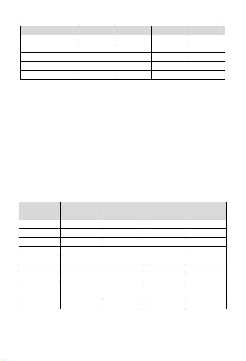
When the unit is connected to the thermostat, the dip switch SA1 is not 0000.
Setting different positions of the dip switch is correspond to different speeds, and
each combination is correspond to a speed. The relationship between combination
and speeds are as follows:
Level Dip switch SA1
4 3 2 1
Speed 4 0 1 0 0
Speed 5 0 1 0 1
Speed 6 0 1 1 0
Speed 7 0 1 1 1
Speed 8 1 0 0 0
Speed 9 1 0 0 1
Speed 10 1 0 1 0
Speed 11 1 0 1 1
Speed 12 1 1 0 0
Speed 13 1 1 0 1
NOTE: 0 means dip switch to ‘on’, 1 means dip switch to number.
3.2.6.2 Fan Performance Data
External static pressure should stay within the minimum and maximum limits
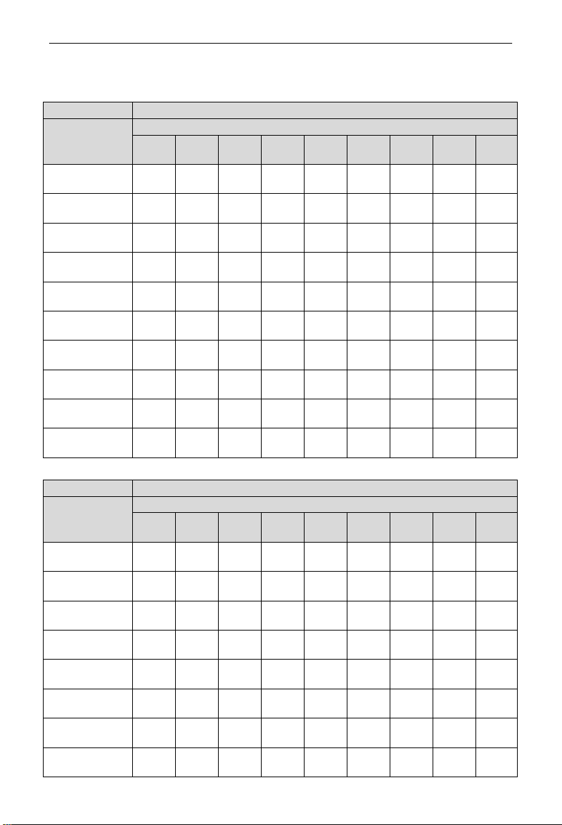
DC Inverter Rooftop Packaged Air Conditioner
16
shown in the table below in order to ensure proper operation of both cooling,
heating, and electric heating operation.
Model
AK-H05TC/NaA-T(U),AK-H04TC/NaA-T(U)
Level
Static pressure:Inches W.C.(Pa)
0
(0)
0.1
(25)
0.2
(50)
0.3
(75)
0.4
(100)
0.5
(125)
0.6
(150)
0.7
(175)
0.8
(200)
Speed 4
(CFM)
1517 / / / / / / / /
Speed 5
(CFM)
- 1464 / / / / / / /
Speed 6
(CFM)
- 1533 / / / / / / /
Speed 7
(CFM)
- - 1517 / / / / / /
Speed 8
(CFM)
- - 1533 / / / / / /
Speed 9
(CFM)
- - - 1525 / / / / /
Speed 10
(CFM)
- - - - 1517 / / / /
Speed 11
(CFM)
- - - - - 1558 1492 / /
Speed 12
(CFM)
- - - - - 1566 1525 1480 /
Speed 13
(CFM)
- - - - - 1591 1538 1497 1470
Model
AK-H03TC/NaA-T(U),AK-H02TC/NaA-T(U)
Level
Static pressure:Inches W.C.(Pa)
0
(0)
0.1
(25)
0.2
(50)
0.3
(75)
0.4
(100)
0.5
(125)
0.6
(150)
0.7
(175)
0.8
(200)
Speed 4
(CFM)
1216 - - - - - - - -
Speed 5
(CFM)
1293 - - - - - - - -
Speed 6
(CFM)
1368 1264 - - - - - - -
Speed 7
(CFM)
1447 1348 1230 - - - - - -
Speed 8
(CFM)
1501 1436 1327 1195 - - - - -
Speed 9
(CFM)
1506 1464 1417 1383 - - - - -
Speed 10
(CFM)
1498 1466 1423 1378 1280 - - - -
Speed 11
(CFM)
1514 1472 1424 1385 1344 1303 - - -
This manual suits for next models
3
Table of contents
Other ACPro Inverter manuals


Popular Inverter manuals by other brands

Sealey
Sealey MW100 instructions

Generac Power Systems
Generac Power Systems Liquid Cooled Gas Engine Generator Sets None Specification sheet

Shindaiwa
Shindaiwa DGW200MS/UK Operator's manual

Fracarro
Fracarro D-Matrix 4S operating instructions

Humless
Humless CampPower SIM-700 user manual

SMA
SMA Sunny Boy 850 Quick installation guide


