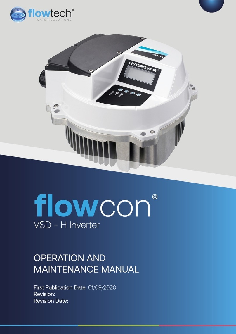
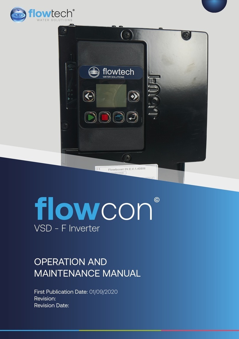
FLOWTECH 103 User manual

1
First Publication Date: 01/09/2020
Revision:
Revision Date:
OPERATION AND
MAINTENANCE MANUAL
VSD - G Inverter
flow
con
©

CONTENTS
OPERATION & MAINTENANCE
General Information 3
Safety Information 4
Safety Warnings & Precautions 5
Customer / Contractor Responsibilities 6
Protection of the environment 7
Sites exposed to ionizing radiations 7
Transportation and Storage 7
Unit handling 7
Storage 8
Technical Description 8
Motor data plate 9
Motor type definition code 9
Pump Data Plate 10
Design and layout 10
Mechanical installation 12
Operation 19
Control panel 20
LEDs description 21
Parameters menu visualization 23
Technical references 30
Troubleshooting 32
Alarm codes 33
Error codes 34
Technical Data 35
Dimensions and weights 36
2

Definitions of Safety Warnings and
Precautions
WARNING!
Indicates a potentially hazardous situation which, if
not avoided, can result in serious injury or death.
CAUTION!
Indicates a potentially hazardous situation which, if
not avoided. Can result in minor to moderate injury, or
serious damage to the product.
General
Information
These instructions are to assist in the installation of the flowcon VSD - G Inverter please follow
them carefully.
If, having read this Operation & Maintenance Manual, there is any doubt about any aspect of
the installation please don't hesitate to contact our technical team.
flowcon VSD - G Inverter
3

Safety
Information
It is essential that correct and safe working practices are adhered to at all times when installing,
operating and/or maintaining any piece of equipment. Always consult safety data sheets, operating
and maintenance manuals, Health & Safety legislation and recommendations and specific
requirements of any equipment manufacturer, site controller, building manager or any other persons
or organisation relating to the procurement, installation, operation and/or maintenance of any piece
of equipment associated or in conjunction with any product provided by flowech Water Solutions.
This document is intended for ALL installers, operators, users and persons carrying out maintenance
of this equipment and must be kept with the equipment, for the life of the equipment and made
available to all persons at all times. Prior to carrying out any work associated with the set it is essential
that the following sheets are read, fully understood and adhered to at all times.
Equipment must only be installed, operated, used, and/or maintained by a competent person. A
competent person is someone who is technically competent and familiar with all safety practices
and all of the hazards involved.
Any damage caused to any equipment by misapplication, mishandling or misuse could lead to risk of
Electrocution, Burns, Fire, Flooding, death or injury to people and/or damage to property dependent
upon the circumstances involved. flowech Water Solutions accepts no responsibility or liability for
any damage, losses, injury, fatalities or consequences of any kind due to misapplication, mishandling
or misuse of any equipment, or as a result of failure to comply with this manual.
Failure to install, operate, use or maintain the equipment in accordance with the information contained
within this document could cause damage to the equipment and any other equipment subsequently
connected to it, invalidating any warranties provided by flowech Water Solutions to the buyer.
4

Safety Warnings &
Precautions
These instructions should be read and clearly understood before working on the system. Please
read this manual carefully and all of the warning signs aached before installing or operating the
equipment keep this manual handy for your reference. This equipment should be installed, adjusted
and serviced by trained and qualified personnel. Failure to observe this precaution could result in
bodily injury.
WARNING! - Install an emergency stop key separately from the isolator. Rotating
shas can be hazardous.
WARNING! - This equipment has a high leakage current and must be permanently
fixed to earth.
WARNING! - Do not aach or remove wiring or connectors when the power is applied.
Do not check signals during operation. When the power is turned on and the running
command is on, the motor will start rotating. The stop key is only eective when the
function is set. If there is a power failure and an operation instruction is given the unit
may start automatically when the power is reinstated.
WARNING! - Make sure that the input voltage is correct. Be sure to install the unit in
a room that is not exposed to direct sunlight and is well ventilated.
Avoid environments which have a high ambient temperature, high humidity or
excessive condensation. Avoid dust. Corrosive gas, explosive gas, inflammable gas,
grinding-fluid mist and salt damage, etc.
WARNING! - Do not connect the power source to any terminals except power
connectors.
WARNING! - Motor control equipment and electronic controllers are connected to
hazardous line voltages. When servicing drives and electronic controllers, you may be
exposed to components at or above the line potential. Extreme care should he taken
to protect against shock. Dangerous voltage may exist aer the power light is o.
Wait more than 5 minutes aer turning o the power supply before performing
maintenance or inspection. Hazard of electric shock. Disconnect incoming power
before working on this unit.
WARNING! - The inverter should be protected separately against ground fault.
Observe the regional regulations for electrical installation!
flowcon VSD - G Inverter
5

Customer / Contractor
RESPONSIBILITIES
It is the responsibility of the customer and/or the contractor:
• To ensure that anyone working on the equipment is wearing all necessary protective gear
and/or clothing.
• Is aware of appropriate health & safety warnings.
• Has read the information in this section of the manual.
CAUTION! - It is strongly recommended that all electrical equipment conforms
to National Electrical Codes and local regulations. Only qualified personnel should
perform installation, alignment and maintenance. The manufacturer reserves the right
to alter the technical data in order to make improvements or update information.
CAUTION! - Failure to observe these rules will render the guarantee invalid. The same
applies to repair jobs and/or replacement. Your legal rights are not aected.
CAUTION! - The manufacturer declines all responsibility in the event of damage or
injury caused as a result of tampering with the equipment.
CAUTION! - Do not switch on/o power supply to run/stop the motor/system! Start
the unit only by using run buon or external run command.
6

Protection of the environment
Disposal of packaging and product
Comply with the current regulations on sorted waste disposal.
Sites exposed to ionizing radiations
If the product has been exposed to ionizing radiations, implement the necessary safety measures for the
protection of people. If the product needs to be despatched, inform the carrier and the recipient accordingly,
so that appropriate safety measures can be put in place.
Spare parts
When contacting Flowtech to request technical information or spare parts, always indicate the product type
and code.
Product warranty
For information on the warranty refer to the documentation of the sale contract.
Transportation and Storage
Packaging inspection
1. Check that quantity, descriptions and product codes match the order.
2. Check the packaging for any damage or missing components.
3. In case of immediately detectable damage or missing parts:
• Accept the goods with reserve, indicating any findings on the transport document, or
• Reject the goods, indicating the reason on the transport document.
• In both cases, promptly contact Flowtech from whom the product was purchased.
Unpacking and inspection of the unit
1. Remove packing materials from the product.
2. Release the product by removing the screws and/or cuing the straps, if fied.
CAUTION: Cut and abrasion hazard
Always wear personal protective equipment.
3. Check the product for integrity and to make sure that there are no missing components.
4. In case of damage or missing components, promptly contact Flowtech.
Unit handling
The unit must be harnessed and lied as shown in Figure 1.
• The product and its components may be heavy: risk of crushing
• Always wear personal protective equipment
• Manual handling of the product and its components must be in compliance with the current
regulations on “manual load handling”, to avoid unfavourable ergonomic conditions causing
• risks of back-spine injury.
• Use cranes, ropes, liing straps, hooks and clasps that comply with current regulations and that are
suitable for the specific use
• Make sure that the harnessing does not damage the unit
• During the liing operations, always avoid sudden movements that could compromise the stability of
the load
• During handling, make sure to avoid injury to people and animals, and/or damage to property.
flowcon VSD - G Inverter
7

Figure 1: Liing
Storage
The product must be stored:
• In a covered and dry place
• Away from heat sources
• Protected from dirt
• Protected from vibrations
• At an ambient temperature between -25°C and +65°C (-13°F and 149°F), and relative humidity
between 5% and 95%.
• Do not place heavy loads on top of the product
• Protect the product from collisions.
Technical Description
Designation
Variable speed pump unit, vertical/horizontal, multi-stage, non self-priming.
Data plates
The data plate is a label showing:
• The main product details
• The identification code
Approval and certifications
For the approvals see the motor data plate:
8

Motor data plate
Figure 2: Motor data plate
1. Type definition code 15. Duty type
2. Rated voltage 16. Enclosure type (NEMA)
3. Rated frequency 17. Weight
4. Rated power [kW] 18. Protection class
5. Rated power [HP] 19. Sha power
6. Part number 20. Voltage
7. Insulation class 21. Current
8. Serial number 22. Part number
9. Maximum ambient temperature 23. Serial number
10. Power factor 24. Power factor
11. Rated current 25. Speed
12. Motor drive eciency 26. Power drive system eciency class (to EN 50598-2)
13. Full power speed range 27. Full load eciency
14. Code leer for locked rotor
Motor type definition code
1. Series
2. Motor frame dimension 90R: Oversized Flange
80: Standard Flange
3. Sha extension □□: Standard sha extension
S8: Custom Sha extension
4. Power supply 1: single phase power supply
3: three phase power supply
5. Sha power•10 [kW] 03: 0.37kW (0.50HP)
05: 0.55 kW (0.75 HP)
07: 0.75 kW (1.00 HP)
11: 1.10 kW (1.50 HP)
15: 1.50 kW (2.00 HP)
22: 2.20 kW (3.00 HP)
6. Motor frame arrangement SVE: Flange with tapped holes and sha w/o keyseat
B14: Flange with tapped holes
B5: Flange with free holes
HMHA: Suitable for 1-5 HM monolithic pumps
HMHB: Suitable for 1-5 HM pumps w/sleeve
HMVB: Suitable for 1-5 VM pumps
flowcon VSD - G Inverter
9

HMHC: Suitable for 10-22 HM pumps
HMVC: Suitable for 10-22 VM pumps
LNEE: Suitable for In-Line pumps
56J: Compliant to NEMA 56 Jet standard
56C: Compliant to NEMA 56C standard
7. Reference market □□: Standard
EU:EMEA
8. Voltage 208-240 : 208-240VAC 50/60Hz
380-460 : 380-460VAC 50/60Hz
230/400: 208-240/380-460VAC 50/60Hz
Pump Data Plate
Figure 4: data plate
1. Head range 9. Maximum operating ambient temperature
2. Flow range 10. Minimum head (EN 60335-2-41)
3. Pump/electric pump unit type definition
code
11. Maximum operating pressure
4. Protection class 12. Electric pump unit weight
5. Frequency 13. Electric pump unit absorbed power
6. Serial number (date + progressive number) 14. Electrical data
7. Electric pump unit/pump part number 15. Maximum operating liquid temperature (uses other
than as EN 60335-2-41)
8. Maximum operating liquid temperature
(uses as EN60335-2-41)
Design and layout
The unit can be fied with the features the application requires
Figure 9: Main components - Single-phase and three-phase models
10

Table 1: Description of components
Position
number
Description Tightening torque ±15%
[Nm] [in•lbs]
1 Screw 1.4 12.4
2 Terminal Box Cover - -
3 Optional module with strip - -
4 M12 I/O cable gland 2.0 17.7
5 M20 cable gland for power supply cables 2.7 23.9
6 M16 I/O cable gland 2.8 24.8
7 Drive (single-phase model) - -
8 Motor - -
9 Screw 6.0 53.1
10 Drive (three-phase model) - -
11 Spacer - -
Pre-assembled ex factory components
Table 2: Included components
Component Quantity Notes
Plug for Cable
Gland
M12 3
M16 1
M20 1
Cable gland and
lock nut
M12 3 Cable Outer Diameter: 3.7 to 7.0 mm (0.145-0.275 in)
M16 1 4.5 to 10.0 mm (0.177-0.394 in)
Cable Gland M20 1 7.0 to 13.0 mm (0.275-0.512 in)
Optional components
Table 3: Optional components
Component Description
Sensors The following sensors can be used with the unit:
Level-sensor
RS485 Module For the connection of a multi-pump system to a supervision system, via
cable (Modb us or BACnet MS/TP protocol)
Wireless Module To connect and interact wireless with e-SM Drive
Adaptor M20 Metric to 1/2” NPT Adapter
The product can be used to pump:
• cold water
• Hot water
The variable speed pump units are made for the following applications:
• Pressure, level, and flow regulation (open loop systems)
• Single or multi pump irrigation systems.
Actuator (constant speed)
The unit operates as an actuator according to speed set point; this is done through user interface, the
corresponding analog input or the communication bus.
Controller (constant pressure)
This mode is set as the default operating mode, and is used for single pump operating units.
Cascade serial / Cascade synchronous
The units are connected via the RS485 interface and communicate via the provided protocol. The
flowcon VSD - G Inverter
11

combination of the dierent units which are used in a multi-pump system depends on the system
requirements.
It is possible to run all pumps in cascade serial mode and cascade synchronous mode as well. If one unit
fails, then each pump of the system can become the lead pump and can take control.
Improper use
The product must not be used for closed loop systems.
Mechanical installation
Installation area
Potentially explosive atmosphere hazard
The operation of the unit in environments with potentially explosive atmospheres or with combustible dusts
(e.g.: wood dust, flour, sugars and grains) is strictly forbidden.
WARNING:
Always wear personal protective equipment
Always use suitable working tools
When selecting the place of installation and connecting the unit to the hydraulic and electric power supplies,
strictly comply with current regulations.
Ensure that the input protection rating of the unit (IP 55, NEMA Type 1) is suitable for the installation
environment.
CAUTION:
Input protection: to ensure the IP55 (NEMA type 1) protection index make sure that the unit is closed correctly.
Before opening the terminal box cover, make sure that there is no water in the unit
Make sure that all unused cable glands and cable holes are correctly sealed
Make sure that the plastic cover is correctly closed
Do not leave the terminal box without cover: risk of damage due to contamination.
Unit installation
See the Quick Startup Guide instructions
Position the unit as shown in Figure 10
Install the unit according to the systems liquid flow.
The arrows on the pump body indicate the flow and the rotation direction
The standard rotation direction is clockwise (looking at the fan cover)
Always install a backflow-prevention device on the suction side.
Always install the pressure sensor on the delivery side, aer the check valve.
Figure 10: Permied positions
12

Outdoor unit installation
In case of outdoor unit installation, ensure appropriate cover (see example in Figure 11).
The size of the cover must be such that the motor is not exposed to snow, rain or direct sunlight;
comply with the guidelines of Table 16.
Figure 11: Outdoor installation
Minimum spacing
Area Model Free Distance
Above the unit 103..105..107..111..115 > 260mm (10.2 in)
Center-distance between
units (to ensure space for
cabling)
103..105..107..111..115 > 260mm (10.2 in)
303..305..307..311..315..322 ≥ 300mm (11.8 in)
Hydraulic installation
Figure 12 and 13 show a single pump system and a multi-pump system respectively.
NOTICE:
If the system is directly connected to the water network, install a minimum pressure switch on the suction
side.
Figure 12: Single-pump system
Figure 13: Multi-pump system
flowcon VSD - G Inverter
13

1. Pump with Motor Drive
2. Diaphragm pressure tank
3. Distribution panel
4.On-o valve
5. Non-return valve
6. Low water control
7. Pressure gauge
8. Pressure sensor
9. Drain tap
Pressure tank
On the pump delivery side there is a membrane expansion vessel, which gives the possibility of maintaining
the pressure inside the piping when the system is not being used. The unit stops the pump from continuing
to run at zero demand and reduce the size of the tank that is required for supply purposes.
Select a vessel suitable for the system pressure, and pre-load it in accordance with the values indicated in the
Quick Startup Guide.
Electrical Installation
The connection to the electric power supply must be completed by an electrician possessing the technical-
professional requirements outlined in the current regulations.
Electrical requirements
Local directives prevail on the specific requirements indicated below.
Electrical connection checklist
• Check that the following requirements are met:
• The electrical leads are protected from high temperature, vibrations, and collisions.
• The current type and voltage of mains connection must correspond to the specifications on the data
plate on the pump.
• The power supply line is provided with:
• A high-sensitivity dierential switch (30 mA) [residual current device RCD] suitable for
earth fault currents with DC or pulsating DC content (a Type B RCD is suggested).
• A mains isolator switch with a contact gap of at least 3 mm.
The electrical control panel checklist
The control panel must match the ratings of the electric pump. Inappropriate combinations do not guarantee
the protection of the unit.
Check that the following requirements are met:
• The control panel must protect the pump against short-circuit. A time lag fuse or a circuit breaker (Type C
model is suggested) can be used to protect the pump.
• The pump has built in overload and thermal protection, no additional overload protection is required.
•
Electrical hazard
Before starting work on the unit, make sure that the unit and the control panel are isolated from the power
supply and cannot be energized.
Grounding (earthing)
• Always connect the external protection conductor to the ground terminal before aempting to make
any other electrical connections
• Connect all the electric accessories of the pump and the motor to the ground, making sure that the
connections are completed correctly
• Check that the protection conductor (ground) is longer than the phase conductors; in case of acci-
dental disconnection of the power supply conductor, the protection conductor (ground) must be the
last one to detach itself from the terminal.
Use a cable with several strands to reduce electric noise.
14

Wire types and ratings
All cables must comply with local and national standards in terms of section and ambient temperature
Use cables with minimum heat resistance +70°C (158°F); to ensure compliance with UL (Underwriters
Laboratories) regulations, all power supply connections must be completed using the following types of
copper cables with minimum resistance +75°C: THW, THWN
Cables must never enter into contact with the motor body, the pump and the piping.
The wires connected to the power supply terminals and the fault signal relay (NO, C) must be separated from
the others by means of reinforced insulation.
Table 4: Electric connection cables
Models Power supply input cable + PR Tightening Torque
Wire numbers
x Max. copper
section
Wire numbers x
Max. AWG
Mains and
motor cable
terminals
Earth
conductor
103, 105, 107,
111,115
3 x 1.5 mm2
3 x 0.0023 sq.in
3 x 15 AWG Spring
connectors
Spring
connectors
303, 305, 307,
311,315, 322
4 x 1.5 mm2
4 x 0.0023 sq.in
4 x 15 AWG 0.8 Nm
7.1 lb-in
3 Nm
26.6 lb-in
Control cables
External volt free contacts must be suitable for switching < 10 VDC.
:
• Install the control cables separate from the power supply cables and the fault signal relay cable
• If the control cables are installed in parallel with the power supply cable or the fault signal relay, the
distance between the cables must exceed 200 mm
• Do not intersect the power supply cables; should this be necessary, a 90°intersection angle is permit-
ted.
Table 5: Recommended control cables
Drive control
cables
Wires number x Max. copper
Section AWG Tightening torque
All I/O conductors 0.75-1.5 mm
0.00012-0.0023 sq.in 18-16 AWG 0.6 Nm
5.4 lb-in
Power supply connection
Contact with electric components may cause death, even aer the unit has been switched o. Before any
interventions on the unit, the network voltage and any other input voltages must be disconnected for the
minimum time indicated in Table 9.
Table 6: Power supply wiring procedure
1. Open the terminal box cover (2) by removing the screws (1). Fig. 9
2. Insert the power cable in the M20 cable gland (5) Fig 14
3. Connect the cable according to the wiring diagram. Fig. 9
Table 7: I/O wiring procedure
1. Open the terminal box cover (2) by removing the screws (1). Fig. 9
2. Connect the cable according to the wiring diagram. Fig. 15
3. Close the cover (2) and tighten the screws (1). Fig. 9
flowcon VSD - G Inverter
15

Figure 14: Wiring diagram
Figure 15: Connection label
Table 8: I/O terminals
16

1~ Item Terminals Ref. Description Notes
Fault Signal C 4 COM - error status relay
NO 5 NO - error status relay
Auxiliary Voltage
Supply
15V 6 Auxiliary voltage supply +15
VDC
15VDC, max. 100 mA
Analog input 0-10V P2IN/S+ 7 Actuator mode 0-10 V input 0-10 VDC
P2C/S- 8 GND for 0-10 V input GND, electronic ground (for
S+)
External Pressure
sensor [also
Dierential]
P1+ 9 Power supply external sensor
+15 VDC
15VDC, max. 100 mA
P1- 10 External sensor 4-20 mA
input
4-20 mA
External Start/Stop Start 11 External ON/OFF input
reference
Default short circuited Pump
is enabled to RUN
Stop 12 External ON/OFF input
External Lack of
Water
Low + 13 Low water input Default short circuited
Lack of water detection:
enabled
Communication bus Low - 14 Low water reference
B1 15 RS485 port 1: RS485-1N B (-) ACT, HCS control mode:
RS 485 port1 for external
communication
MSE, MSY control mode: RS
485 port 1 for multi-pump
systems
A1 16 RS485 port 1: RS485-1P A (+)
GND 17 Electronic GND
B2 18 RS485 port 2: RS485 port 2:
RS485-2N B (-) active only
with optional module
RS 485 port2 for external
communication
A2 19 RS485 port 2: RS485 port 2:
RS485- 2P A (+) active only
with optional module
GND 20 Electronic GND
flowcon VSD - G Inverter
17

3~
Item Terminals Ref. Description Notes
Fault signal C 25 COM - error status relay In case of power cables: use
the M20 cable gland
NO 24 NO - error status relay
Motor running
signal
C 23 Common contact In case of power cables: use
the M20 cable gland
NO 22 Normally open contact
Auxiliary Voltage
Supply 15V 21 Auxiliary voltage supply +15
VDC 15VDC, max. 100 mA
Analog input
0-10V
S+ 20 Actuator mode 0-10 V input 0-10 VDC
S- 19 GND for 0-10 V input GND, electronic ground (for S+)
External Pressure
sensor [also
Dierential]
P1+ 18 Power supply external sensor
+15VDC 15VDC, max. 100 mA
P1- 17 External sensor 4-20 mA
input 4-20 mA
External pressure
sensor
P2+ 16 Power supply external sensor
+15VDC 15VDC, max. 100 mA
P2- 15 Sensor 4-20 mA input 4-20 mA
External Start/
Stop
Start 14 External ON/OFF input Default short circuited Pump is
enabled to RUN
Stop 13 External ON/OFF input
reference
External Lack of
Water
Low+ 12 Low water input Default short circuited Lack of
water detection: enabled
Low- 11 Low water reference
Communication
Bus
B2 10
RS485 port 2: RS485 port 2:
RS485-2N B (-) active only
with optional module RS 485 port2 for external
communication
A2 9
RS485 port 2: RS485 port 2:
RS485-2P A (+) active only
with optional module
GND 8 Electronic GND
B1 7 RS485 port 1: RS485-1N B (-) ACT, HCS control mode:
RS 485 port 1 for external
communication
Control mode MSE, MSY: RS
485 port 1 for multi-pump
systems
A1 6 RS485 port 1: RS485-1P A (+)
GND 5 Electronic GND
18

Operation
In case of co-existence of two or more of the following conditions:
• High ambient temperature
• High water temperature
• Duty points insisting on unit maximum power
• persisting under voltage of mains, may jeopardise the life of the unit, and/or derating may occur: for further
information contact Flowtech.
Wait times
Contact with electric components may cause death, even aer the unit has been switched o. Before any
interventions on the unit, the network voltage and any other input voltages must be disconnected for the
minimum time indicated in Table 9.
Table 9: Wait times
Model Minimum waiting time (min)
103, 105, 107, 111, 115 4
303, 305, 307, 311, 315, 322 5
Frequency converters contain DC-link capacitors that can remain charged even when the frequency
converter is not powered.
To avoid electrical hazards:
• Disconnect the AC power supply
• Disconnect all types of permanent magnet motors
• Disconnect all DC-link remote power supplies, including the baery backups, the
• Uninterrupted Power Supply units and the DC-link connections to other frequency converters
• Wait for the capacitors to discharge completely before carrying out any maintenance or repairs; see
Table 9 for the waiting times
Programming Precautions
• Carefully read and follow the following instructions before starting the programming activities, to avoid
wrong seings that may cause malfunctioning
• All modifications must be done by qualified technicians.
flowcon VSD - G Inverter
19

Control panel
Figure 16: Control panel
Table 10: Description of the control panel
Position number Position number
1 Decrease buon
2 Increase buon
3 START/STOP and menu access buon
4 POWER LED
5 Status LED
6 Speed LED bar
7 Communication LED
8 Unit of measure LEDs
9 Display
Description of the buons
Table 11: Functions of push buons
Push Buon Function
• Main view: decreases the required value for the selected control mode
• Parameter menu: decreases the displayed parameter index
• Parameter view / editing: decreases the value of the displayed parameter
• Zero pressure auto-calibration: automatic calibration of the pressure sensor.
• Main view: increases the required value for the selected control mode
• Parameter menu: increases the displayed parameter index
• Parameter view / editing: increases the value of the displayed parameter
• Zero pressure auto-calibration: automatic calibration of the pressure sensor.
• Main view: START/STOP the pump
• Parameter menu: switches to parameter view / editing
• Parameter view / editing: saves the value of the parameter.
Long press
• Main view: switches to parameter selection
• Parameters Menu: switches to Main Visualization
+
• Main view: alternates between Speed and Head units of measure.
+
• Main view: alternates between Speed and Head units of measure.
20
This manual suits for next models
10
Table of contents
Other FLOWTECH Inverter manuals
Popular Inverter manuals by other brands

YASKAWA
YASKAWA PVI 23 TL Installation and operation manual
GE
GE HOME NERATOR SYSTEM 18000 WATT Installation and start-up manual
Atlas Copco
Atlas Copco QAS366 Gd USA instruction manual

Winco
Winco W6000HE-03/A Installation & operator's manual
Solectria Renewables
Solectria Renewables PVI 13KW Installation and operation manual
Solax
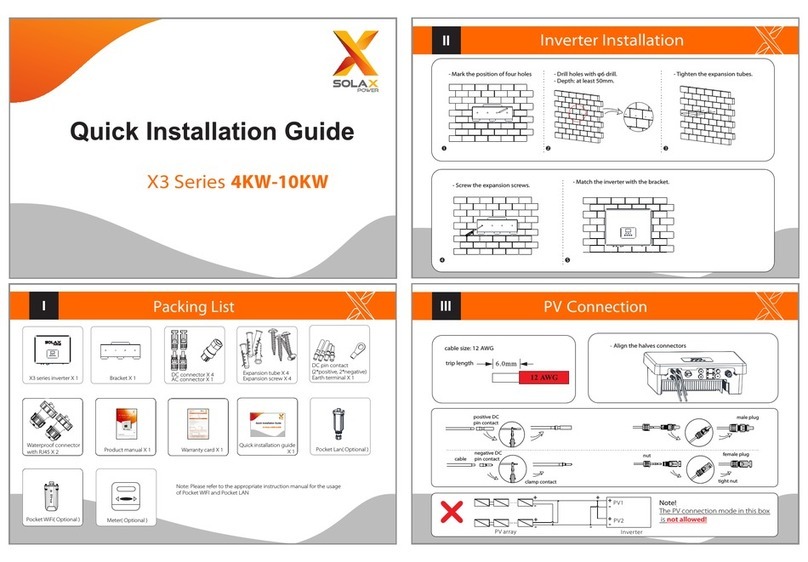
Solax X3 series Quick installation guide
