manuals.online logo
Brands
  1. Home
  2. •
  3. Brands
  4. •
  5. Morningstar
  6. •
  7. Inverter
  8. •
  9. Morningstar SureSine 150 W User manual

Morningstar SureSine 150 W User manual

Quick Start Guide
14
Specifications*:
© 2022 Morningstar Corporation. All Rights Reserved. MS-003785 v1
In the Box:
#10 Mounting
Screws (x4)
Tools Required:
— #2 Philips Screwdriver
— 3/16 (5 mm) & 1/8" (3.8 mm) Flathead
Screwdriver
— Drill with a 1/8" (3.8 mm) bit
— Multimeter
— Crimping Tool
— Wrench
WARNING: Hazardous Voltage
The SureSine Inverter must be installed by a
qualified technician in accordance with the
electrical regulations of the country of
installation.
Scan QR Code to go directly
to the SureSine Inverter
Installation Manual and
warranty information online.
Contact Information:
Technical Support: morningstarcorp.com/support
Phone: 1-215-321-4457
SureSine Inverter
Warranty Registration: https://www.morningstarcorp.com/product-registration/
150 W, 300 W & 700 W Models
(Factory-wired Versions ONLY)
SureSine Inverter Models:
For use with 12 Vdc, 24 Vdc,
or 48 Vdc Systems
CAUTION: This guide must be used with the full product manual that includes important
information. Carefully read the SureSine Inverter product manual for all specifications,
safety, regulatory and warranty information, and for all required instructions on
installation procedures, configuration, and operation.
Battery Voltage 12 Vdc, 24 Vdc, or 48 Vdc
AC Output Voltage (Vac) /
Frequency 120 Vac / 60 Hz, 127 Vac / 60 Hz,
or 230 Vac / 50 Hz
Rated Power Communication
Options
150 W / 300 W / 700 W Remote Switch,
Bluetooth, EIA-485, MS-CAN
AC Interface
Options
North American Type-B Outlet or
UNI Universal AC Outlet
*Partial Specification List only. For the complete list of specifications, see the SureSine Installation and Operation’s Manual.
DIP Switch Settings (Default Settings = OFF):
IMPORTANT:
The SureSine Inverter is designed for
converting DC power to AC power only.
It will not charge batteries.
LED Indications: AC Output Mode Switch:
I
O
II
(Front View)
ON OFF
Press the |Put the switch in
a neutral position
(Side View)
REMOTE
Press the | |
(Side View) (Side View)
(Front View) (Front View)
I
O
II
I
O
II
Terminal Resistor
4-Pin Pluggable
Terminal Connector
No power or Battery
below 9.5 V
OFF
AC Output OFFGREEN
AC Output ONGREEN
AC Standby ModeGREEN
Low Voltage Disconnect
(LVD) Warning
GREEN
Low Voltage Disconnect
(LVD)
GREEN
Recoveragle Fault3
RED
Critical Fault3
RED
OFF
OFF
GREEN
GREEN (BLINK)2
RED (BLINK)2
RED
RED (BLINK)2
RED
Operation or StateSTATUS LED1AC Output LED
1 The Status LED flickers ON very briefly when the LED is OFF. The Status LED flickers OFF
very briefly when the LED is GREEN or RED solid. The "heartbeat" occurs every 5 seconds.
2 0.5 Hz. Rate
3See the SureSine Inverter Installation and
Operations Manual for details.
DIP 2:
ALARM
SOUND
DIP 1:
OPERATIONAL
CONTROL
DIP 3:
NOT USED
DIP 4:
LOW VOLTAGE
DISCONNECT
(LVD)
DIP 5:
LVD PRESETS
DIP 6:
STANDBY
MODE DIP 6 OFF =
AC Output Always ON
DIP 6 ON =
AC Output OFF < 8 W
12345678
12345678
DIP 8:
BLUETOOTH
COMMUNI-
CATIONS
12345678
12345678
12345678
12345678
DIP 8 ON =
Bluetooth Enabled
DIP 8 OFF =
Bluetooth Disabled
12345678
DIP 1 ON =
Digital Control
12345678
DIP 1 OFF = Switch
Control
12345678
DIP 2 ON = Alarm
is Enabled
123 45678
DIP 2 OFF = Alarm
is Disabled
12345678
DIP 4 ON = Presets
12345678
DIP 4 OFF = Custom
12345678
LVD Default Setting (DIP Switch 4 OFF) = 11.8 V, 23.6 V, or 47.2 V
ON Position is Disabled
1 2345678
• For 12 Vdc Systems: DIP 5 OFF = 10.5 V DIP 5 ON = 11.5 V
• For 24 Vdc Systems: DIP 5 OFF = 21.0 V DIP 5 ON = 23.0 V
• For 48 Vdc Systems: DIP 5 OFF = 42.0 V DIP 5 ON = 46.0 V
DIP 7:
12345678
ETHERNET
SECURITY DIP 7 ON = Ethernet
Write Enabled
DIP 7 OFF = Ethernet
Write Disabled
700 W Models ONLY. NOT USED in 150 W or 300 W Models.
12345678
DIP Switch 8 must be set before connecting DC power.
If changed during operation, a power cycle is required.
Default is OFF
5024876
BATTERY (-)
A B
EIA-
485
REMOTE
BATTERY (+)
IN
OUT
MS-CAN
DC Side
32
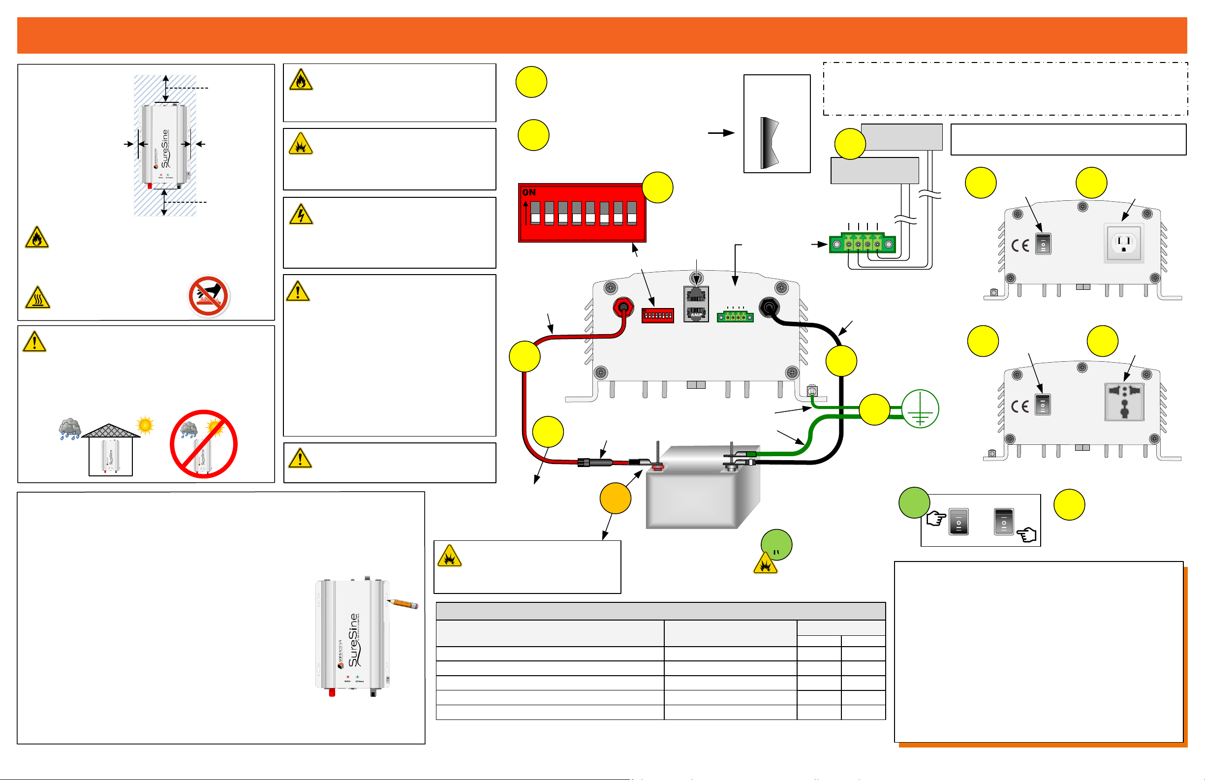
SureSine Inverter Quick Start Guide
Power UP Sequence:
1. Connect Battery/Battery Bank. (STEP 8)
2. Connect AC loads. (STEP 9)
3. Close all circuit breakers, disconnect switches, or insert
fuse into fuse holder. (STEP 10)
4. Put the AC Output Mode Switch in the ON (or REMOTE)
position. (STEP 11)
Power DOWN Sequence:
1. Put the AC Output Mode Switch in the OFF position.
2. Disconnect AC loads.
3. Open all circuit breakers, disconnect switches, remove
fuses from fuse holders.
4. Disconnect Battery/Battery Bank.
Mounting:
Minimum
Clearance
Requirements:
CAUTION: Equipment Damage
Do not expose the SureSine to weather. Locate in a
dry, protected area to prevent equipment damage.
Ensure the minimum clearance requirements are
followed to provide adequate ventilation and prevent
the unit from overheating.
IMPORTANT: Example only. Actual wiring may vary. READ the SureSine
Installation and Operations Manual for mandatory safety requirements. All
configurations must comply with local and national electric codes. Consult the
local electric authority to ensure compliance.
WARNING: Risk of Fire
Do not install over an easily combustible
surface, since the heat sink may get hot
under certain operating conditions.
Step 1: Choose mounting location
A) Determine how and where the inverter will be mounted.
B) Ensure the inverter is protected from sun, rain, and dust.
Step 2: Wiring accessibility and air flow clearance
A) Plan and confirm wire routing-access.
B) Verify that the mounting screws will not penetrate wires or
other objects located on the opposite side of the surface.
C) Verify that there is at least 6" of space around the unit.
Step 3: Mark and drill holes
A) Place the inverter on the wall where the unit will be mounted.
B) With a pencil or pen, mark the center of each keyhole slot;
two (2) on top and two (2) on the bottom.
C) Remove the inverter and drill four (4) 1/8" (3.175 mm) holes
where the marks were made.
Step 4: Secure the inverter
A) Place the SureSine onto the surface and align the keyhole slots
with the four (4) pilot holes.
B) Use the four (4) #10 screws (included) to secure the SureSine to the surface.
DIP Switch Enlargement
12345678
(+) (–)
Battery / Battery Bank
12, 24, or 48 Vdc
Securing
hardware not
shown.
Battery (+)
Battery (–)
Chassis Ground
1NEGATIVE GROUND
(For Positive Ground wiring,
see the SureSine Installation
and Operations Manual)
Fuse or
circuit breaker2
DIP Switches
MS-CAN
Port
DC System Ground1
For DIP Switch settings,
see page 4 of this guide.
A B
EIA-
485
REMOTE
Enlargement
Universal
AC Outlet
North American
B-Type Outlet
230 V / 50 Hz Models
120 V / 60 Hz Models
AC Output
Mode Switch
AC Output
Mode Switch
AC Side
AC Side
See the SureSine Installation and Operation’s
Manual for information on communication options.
EIA-485 &
Remote Switch,
Terminals
Earth
Ground
Ensure circuit breakers are open,
disconnect switches are open, and
fuses are removed from fuse holders.
AND
Ensure the AC Output Mode
Switch is in the OFF position.
STEP
1a
STEP
2
STEP
4
STEP
6
STEP
7
STEP
5
STEP
8
STEP
10
I O II
(Side View)
AC Output
Mode Switch
STEP
1b
STEP
9
STEP
9
2BEFORE INSTALLING:
Ensure the fuse is removed from
the fuse holder or the disconnect
is in the OPEN position.
WARNING: Shock Hazard
Fuses, single-pole circuit breakers or single-pole
disconnect switches should NEVER open
grounded system conductors. This could create
a shock hazard that could be fatal to personnel
and/or damage the equipment.
CAUTION: Equipment Damage
Ensure the AC loads do not exceed the
continuous and surge power ratings.
WARNING: Risk of Fire
All over-current protection devices and wiring
must be sized properly, in accordance with US
National Electric Code (NEC) or the country of
installation’s local regulations.
STEP
1b
STEP
1b
WARNING: Explosion Hazard
Never install the SureSine in an enclosure with
vented/flooded batteries. Battery fumes are
flammable and will corrode and destroy the
SureSine circuits. Ensure sufficient ventilation.
For optimal ventilation
and cooling, mount in
portrait style orientation.
CAUTION: Burn Hazard
Place in a location to avoid
direct contact.
Portrait Orientation
Remote ON/OFF
Switch (Optional)
EIA-485 Device
(Optional)
STEP
3
ON REMOTE
or
STEP
11
*For recommended/minimum wire sizes and disconnect/fuse sizes per application, and terminal block installation
for the remote switch or communications options, see the SureSine Installation and Operations Manual.
20
M8 (~5/16")
35
M6 (~1/4") 20
14 - 2 AWG (2.5 - 10.0 mm2)35
16 - 28 AWG (1.0 - 0.1 mm2)
DC (+) (–) Input Bolt Terminals (150 - 300 Watt)
AC Output Neutral, Line and Ground Terminals
Chassis Ground Lug
Modbus, Remote Switch, Auxiliary Power Terminals
Terminal Size or Wire Size* Torque to:
Terminal
TERMINAL TORQUE REQUIREMENTS
DC (+) (–) Input Bolt Terminals (700 Watt) M6 (~1/4")
5
2.3
4
2.3
4
0.57
In-lbs. Nm
WARNING: Explosion Hazard
STEP 8 can produce a spark if the
fuse is inserted or the disconnect
is in the CLOSED position.
Close all circuit breakers,
disconnect switches, or
insert the fuse into
fuse holder.
STEP
12
Check the LEDs for
proper operational
status indications.
See page 4 of this
guide.
Shown: 150 W or 300 W Models.
The DC Side of the 700 W Model
varies slightly.
6"
(152.4 mm)
6"
(152.4 mm)
1"
(25.4 mm)
1"
(25.4 mm)
IMPORTANT: Neutral-Ground
Bond
The AC Neutral of the 120 Vac/ 60 Hz models
is bonded to the inverter frame internally from
the factory as required for UL safety
requirements.
The AC Neutral of the 127 V, 230 V, and 240 V
models is floating (not bonded to the inverter
frame). If a neutral-ground bond is required an
internal neutral-ground jumper wire (included)
can be used to connect the neutral terminal to
the grounded chassis.
Consult Section 2.8.4 of the manual for
additional information.
Ensure the inverter chassis
is properly bonded to
ground as per Section 2.8.4
of the installation manual.

Other manuals for SureSine 150 W

3

This manual suits for next models

2

Other Morningstar Inverter manuals

Morningstar SureSine 150 W User manual

Morningstar

Morningstar SureSine 150 W User manual

Morningstar SI-300-115V User manual

Morningstar

Morningstar SI-300-115V User manual

Morningstar SureSine 150 W User manual

Morningstar

Morningstar SureSine 150 W User manual

Morningstar TS-MPPT-60-600V-48-DB-TR User manual

Morningstar

Morningstar TS-MPPT-60-600V-48-DB-TR User manual

Morningstar SUNSAVER MPPT SS-MPPT-15L User manual

Morningstar

Morningstar SUNSAVER MPPT SS-MPPT-15L User manual

Morningstar SUNSAVER SS-6-12V User manual

Morningstar

Morningstar SUNSAVER SS-6-12V User manual

Morningstar PS-MPPT-25 User manual

Morningstar

Morningstar PS-MPPT-25 User manual

Morningstar TRISTAR TS-MPPT-60 Instruction Manual

Morningstar

Morningstar TRISTAR TS-MPPT-60 Instruction Manual

Morningstar SureSine-300 Setup guide

Morningstar

Morningstar SureSine-300 Setup guide

Morningstar ProStar PS-15M User manual

Morningstar

Morningstar ProStar PS-15M User manual

Morningstar Tristar TS-MPPT-60M User manual

Morningstar

Morningstar Tristar TS-MPPT-60M User manual

Morningstar SureSine 150 User manual

Morningstar

Morningstar SureSine 150 User manual

Morningstar SureSine 150 W User manual

Morningstar

Morningstar SureSine 150 W User manual

Popular Inverter manuals by other brands

Mitsubishi Electric FR-A8NP instruction manual

Mitsubishi Electric

Mitsubishi Electric FR-A8NP instruction manual

Champion 100136 Operator's manual

Champion

Champion 100136 Operator's manual

Must PV1100 PLUS Series Service manual

Must

Must PV1100 PLUS Series Service manual

Toshiba Q9 True Torque Control2 Adjustable Speed... quick start guide

Toshiba

Toshiba Q9 True Torque Control2 Adjustable Speed... quick start guide

Vanner RE Series owner's manual

Vanner

Vanner RE Series owner's manual

Baldor TS25 Operator's manual

Baldor

Baldor TS25 Operator's manual

Waeco SinePower MSP 162 instruction manual

Waeco

Waeco SinePower MSP 162 instruction manual

EDECOA DPP10 user manual

EDECOA

EDECOA DPP10 user manual

SMA Windy Boy WB 1100LV user manual

SMA

SMA Windy Boy WB 1100LV user manual

ZCS Azzurro HYD3000-ZP1 quick guide

ZCS

ZCS Azzurro HYD3000-ZP1 quick guide

Sofar ME3000SP user manual

Sofar

Sofar ME3000SP user manual

Crafstman 580.327182 Operator's manual

Crafstman

Crafstman 580.327182 Operator's manual

Tabor Electronics 5064 user manual

Tabor Electronics

Tabor Electronics 5064 user manual

Westerbeke 4KW-7.7KW-11KW-12 5KW Operator's manual

Westerbeke

Westerbeke 4KW-7.7KW-11KW-12 5KW Operator's manual

Kipor IG3000E Operator's manual

Kipor

Kipor IG3000E Operator's manual

Mitsubishi Electric i-MTR2-G02-M0 Data book

Mitsubishi Electric

Mitsubishi Electric i-MTR2-G02-M0 Data book

Enercell 150-Watt Power Inverter user guide

Enercell

Enercell 150-Watt Power Inverter user guide

Mitsubishi Electric FR-V5NE-E instruction manual

Mitsubishi Electric

Mitsubishi Electric FR-V5NE-E instruction manual

manuals.online logo
manuals.online logoBrands
  • About & Mission
  • Contact us
  • Privacy Policy
  • Terms and Conditions

Copyright 2025 Manuals.Online. All Rights Reserved.