Acrel ASJ Series Owner's manual

041
ASJ Series Residual Current
Operated Relay
Installation and Operation
Instruction V1.9
Acrel Co., LTD

Declaration
Please read this manual carefully before using these products, in which the involved pictures,
logos, symbols, etc. are all reserved by the Acrel Co., Ltd. Personnel not inside the company shall
not publicly reprint all or part of the contents without written authorization.
Before using the product, please read the tips and precautions in this operation manual, and
Acrel does not take responsibility for personal injuries or economic losses caused by ignoring tips of
this manual;
The contents of the manual will be continuously updated and revised, thus the products
functions in this manual may inevitably have a slight discrepancy with the real objects during the
continuous upgrading process. Users should give first place to the purchased real products, and can
search www. acrel.cn to downloads or through sales channels to obtain the latest version of the
manual.

Contents
1 Introduction........................................................................................................................................1
2 Types of Products...............................................................................................................................1
3 Technical parameters..........................................................................................................................2
4 Installation and connection................................................................................................................2
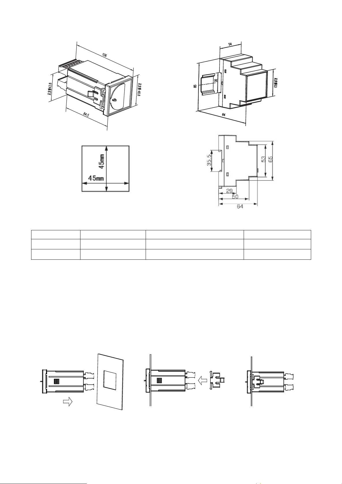
4.1 Shape and Installation Dimensions..........................................................................................2
4.2 Installation Instructions............................................................................................................3
4.2.1 Installation Steps............................................................................................................3
4.2.2 Installation of accessories..............................................................................................4
4.3 Terminals and wiring ...............................................................................................................4
4.4 Matters needing attention.........................................................................................................4
5 Operating Guide.................................................................................................................................5
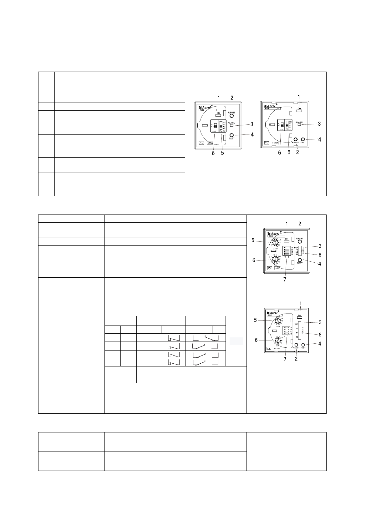
5.1 Description of AC type Panel ..................................................................................................5
5.2 Description of A-type panel.....................................................................................................5
5.3 Description of LCD type panel................................................................................................5
5.4 Description of Selection...........................................................................................................6
5.5 Instructions for the selection of transformer............................................................................7
6 Typical applications ...........................................................................................................................8
7 Programming menu............................................................................................................................8
7.1 Programming Example ............................................................................................................9
7.2 Programming Example ..........................................................................................................12
8 Communication Guide.....................................................................................................................13
8.1 Overview of Communication Protocol..................................................................................13
8.2 Introduction to function code.................................................................................................14
8.3 Communication Address Table..............................................................................................15
9 Ordering example.............................................................................................................................16

1
ASJ series residual current operated relay
1 Introduction
ASJ series residual current operated relay can be combined with low voltage circuit breaker or
low voltage contactor to form a residual current protection device, which is mainly used for the TT
and TN system distribution lines with AC 50Hz and rated voltage of 400V and below. It is used to
protect the electrical circuit form ground faults, prevent equipment damage caused by earth fault
current and electrical fire accidents, and can also be used to provide indirect contact protection
against personal electric shock hazard.
Products meet the requirements of GB/T 22387-2016 residual current operated relay.
2 Types of Products
Type
Function
Installation
Appearance
ASJ10-LD1C
AC-type residual current measurement;
Alarm prompt of current crossing line;
Rated residual operating current can be measured;
Limit non-driving time can be set;
Two sets of relay output;
With local and remote “test”and “reset”functions.
Guide
(DIN
35mm)
ASJ10-LD1A
A-type residual current measurement;
Current percentage light column display;
Rated residual operating current can be measured;
Limit non-driving time can be set;
Two sets of relay output (settable)note 1;
With local and remote “test”and “reset”functions.
ASJ10L-LD1Anote2
A-type residual current measurement;
Rated residual operating current can be measured;
Limit non-driving time can be set;
Two sets of relay output (settable);
Transformer breakage alarm can be set;
Pre-alarm value can be set;
Return value can be set.
With on-site display, remote "test", "reset"
LCD display, 25 event records.
ASJ20-LD1C
AC-type residual current measurement;
Alarm prompt of current crossing line;
Rated residual operating current can be measured;
Limit non-driving time can be set;
Two sets of relay output;
With local and remote “test”and “reset”functions.
Panel
(48*48)

2
ASJ20-LD1A
A-type residual current measurement;
Current percentage light column display;
Rated residual operating current can be measured;
Limit non-driving time can be set;
Two sets of relay output (settable)note 1;
With local and remote “test”and “reset”functions.
Note 1: The function of setting for relay means that you can set the initialization and the output state of relay by yourself through the
code dialing on the panel; the specific setting guide can be found from the chapter 5.2.
Note 2: Optional function, RS485 interface, Modbus-RTU Communication, type is ASJ10L-LD1A/C
3 Technical parameters
Technical Parameter
Indicator
AC type
A type
Power
supply
Voltage range
AC110V、AC220V
(±10%)
AC/DC85~265V
Power dissipation
≤5W
Input
Rated residual
operating current I△n
0.03、0.1、0.3、0.5(A)
0.03、0.05、0.1、0.3、0.5、1、3、
5、10、30(A)note 3
Limit non-driving
time △t
0.1、0.5(s)
0、0.06、0.1、0.2、0.3、0.5、0.8、
1、4、10(s)note 4
Rated residual
non-operating
current I△no
50%I△n
50%I△n
Performance
characteristics
Sinusoidal AC
Sinusoidal AC and pulsating DC
Frequency
50Hz±5Hz
50Hz±5Hz
Operating range
-20% ~ -10%I△n
-20% ~ -10%I△n
Output
Output mode
One is normally open and another is
for transformation
One is normally closed or open,
and another is for transformation
Contact capacity
5A 250VAC
5A 30VDC
AL1:8A 250VAC; 5A 30VDC
AL2:6A 250VAC; 5A 30VDC
Reset mode
Local reset or remote reset
Local reset, remote reset or
automatic reset
Installation
and use
environment
Temperature
Run temperature:-20℃ ~ +55℃,Storage temperature:-30℃ ~ +70℃
Humidity
≤95%RH,no condensation, and no corrosive gas places
Elevation
≤2000m
Class of pollution
Grade three
Installation category
Type Ⅲ
Note 3: ASJ10L-LD1A rated residual operating current IΔn is 10mA~30A continuously adjustable;
Note 4: ASJ10L-LD1A limit non-driving time Δt is 0~10S continuously adjustable.
4 Installation and connection
4.1 Shape and Installation Dimensions
Shape and Installation Dimensions is seen picture blow.

3
Pic 1 ASJ20 Shape and hole size Pic 2 ASJ10 Shape and Installation size
The specific size of the meter is shown in the table below.
type
Panel size (mm)
Shell size (mm)
Hole size (mm)
ASJ10
/
85*54*64 (length*width*height)
/
ASJ20
48*48 (Width*Height)
43.8*43.8*100 (width*height*depth)
45*45 (Width*Height)
4.2 Installation Instructions
4.2.1 Installation Steps
ASJ20 series instrument installation method is panel installation, both sides of the buckle
extrusion fixed, the specific operation is as follows:
1) On the switchboard, choose the appropriate place to cut the 45mm*45mm mounting hole;
2) Take out the remaining current relay and remove the fixed buckle;
3) Install the instrument into the distribution board, and then install it with a buckle.
The specific operation is shown in the figure below.
ASJ10 series meters are mounted by the standard DIN-35mm guide rail.

4
4.2.2 Installation of accessories
Accessories include residual current transformers and magnetic rings. The remaining current
transformer passes through all the phase lines and neutral lines, and is installed in the cabinet with a
firm fixation. The secondary side wiring is connected to terminals 40 and 41 of the instrument
through a magnetic ring. The installation method of the magnetic ring is shown in the figure below.
It is installed near the end of the instrument wiring and the wiring bypasses the magnetic ring for
two laps.
4.3 Terminals and wiring
4.3.1 Auxiliary power supply and signal input terminal
Auxiliary power supply Signal input
4.3.2 Switching quantity input/output terminal
DI1 DI2 COM1
24 25 33
Relay output terminal Switching input terminal
(no auxiliary power supply) (Only ASJ10L-LD1A)
AL1: Alarm relay
AL2:warning relay
4.3.3 Additional functional terminals
21 22
RS485通讯
AB
Remote test remote reset RS485 interface
(Only ASJ10L-LD1A)
4.4 Matters needing attention
A) The grounding wire (PE) shall not penetrate the remaining current transformer.
B) For single-phase power grid, only phase lines and neutral lines need to penetrate the residual
current transformer.
C) ASJ10L-LD1A/C provides RS485 communication interface and adopts Modbus-RTU
protocol. No more than 128 instruments can be connected on one line at a time.

5
5 Operating Guide
5.1 Description of AC type Panel
No.
Name
Function
ASJ20-LD1C ASJ10-LD1C
1
Power light
Lights continuously when
the working power supply
is normal
2
Reset button
To reset the system
3
Alarm light
Lights when the rated
residual operating current
I△nis exceeded
4
Test button
To test whether the
indicator light is normal,
and the relay can operate.
5
residual current
set switch
Providing four settings of
residual operating current
6
Limit
non-driving
time set switch
Providing two settings of
limit non-driving time
5.2 Description of A-type panel
No.
Name
Function
ASJ20-LD1A
ASJ10-LD1A
1
Power light
Lights continuously when the working power
supply is normal
2
Rest button
To reset the system
3
Alarm light
Lights when the rated residual operating current
I△nis exceeded
4
Test button
To test whether the indicator light is normal, and
the relay can operate normally.
5
residual current
set switch
Providing four settings of residual operating
current
6
limit
non-driving
time set switch
Providing two settings of limit non-driving time
7
Dial switch
dial
Relay AL2
Relay AL1
State
A
B
10
9
97
96
95
0
0
0
1
1
0
warning
1
1
alarm
C
0: manual reset, 1: automatic reset
D
reserve
8
Indicator light
with streamer
Three green LEDs are combined to show the
current percentage, which will flash when the
current reaches more than 50%, indicating early
warning.
5.3 Description of LCD type panel
No.
Name
Function
1
Run light
Work often light, communication light flashing
2
Alarm light
Red indicator light, it lights when the leakage
current reaches the alarm value

6
3
Disconnected
alarm light
Red indicator light, it lights when the external
transformer is disconnected
ASJ10L-LD1A
4
Test key
In normal operation, press key for 2s, then the
current channel relay will operate, backlight will
turn red, and alarms will be output. used to check
the relay and alarm trip
5
Reset key
In operation mode, used to relieve relay operation;
In programming mode, used to return to previous
menu or mode.
6
Td/- key
In SOE page of operation mode, it is used to view
the fault records;
In programming mode, it is used to enter next
menu or subtract 1 from the value;
7
Td/+ key
In SOE page of operation mode, it is used to view
the fault records;
In programming mode, it is used to back last menu
or add 1 from the value.
Long press the Td/- key and Td/+ key at the same
time, system will start a self-check and reset.
8
PROG key
In operation mode, short press the key to enter
SOE interface;
In programming mode, it is used to select, return,
confirm and save menu item.
9
LCD
The LCD can display the real-time residual current
value, rated residual current setting value, limit
non-driving time setting value and communication
status. The LCD backlight is green in normal
operation. When alarming, the residual current
reaches the alarming value, and the backlight is
red. When the residual current reaches the warning
value, and the backlight is yellow.
Note:
When the rated residual current is set to be 30mA, the action delay time is invalid, and operate immediately by default.
When there is an alarm indication of transformer disconnection, the “TEST” button is locked and invalid.
5.4 Description of Selection
1) The device is mainly used in system protection, as the protection of direct electric shock,
indirect electric shock, electrical fire and hierarchical protection. For directing shock protection only
as supplementary protection, the rated residual operating current at this time does not exceed 30mA.
2) Protective devices must be installed in the following equipment and places: mobile electrical
equipment and hand-held power tools, electrical equipment used in production, electrical and
mechanical equipment in construction sites, electrical equipment installed outdoors, etc. (See
GB13955 for details).
3) The rated remaining operating current shall fully consider the normal leakage current value
Acrel
ASJ10 Run
Alarm1
Alarm2
Trip
TEST RESET Id/+
Id/- □/PROG
9
4
5
6
7
8
1
2
3

7
of the system. Generally not less than 2~4 times of the maximum measured residual current: 4 times
of the branch line; Branch line 2.5 times; Main line 2 times. According to the empirical formula:
Single-phase circuit: I△n≥In/2000 (lighting)
Three-phase loop: I△n≥In/1000 (power or power lighting hybrid) I△nis the maximum current.
4) In order to ensure the selectivity of hierarchical protection action, the current and time
coordination between the upper and lower levels shall conform to the following provisions:
I△n1 (upper) ≥I△n2 (lower)
tF (upper ASJ return time) > tFA (low ASJ break time), the time difference is not less than 0.2s.
General branch line and end: 30~100mA, ≤0.1s;Branch line: 300~500mA, 0.2~0.8S;
Main line: 500~1000mA, ≤2s.
5)System Selection Instructions
Type of
system
Wiring of system
description
TT system
ASJ is recommended. The earth fault
current is very small and difficult to be
estimated, operating current can not be
reached, and the hazardous voltage will
appear on the shell.
TN-S
system
ASJ can be used. cut off the fault more
quickly and sensitively, improve the safety
and reliability. PE line is not allowed to pass
through the transformer.
TN-C
system
ASJ can not be used, if PEN line is not
iterative earthing, the ASJ refuse to operate;
if PEN line is iterative earthing, ASJ will be
misoperated.
TN-C-S
system
If it is the TN-C system in front of the point
F, ASJ is not allowed; if it is the TN-S
system at the back of point F, ASJ can be
used, but PE line cannot pass through the
transformer.
IT system
ASJ can be applied. The insulation
monitoring device is applied firstly and the
residual current device is applied to prevent
the reduction of insulation in the system and
make it the secondary backup protection,
5.5 Instructions for the selection of transformer
type
hole
Main loop rated current
ratio
AKH-0.66L45
45mm
80A
1A:1mA

8
AKH-0.66L80
80mm
250A
1A:1mA
AKH-0.66L100
100mm
400A
1A:1mA
AKH-0.66L150
150mm
630A
1A:1mA
AKH-0.66L200
200mm
1000A
1A:1mA
AKH-0.66L-260*100II
265*104mm
1000A
1A:1mA
Note: Attention should be paid to the type of residual current transformer, the installation aperture and the rated current of the main
circuit to prevent the situation that the outlet cable or copper bar cannot all pass through the transformer. If the above type cannot be
satisfied, please contact us.
6 Typical applications
Panel installation Guide installation
7 Programming menu
This section and next section only applies to ASJ10L-LD1A
First Menu
Second Menu
Third menu
Descriptions
Addr
1~247
none
Address setting
bAUd
1200, 2400, 4800, 9600,
19200, 38400
none
Communication Baud rate setting
AL
Select a modified bit
modified bit
Rated residual operating current setting
AL.Pr
Select a modified bit
modified bit
Prewarning operating current setting
rSt.P
Select a modified bit
modified bit
Percentage of alarm, prewarning operating
current return value
Td
Select a modified bit
modified bit
Limit non-driving time setting
Mod
000,001,010,011,100,10
1, 110, 111
none
For details see attached table: Mod Menu
Description
Brk
on/oFF
none
Disconnection alarm setting
LCd
0~9999
none
Backlight setting, 0: backlight is always
bright; 1~9999, backlight goes out after

9
1~9999 seconds. Unit: 1 second
PASS
1~9999
none
Password setting
TimE
Year, month, day, hour,
minute
Modify time
Time setting
Clr
yes/no
none
Yes: clear the event log
Mod menu instructions:
After entering the first level menu, short press PROG key to enter the second level menu, Td/+
key and Td/- key are used to switch channels between the second level menu, then press PROG key,
use Td/+ key and Td/- key to modify the specific value. When you're done, press PROG or RESET
to return. After the modification is completed, press RESET key to exit. Before exiting, you should
choose whether to save or not. Press the RESET key again to avoid saving and press PRGO key to
save (when setting the real-time time, it will be saved after modified).
The default return value of alarm and prewarning operating current is 85%. When the leakage
current is less than 85% of the rated residual operating current, the alarm relay AL1 is reset, and
when the leakage current is less than 85% of the rated prewarning residual operating current, the
prewarning relay AL2 reset (the instrument should be set to automatic reset mode).
7.1 Programming Example
The following is a few programming diagrams, users can refer to these examples to program
menu items of the same level.
1)View SOE records in running mode
Bit2
0
Manual reset
1
Automatic reset
Bit1
0
Relay AL1 terminals 97,96 are normally closed by default,
96,95 are normally open by default
1
Relay AL1 terminals 97,96 are normally open by default, 96,95
are normally closed by default
Bit0
0
Relay AL2 terminals 10 and 9 are normally open by default
1
Relay AL2 terminals 10 and 9 are normally closed by default
runing
SOE
records
Press PROG
Press Td/+ or Td/-

10
Each SOE consists of two pages, and the SOE format is as follows:
n.01 is the latest event record, and so on.
Al indicates that the record is generated by the residual current alarm action, and the AL.pr
indicates that it is generated by the warning action.
The example shows that the first event record is generated by the residual current alarm action, the
alarm value is 200 mA, the occurrence time is 11.03.12:08.
2)Set the residual current operating value to 50mA, _ represents the modified bit.
n.01
Al
200mA
n.01
11.03
12:08
Press PROG
Press RESET
Press Td/+
Press PROG
Press RESET
Press Td/+ or Td/-
Press PROG
Press Td/-
Running
PASS
Addr
Long Press PROG
Press Td/- to modify, Press Td/+ to modify number, password confirm, press PROG
AL
0030mA
0050mA
AL
SAvE
Running
0030mA
50mA

11
60ms Set the limit non-driving time to 60ms.
Long press PROG
Press Td/- to modify, Press Td/+ to modify number, password confirm, press PROG
Press PROG
Press RESET
Press Td/+
Press PROG
Press RESET
Press Td/+ or Td/-
Press PROG
Press Td/-
Running
PASS
Addr
Td
000mS
060mS
Td
SAvE
Running
000mS
60mS

12
7.2 Programming Example
Press PROG
Press RESET
Press PROG
Press RESET
Press PROG
Press RESET
Press PROG
Press RESET
Press RESET
Press PROG
Press RESET
Press PROG
Press PROG
Press RESET
Press PROG
Press RESET
Press PROG
Press RESET
Press PROG
Press RESET
Running
PASS
XXXX
Long press PROG
Press Td/- to modify, press Td/+ to modify
number, password confirm, Press PROG
Password
confirm
N
Press RESET
Addr
bAUd
AL
Td
1~247
Press RESET
Press PROG
2400~
38400
Press RESET
Press PROG
SAvE
Press RESET
Press RESET, back
Press PROG, save
10mA
~30A
0~10S
Y
Y
AL.Pr
10mA
~30A
brk
PASS
Time
Time
on/oFF
0~9999
LCd
0~9999
Clr
yes/no
ver
Ver
Mod
000~111
rSt.P
5~90
Press RESET
Press PROG

13
8Communication Guide
8.1 Overview of Communication Protocol
ASJ10L-LD1A/C residual current operated relay uses Modbus-RTU communication protocol.
The protocol defines check codes, data sequences, etc. in detail, which are necessary for specific
data exchange. The Modbus-RTU protocol uses a master-slave acknowledgment connection (half
duplex) on a communication line, which means that signals are transmitted in opposite directions on
a single communication line. First, the host computer's signal is addressed to the only terminal
device (slave), then the response signal from the terminal device is transmitted to the host in the
opposite direction.
The Modbus-RTU protocol only allows communication between the host (PC, PLC, etc.) and
terminal devices, and does not allow data exchange between independent terminal devices, so that
each terminal device does not occupy the communication line when they are initialized, but only
responds to query signals reaching the local computer.
8.1.1 Transmission Mode
The information is transmitted asynchronously and in bytes. The communication information
transmitted between the master and the slave is in 11-bit word format, which consists of 1 start bit, 8
data bits (the lowest valid bit is sent first), no check bit, and 1 stop bit.
8.1.2 Information Frame Format
Address
Function
data
CRC
1 byte
1 byte
n byte
2 bytes
Address code: the address code is composed of one byte (8-bit binary) at the beginning of the
frame and the decimal is 0-255. Only 1-247 is used in the residual current relay, and other addresses
are reserved. These bits indicate the address of the user-specified terminal device that will receive
the host data from it. The address of each terminal device must be unique. Only the terminal to
which it is addressed will respond to the query containing the address. When the terminal sends back
a response, the slave address data in the response tells the host which terminal is communicating
with it.
Function code: the function code tells the terminal to which it is addressed which function to
perform. The following table lists the function codes used in this series of instruments as well as
their significance and function.
function
definition
Function
03H/04H
Read data
register
Get the current binary value of one or more
registers
10H
Modify multi
register
Set binary values into a series of multiple
registers
Data area: the data area contains the data required by the terminal to perform specific functions
or the data collected when the terminal responds to the query. The contents of the data may be
values, reference addresses, or set values. For example, the function code tells the terminal to read a
register, and the data area needs to indicate which register to start from and how many data to read.
The embedded address and data vary according to the types and the different contents between the
slaves.

14
CRC check code: the error check (CRC) field takes up two bytes and contains a 16 bit binary
value. The CRC value is calculated by the transmitting device, and then attached to the data frame.
The receiving device recalculates the CRC value when receiving byte data, and then compares it
with the value in the received CRC field. If the two values are not equal, an error occurs.
The process of generating a CRC is as follows:
1) Reset a 16-bit register as 0xFFFF (all 1), which is called CRC register.
2) The 8-bit of the first byte in the data frame is XOR with the low byte in CRC register, and
the result is saved back to CRC register.
3) Move the CRC register to the right by one bit, fill the highest bit with 0, and the lowest bit
is out and detected.
4) If the lowest bit is 0, repeat the third step (the next shift); if the lowest bit is 1, XOR the
CRC register with a preset fixed value (0xa001).
5) Repeat the third and fourth steps until eight shifts, this completes a complete octet.
6) Repeat steps 2 through 5 to process the next octet until all bytes are processed.
7) The final CRC register value is the value of the CRC.
In addition, there is a method to calculate CRC by using the preset table. Its main feature is that
the calculation speed is fast, but the table needs a large storage space. This method will not be
described here, please refer to the related materials.
8.2 Introduction to function code
8.2.1 Function code 03H or 04H: register read
This function allows users to obtain data and system parameters collected and recorded by the
device. There is no limit to how much data a host can request at a time, but it cannot exceed the
defined address range.
The following example reads a value from machine 01 at the address 0008H.
Master Send
Data
Slave Return
Data
Address
01H
Address
01H
Function
03H
Function
03H
Start Address
High byte
00H
Bytes
02H
Low byte
08H
Data of
Registers
High byte
00H
number of
Registers
High byte
00H
Low byte
50H
Low byte
01H
CRC codes
Low byte
21H
CRC codes
Low byte
74H
High byte
75H
High byte
0CH
7.2.2 Function code 10H: write register
Function code 10H allows the user to change the contents of multiple registers. The time and
date in the meter can be written with this function number. The master can write up to 16 (32 bytes)
of data at a time.
The following example is a device with a preset address of 01 date and time of 12:00 on Friday,
December 01, 2009.From Monday to Sunday, 1 to 7 are used instead.

15
Master Send
Data
Slave Return
Data
Address
01H
Address
01H
Function
10H
Function
10H
Start Address
High byte
00H
Start Address
High byte
00H
Low byte
04H
Low byte
04H
number of
Registers
High byte
00H
number of
Registers
High byte
00H
Low byte
03H
Low byte
03H
Bytes
06H
CRC codes
Low byte
31H
0004H data for
sending
High byte
09H
High byte
C9H
Low byte
0CH
0005H data for
sending
High byte
01H
Low byte
05H
0006Hdata for
sending
High byte
0CH
Low byte
00H
CR codes
Low byte
53H
High byte
3FH
8.3 Communication Address Table
No.
Address
Parameter
Read/
Write
Range of value
Value
type
1
0000H
Residual current value
R
0~30000mA
word
2
0001H~0007H
retain
3
0008H
Rated residual operating
current setting
R/W
10~30000mA
word
4
0009H
Prewarning operating
current value
R/W
10~30000mA
word
5
000AH~000FH
retain
6
0010H
Limit non-driving time
value
R/W
0~10000ms
word
7
0011H~0017H
retain
8
0018H
Address
R/W
1~247
word
9
0019H
Baud rate
R/W
0,1,2,3,4,5 38.4k, 19.2k, 9600,
4800, 2400, 1200
word
10
001AH
Disconnection alarm
setting
R/W
bit2, bit1, bit0
000: close 001: open
word
11
001BH
Alarm status
R
bit2, bit1, bit0 000: normal001:
warning 010: alarm 100: break line
word
12
001CH
Mode setting
R/W
See chapter 8.4
word
13
001DH
Protection password
R/W
0000~9999 (default:0001)
word
14
001EH
Di status
R
bit1, bit0; 01: ch1 10: ch2
word
15
001FH
Backlight delay
R/W
0~9999; 0: lighting, default 60s
word
16
0020H~0023H
retain
17
0024H
year(H)
R/W
00~99: 2000~2099
word
18
month(L)
R/W
1~12
19
0025H
day(H)
R/W
1~31
word

16
20
hour(L)
R/W
0~23
21
0026H
minute(H)
R/W
0~59
word
22
second(L)
R/W
0~59
23
0021H~002CH
Reserved
24
002DH
No.1
SOE
Record type
R
0: alarm, 1: warning
word
25
002EH
Actual value of
alarm
R
0~30000mA
word
26
002FH
Alarm setting
value
R
10~30000mA
word
27
0030H
Year (H)
R
Alarm time - year
word
28
Month (L)
R
Alarm time - month
29
0031H
Day (H)
R
Alarm time - day
word
30
Hour (L)
R
Alarm time - hour
31
0032H
Minute (H)
R
Alarm time - minute
word
32
Second (L)
R
Alarm time - second
33
0033H~00C2H
Others 24 SOEs
R
The format same as No.1 SOE
Note:H represents the upper 8 bits. L represents the lower 8 bits.
8.4 001CH data parsing
The parameter of address 001CH represents the current setting value, as shown in the table below.
High 8 bit
Bit15
Bit14
Bit13
Bit12
Bit11
Bit10
Bit9
Bit8
Low 8 bit
Bit7
Bit6
Bit5
Bit4
Bit3
Bit2
Bit1
Bit0
Bit0
0
Relay AL2 terminals 10 and 9 are normally open by default
1
Relay ALl2 terminals 10 and 9 are normally closed by
default
Bit1
0
The terminals 97 and 96 of relay are normally closed by
default and 96 and 95 are normally open by default
1
The terminals 97 and 96 of relay are normally open by
default and 96 and 95 are normally closed by default
Bit2
0
Manual reset
1
Automatic reset
9 Ordering example
example:
Auxiliary power supply AC 220V/50Hz
Rated current In:80A
model selection
residual current operated relay: ASJ10-LD1C; residual current transformer: AKH-0.66L-L45
effective

17
Modify Records
No.
Date
Version
Reason
1
201609
V1.3
Add ASJ10L
2
201709
V1.4
delete break line alarm
3
201812
V1.5
Add chapter 4.2.2
4
201912
V1.6
Delete ASJ10L
5
202012
V1.7
Add ASJ10L,modify address, contact
6
202104
V1.8
Modify AC type output as open, Modify some
mistake, add transformer
7
202107
V1.9
Update power supply voltage input
Note: before V1.3 is demo version
This manual suits for next models
5
Table of contents
Popular Relay manuals by other brands

CEBEK
CEBEK I-170 quick start guide

Siemens
Siemens SIRIUS 3TX7680-1A Original operating instructions

macromatic
macromatic CAP Series installation instructions

Siemens
Siemens SIRIUS 3TK2840 operating instructions

Dantel
Dantel 46032-05 Installation & operation manual

Solar-Log
Solar-Log Smart Relais Station 1x16A instructions