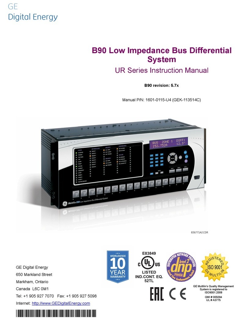
GE Multilin 489 User manual

R
E
G
I
S
T
E
R
E
D
489
GENERATOR MANAGEMENT RELAY®
Instruction Manual
489 Firmware Revision: 32H150A8.000
489PC Software Revision: 1.50
Manual P/N: 1601-0071-E8 (GEK-106290)
Copyright © 2002 GE Power Management
GE Power Management
215 Anderson Avenue, Markham, Ontario
Canada L6E 1B3
Tel: (905) 294-6222 Fax: (905) 294-8512
Internet: http://www.GEindustrial.com/pm Manufactured under an
ISO9001 Registered system.
g
GE Power Managemen
t
808754E3.CDR
489 IN SERVICE BREAKER OPEN R1 TRIP
R2 AUXILIARY
R3 AUXILIARY
R4 AUXILIARY
R5 ALARM
R6 SERVICE
SETPOINT ACCESS BREAKER CLOSED
COMPUTER RS232 HOT STATOR
MESSAGE
VT FAILURE
BREAKER FAILURE
489 Generator Management Relay
PROGRAM PORT SETPOINT 789
456
12 3
.0HELP
MESSAGE
VALUE
ACTUAL
ESCAPE
ENTER
TM
RESET
NEXT
RESET
POSSIBLE
COMPUTER RS485
AUXILIARY RS485
ALT. SETPOINTS
489 STATUS GENERATOR STATUS OUTPUT RELAYS
NEG. SEQUENCE
GROUND
LOSS OF FIELD
g


GE Power Management 489 Generator Management Relay i
TABLE OF CONTENTS
1. INTRODUCTION 1.1 OVERVIEW
1.1.1 DESCRIPTION................................................................................................... 1-1
1.1.2 ORDER INFORMATION.................................................................................... 1-3
1.1.3 OTHER ACCESSORIES....................................................................................1-3
1.2 SPECIFICATIONS
1.2.1 SPECIFICATIONS ............................................................................................. 1-4
2. INSTALLATION 2.1 MECHANICAL
2.1.1 DESCRIPTION................................................................................................... 2-1
2.1.2 PRODUCT IDENTIFICATION............................................................................2-2
2.1.3 INSTALLATION.................................................................................................. 2-3
2.1.4 UNIT WITHDRAWAL AND INSERTION............................................................ 2-3
2.1.5 TERMINAL LOCATIONS ................................................................................... 2-5
2.2 ELECTRICAL
2.2.1 TYPICAL WIRING DIAGRAM............................................................................ 2-7
2.2.2 TYPICAL WIRING.............................................................................................. 2-8
2.2.3 CONTROL POWER...........................................................................................2-9
2.2.4 PHASE CURRENT INPUTS ..............................................................................2-9
2.2.5 GROUND CURRENT INPUT...........................................................................2-10
2.2.6 VOLTAGE INPUTS..........................................................................................2-11
2.2.7 DIGITAL INPUTS............................................................................................. 2-11
2.2.8 ANALOG INPUTS............................................................................................ 2-11
2.2.9 ANALOG OUTPUTS........................................................................................ 2-12
2.2.10 RTD SENSOR CONNECTIONS...................................................................... 2-12
2.2.11 OUTPUT RELAYS ........................................................................................... 2-13
2.2.12 IRIG-B.............................................................................................................. 2-13
2.2.13 RS485 COMMUNICATIONS PORTS .............................................................. 2-14
2.2.14 DIELECTRIC STRENGTH TESTING .............................................................. 2-15
3. OPERATION 3.1 OVERVIEW
3.1.1 489 FACEPLATE ............................................................................................... 3-1
3.1.2 DISPLAY............................................................................................................ 3-2
3.1.3 LED INDICATORS............................................................................................. 3-2
3.1.4 RS232 PROGRAM PORT.................................................................................. 3-3
3.1.5 KEYPAD............................................................................................................. 3-4
3.1.6 ENTERING ALPHANUMERIC TEXT................................................................. 3-4
3.1.7 ENTERING +/– SIGNS ...................................................................................... 3-4
3.2 SETPOINT ENTRY
3.2.1 PROCEDURE .................................................................................................... 3-5
4. SETPOINT PROGRAMMING 4.1 OVERVIEW
4.1.1 TRIPS / ALARMS / CONTROL FEATURES DEFINED .....................................4-1
4.1.2 RELAY ASSIGNMENT PRACTICES................................................................. 4-1
4.1.3 DUAL SETPOINTS ............................................................................................ 4-2
4.1.4 SETPOINT MESSAGE MAP..............................................................................4-2
4.2 S1 489 SETUP
4.2.1 PASSCODE ....................................................................................................... 4-3
4.2.2 PREFERENCES ................................................................................................ 4-3
4.2.3 SERIAL PORTS................................................................................................. 4-4
4.2.4 REAL TIME CLOCK........................................................................................... 4-5
4.2.5 DEFAULT MESSAGES...................................................................................... 4-5
4.2.6 MESSAGE SCRATCHPAD................................................................................ 4-6
4.2.7 CLEAR DATA..................................................................................................... 4-7
4.3 S2 SYSTEM SETUP
4.3.1 CURRENT SENSING ........................................................................................4-8

ii 489 Generator Management Relay GE Power Management
TABLE OF CONTENTS
4.3.2 VOLTAGE SENSING..........................................................................................4-8
4.3.3 GENERATOR PARAMETERS ...........................................................................4-9
4.3.4 SERIAL START/STOP INITIATION....................................................................4-9
4.4 S3 DIGITAL INPUTS
4.4.1 DESCRIPTION .................................................................................................4-10
4.4.2 ACCESS SWITCH............................................................................................4-10
4.4.3 BREAKER STATUS .........................................................................................4-10
4.4.4 GENERAL INPUT A to G..................................................................................4-11
4.4.5 REMOTE RESET .............................................................................................4-12
4.4.6 TEST INPUT.....................................................................................................4-12
4.4.7 THERMAL RESET............................................................................................4-12
4.4.8 DUAL SETPOINTS...........................................................................................4-12
4.4.9 SEQUENTIAL TRIP..........................................................................................4-13
4.4.10 FIELD-BREAKER DISCREPANCY ..................................................................4-14
4.4.11 TACHOMETER.................................................................................................4-14
4.4.12 WAVEFORM CAPTURE .................................................................................4-15
4.4.13 GROUND SWITCH STATUS ...........................................................................4-15
4.5 S4 OUTPUT RELAYS
4.5.1 DESCRIPTION .................................................................................................4-16
4.5.2 RELAY RESET MODE ....................................................................................4-16
4.6 S5 CURRENT ELEMENTS
4.6.1 INVERSE TIME OVERCURRENT CURVE CHARACTERISTICS...................4-17
4.6.2 OVERCURRENT ALARM.................................................................................4-20
4.6.3 OFFLINE OVERCURRENT..............................................................................4-20
4.6.4 INADVERTENT ENERGIZATION.....................................................................4-21
4.6.5 VOLTAGE RESTRAINED PHASE OVERCURRENT.......................................4-22
4.6.6 NEGATIVE SEQUENCE OVERCURRENT......................................................4-23
4.6.7 GROUND OVERCURRENT.............................................................................4-25
4.6.8 PHASE DIFFERENTIAL...................................................................................4-26
4.6.9 GROUND DIRECTIONAL.................................................................................4-27
4.6.10 HIGH-SET PHASE OVERCURRENT...............................................................4-28
4.7 S6 VOLTAGE ELEMENTS
4.7.1 UNDERVOLTAGE............................................................................................4-29
4.7.2 OVERVOLTAGE...............................................................................................4-30
4.7.3 VOLTS/HERTZ.................................................................................................4-31
4.7.4 PHASE REVERSAL .........................................................................................4-32
4.7.5 UNDERFREQUENCY ......................................................................................4-33
4.7.6 OVERFREQUENCY.........................................................................................4-34
4.7.7 NEUTRAL OVERVOLTAGE (FUNDAMENTAL)...............................................4-35
4.7.8 NEUTRAL UNDERVOLTAGE (3RD HARMONIC)...........................................4-36
4.7.9 LOSS OF EXCITATION....................................................................................4-38
4.7.10 DISTANCE ELEMENTS ...................................................................................4-39
4.8 S7 POWER ELEMENTS
4.8.1 POWER MEASUREMENT CONVENTIONS...................................................4-41
4.8.2 REACTIVE POWER .........................................................................................4-42
4.8.3 REVERSE POWER..........................................................................................4-43
4.8.4 LOW FORWARD POWER ...............................................................................4-44
4.9 S8 RTD TEMPERATURE
4.9.1 RTD TYPES......................................................................................................4-45
4.9.2 RTDS 1 TO 6....................................................................................................4-46
4.9.3 RTDS 7 TO 10..................................................................................................4-47
4.9.4 RTD 11 .............................................................................................................4-48
4.9.5 RTD 12 .............................................................................................................4-49
4.9.6 OPEN RTD SENSOR.......................................................................................4-49
4.9.7 RTD SHORT/LOW TEMPERATURE................................................................4-50
4.10 S9 THERMAL MODEL
4.10.1 489 THERMAL MODEL....................................................................................4-51
4.10.2 MODEL SETUP................................................................................................4-52
4.10.3 UNBALANCE BIAS...........................................................................................4-61
4.10.4 MACHINE COOLING........................................................................................4-62
4.10.5 HOT/COLD CURVE RATIO..............................................................................4-63
4.10.6 RTD BIAS .........................................................................................................4-63
4.10.7 THERMAL ELEMENTS ....................................................................................4-64

GE Power Management 489 Generator Management Relay iii
TABLE OF CONTENTS
4.11 S10 MONITORING
4.11.1 TRIP COUNTER .............................................................................................. 4-65
4.11.2 BREAKER FAILURE........................................................................................4-65
4.11.3 TRIP COIL MONITOR...................................................................................... 4-65
4.11.4 VT FUSE FAILURE.......................................................................................... 4-66
4.11.5 CURRENT, MW, MVAR, MVA DEMAND ........................................................4-67
4.11.6 PULSE OUTPUT.............................................................................................. 4-69
4.11.7 GENERATOR RUNNING HOUR SETUP........................................................4-69
4.12 S11 ANALOG I/O
4.12.1 ANALOG OUTPUTS 1 TO 4............................................................................4-70
4.12.2 ANALOG INPUTS 1 TO 4................................................................................ 4-71
4.13 489 TESTING
4.13.1 SIMULATION MODE .......................................................................................4-73
4.13.2 PRE-FAULT SETUP ........................................................................................ 4-74
4.13.3 FAULT SETUP................................................................................................. 4-75
4.13.4 TEST OUTPUT RELAYS................................................................................. 4-75
4.13.5 TEST ANALOG OUTPUT ................................................................................ 4-76
4.13.6 COMM PORT MONITOR................................................................................. 4-76
4.13.7 FACTORY SERVICE ....................................................................................... 4-76
5. ACTUAL VALUES 5.1 OVERVIEW
5.1.1 ACTUAL VALUES MESSAGES......................................................................... 5-1
5.2 A1 STATUS
5.2.1 GENERATOR STATUS ..................................................................................... 5-2
5.2.2 LAST TRIP DATA .............................................................................................. 5-2
5.2.3 ALARM STATUS................................................................................................ 5-3
5.2.4 TRIP PICKUPS.................................................................................................. 5-5
5.2.5 ALARM PICKUPS.............................................................................................. 5-8
5.2.6 DIGITAL INPUTS............................................................................................. 5-11
5.2.7 REAL TIME CLOCK.........................................................................................5-11
5.3 A2 METERING DATA
5.3.1 CURRENT METERING.................................................................................... 5-12
5.3.2 VOLTAGE METERING .................................................................................... 5-13
5.3.3 POWER METERING........................................................................................ 5-14
5.3.4 TEMPERATURE..............................................................................................5-15
5.3.5 DEMAND METERING...................................................................................... 5-16
5.3.6 ANALOG INPUTS............................................................................................ 5-16
5.3.7 SPEED............................................................................................................. 5-16
5.4 A3 LEARNED DATA
5.4.1 PARAMETER AVERAGES.............................................................................. 5-17
5.4.2 RTD MAXIMUMS.............................................................................................5-17
5.4.3 ANALOG IN MIN/MAX .....................................................................................5-18
5.5 A4 MAINTENANCE
5.5.1 TRIP COUNTERS............................................................................................ 5-19
5.5.2 GENERAL COUNTERS................................................................................... 5-21
5.5.3 TIMERS............................................................................................................ 5-21
5.6 A5 EVENT RECORDER
5.6.1 EVENT RECORDER........................................................................................ 5-22
5.7 A6 PRODUCT INFO
5.7.1 489 MODEL INFO ...........................................................................................5-25
5.7.2 CALIBRATION INFO........................................................................................ 5-25
5.8 DIAGNOSTICS
5.8.1 DIAGNOSTIC MESSAGES FOR OPERATORS ............................................. 5-26
5.8.2 FLASH MESSAGES ........................................................................................ 5-27
6. COMMUNICATIONS 6.1 ELECTRICAL INTERFACE
6.1.1 ELECTRICAL INTERFACE................................................................................ 6-1

iv 489 Generator Management Relay GE Power Management
TABLE OF CONTENTS
6.1.2 MODBUS RTU PROTOCOL ..............................................................................6-1
6.1.3 DATA FRAME FORMAT AND DATA RATE.......................................................6-1
6.1.4 DATA PACKET FORMAT...................................................................................6-1
6.1.5 CRC-16 ALGORITHM ........................................................................................6-3
6.1.6 TIMING ...............................................................................................................6-3
6.2 SUPPORTED MODBUS FUNCTIONS
6.2.1 OVERVIEW ........................................................................................................6-4
6.2.2 FUNCTION CODES 03/04: READ SETPOINTS/ACTUAL VALUES..................6-4
6.2.3 FUNCTION CODE 05: EXECUTE OPERATION................................................6-5
6.2.4 FUNCTION CODE 06: STORE SINGLE SETPOINT.........................................6-5
6.2.5 FUNCTION CODE 07: READ DEVICE STATUS ...............................................6-6
6.2.6 FUNCTION CODE 08: LOOPBACK TEST.........................................................6-6
6.2.7 FUNCTION CODE 16: STORE MULTIPLE SETPOINTS...................................6-7
6.2.8 FUNCTION CODE 16: PERFORMING COMMANDS........................................6-8
6.2.9 ERROR RESPONSES .......................................................................................6-8
6.3 MEMORY MAP
6.3.1 MEMORY MAP INFORMATION.........................................................................6-9
6.3.2 USER DEFINABLE MEMORY MAP AREA........................................................6-9
6.3.3 EVENT RECORDER ..........................................................................................6-9
6.3.4 WAVEFORM CAPTURE ..................................................................................6-10
6.3.5 DUAL SETPOINTS...........................................................................................6-10
6.3.6 PASSCODE OPERATION................................................................................6-10
6.3.7 489 MEMORY MAP..........................................................................................6-11
6.3.8 MEMORY MAP DATA FORMATS....................................................................6-40
6.4 DNP COMMUNICATIONS
6.4.1 DEVICE PROFILE DOCUMENT ......................................................................6-45
6.4.2 IMPLEMENTATION TABLE .............................................................................6-47
6.4.3 DEFAULT VARIATIONS...................................................................................6-48
6.5 DNP POINT LISTS
6.5.1 BINARY INPUT / BINARY INPUT CHANGE (OBJECTS 01/02)......................6-49
6.5.2 BINARY / CONTROL RELAY OUTPUT BLOCK (OBJECTS 10/12) ................6-51
6.5.3 BINARY / FROZEN COUNTER (OBJECTS 20/21)..........................................6-52
6.5.4 ANALOG INPUT / INPUT CHANGE (OBJECTS 30/32)...................................6-53
7. TESTING 7.1 TEST SETUP
7.1.1 TEST CONTENTS..............................................................................................7-1
7.1.2 SECONDARY INJECTION TEST SETUP.........................................................7-2
7.2 HARDWARE FUNCTIONAL TESTING
7.2.1 OUTPUT CURRENT ACCURACY ....................................................................7-3
7.2.2 PHASE VOLTAGE INPUT ACCURACY.............................................................7-3
7.2.3 GROUND (1A), NEUTRAL AND DIFFERENTIAL CURRENT ACCURACY ......7-4
7.2.4 NEUTRAL VOLTAGE (FUNDAMENTAL) ACCURACY......................................7-4
7.2.5 NEGATIVE SEQUENCE CURRENT ACCURACY.............................................7-5
7.2.6 RTD ACCURACY ...............................................................................................7-6
7.2.7 DIGITAL INPUTS AND TRIP COIL SUPERVISION...........................................7-7
7.2.8 ANALOG INPUTS AND OUTPUTS....................................................................7-7
7.2.9 OUTPUT RELAYS..............................................................................................7-8
7.3 ADDITIONAL FUNCTIONAL TESTING
7.3.1 OVERLOAD CURVE TEST................................................................................7-9
7.3.2 POWER MEASUREMENT TEST.....................................................................7-10
7.3.3 REACTIVE POWER TEST...............................................................................7-11
7.3.4 VOLTAGE PHASE REVERSAL TEST .............................................................7-12
7.3.5 INJECTION TEST SETUP #2...........................................................................7-12
7.3.6 GE POWER MANAGEMENT HGF GROUND ACCURACY TEST ..................7-13
7.3.7 NEUTRAL VOLTAGE (3RD HARMONIC) ACCURACY TEST.........................7-13
7.3.8 PHASE DIFFERENTIAL TRIP TEST................................................................7-14
7.3.9 INJECTION TEST SETUP #3...........................................................................7-15
7.3.10 VOLTAGE RESTRAINED OVERCURRENT TEST..........................................7-16

GE Power Management 489 Generator Management Relay v
TABLE OF CONTENTS
8. 489PC SOFTWARE 8.1 INSTALLATION/UPGRADE
8.1.1 DESCRIPTION................................................................................................... 8-1
8.1.2 HARDWARE & SOFTWARE REQUIRMENTS..................................................8-1
8.1.3 CHECKING IF INSTALLATION/UPGRADE IS REQUIRED .............................. 8-2
8.1.4 INSTALLING/UPGRADING 489PC ...................................................................8-3
8.2 CONFIGURATION
8.2.1 STARTUP & COMMUNICATIONS CONFIGURATION ..................................... 8-4
8.3 USING 489PC
8.3.1 SAVING SETPOINTS TO A FILE ...................................................................... 8-5
8.3.2 UPGRADING THE 489 FIRMWARE.................................................................. 8-6
8.3.3 LOADING SETPOINTS FROM A FILE.............................................................. 8-7
8.3.4 ENTERING SETPOINTS ................................................................................... 8-7
8.3.5 UPGRADING SETPOINT FILES TO NEW REVISION...................................... 8-9
8.3.6 PRINTING SETPOINTS & ACTUAL VALUES...................................................8-9
8.3.7 TRENDING ...................................................................................................... 8-10
8.3.8 WAVEFORM CAPTURE.................................................................................. 8-12
8.3.9 PHASORS........................................................................................................8-13
8.3.10 EVENT RECORDER........................................................................................ 8-14
8.3.11 TROUBLESHOOTING..................................................................................... 8-15
A. COMMISSIONING A.1 COMMISSIONING
A.1.1 SETPOINTS SUMMARY ...................................................................................A-1
B. APPLICATION NOTES B.1 STATOR GROUND FAULT PROTECTION
B.1.1 DESCRIPTION...................................................................................................B-1
B.1.2 NEUTRAL OVERVOLTAGE ELEMENT ............................................................B-1
B.1.3 GROUND OVERCURRENT ELEMENT ............................................................B-3
B.1.4 GROUND DIRECTIONAL ELEMENT................................................................B-4
B.1.5 THIRD HARMONIC VOLTAGE ELEMENT........................................................B-6
B.1.6 REFERENCES...................................................................................................B-6
C. CURVES C.1 TIME OVERCURRENT CURVES
C.1.1 ANSI CURVES...................................................................................................C-1
C.1.2 DEFINITE TIME CURVE....................................................................................C-5
C.1.3 IAC CURVES .....................................................................................................C-6
C.1.4 IEC CURVES ...................................................................................................C-10
D. CTs D.1 CURRENT TRANSFORMERS
D.1.1 GROUND FAULT CTs FOR 50:0.025 A CT ......................................................D-1
D.1.2 GROUND FAULT CTs FOR 5 A SECONDARY CT...........................................D-2
D.1.3 PHASE CTS.......................................................................................................D-3
E. WARRANTY E.1 WARRANTY INFORMATION
E.1.1 WARRANTY.......................................................................................................E-1
F. APPENDIX F F.1 FIGURES AND TABLES
F.1.1 LIST OF FIGURES.............................................................................................F-1
F.1.2 LIST OF TABLES...............................................................................................F-2

vi 489 Generator Management Relay GE Power Management
TABLE OF CONTENTS

GE Power Management 489 Generator Management Relay 1-1
1 INTRODUCTION 1.1 OVERVIEW
1
1 INTRODUCTION 1.1 OVERVIEW 1.1.1 DESCRIPTION
The 489 Generator Management Relay is a microprocessor-based relay designed for the protection and management of
synchronous and induction generators. The 489 is equipped with 6 output relays for trips and alarms. Generator protection,
fault diagnostics, power metering, and RTU functions are integrated into one economical drawout package. The single line
diagram below illustrates the 489 functionality using ANSI (American National Standards Institute) device numbers.
Figure 1–1: SINGLE LINE DIAGRAM
Fault diagnostics are provided through pretrip data, event record, waveform capture, and statistics. Prior to issuing a trip,
the 489 takes a snapshot of the measured parameters and stores them in a record with the cause of the trip. This pre-trip
data may be viewed using the key before the trip is reset, or by accessing the last trip data in actual values page 1.
The event recorder stores a maximum of 40 time and date stamped events including the pre-trip data. Every time a trip
occurs, the 489 stores a 16 cycle trace for all measured AC quantities. Trip counters record the number of occurrences of
each type of trip. Minimum and maximum values for RTDs and analog inputs are also recorded. These features allow the
operator to pinpoint a problem quickly and with certainty.
A complete list protection features may be found below in the table below:
808783E6.CDR
87G
27TN59GN
49
50
46
86
49
12
38
50BF
Output
relays
Trip Coil
Supervision
RS485
RS485
Analog
inputs
Analog
outputs
Output
relays
489
RS232
+
+
-
-
4
4
6
52
GENERATOR
41
39
76
50/51GN
60FL
51V
50/27
32
21
40
40Q
24
59
810
81U
27
47
67
12 overspeed
volts/hertz
undervoltage
inadvertent generator energization
reverse power/low forward power
bearing overtemperature (RTD)
bearing vibration (analog inputs)
loss of field (reactive power)
negative sequence overcurrent (I t)
2
2
voltage phase reversal
stator thermal (RTD/thermal model)
breaker failure detection
offline overcurrent
ground overcurrent
voltage restrained phase overcurrent
overvoltage
100% stator ground
VT fuse failure
overexcitation (analog input)
overfrequency/underfrequency
percentage differential
electrical lockout
ground directional
high-set phase overcurrent
loss of excitation (impedance)
distance
sequential tripping logic
trip coil supervision
24
27
50/27
32
38
39
40Q
46
47
49
50BF
50
50/51GN
51V
59
59GN/27TN
60FL
76
81
87G
86
67
50
40
21
Synchronous
Induction
generator running hours alarm
NEXT

1-2 489 Generator Management Relay GE Power Management
1.1 OVERVIEW 1 INTRODUCTION
1
Power metering is a standard feature in the 489. The table below outlines the metered parameters available to the operator
or plant engineer either through the front panel or communications ports. The 489 is equipped with three fully functional and
independent communications ports. The front panel RS232 port may be used for setpoint programming, local interrogation
or control, and firmware upgrades. The computer RS485 port may be connected to a PLC, DCS, or PC based interface
software. The auxiliary RS485 port may be used for redundancy or simultaneous interrogation and/or control from a second
PLC, DCS, or PC program. There are also four 4 to 20 mA transducer outputs that may be assigned to any measured
parameter. The range of these outputs is scalable. Additional features are outlined below.
Table 1–1: TRIP AND ALARM PROTECTION FEATURES
TRIP PROTECTION ALARM PROTECTION
7 assignable digital inputs:
general input, sequential trip (low forward power or reverse
power), field-breaker discrepancy, and tachometer
7 assignable digital inputs: general input and tachometer
overload
negative sequence
offline overcurrent (protection during startup) ground overcurrent
inadvertent energization ground directional
phase overcurrent with voltage restraint undervoltage
negative sequence overcurrent overvoltage
ground overcurrent volts/hertz
percentage phase differential underfrequency
ground directional overfrequency
high-set phase overcurrent neutral overvoltage (fundamental)
undervoltage neutral undervoltage (3rd harmonic)
overvoltage reactive power (kvar)
volts/hertz reverse power
voltage phase reversal low forward power
underfrequency (two step) RTD: stator, bearing, ambient, other
overfrequency (two step) short/low RTD
neutral overvoltage (fundamental) open RTD
neutral undervoltage (3rd harmonic) thermal overload
loss of excitation (2 impedance circles) trip counter
distance element (2 zones of protection) breaker failure
reactive power (kvar) for loss of field trip coil monitor
reverse power for anti-motoring VT fuse failure
low forward power demand: current, MW, Mvar, MVA
RTDs: stator, bearing, ambient, other generator running hours
thermal overload analog inputs 1 to 4
analog inputs 1 to 4 service (self-test failures)
electrical lockout IRIG-B failure
Table 1–2: METERING AND ADDITIONAL FEATURES
METERING ADDITIONAL FEATURES
voltage (phasors)
current (phasors) and amps demand
real power, MW demand, MWh
apparent power and MVA demand
reactive power, Mvar demand, Mvarh positive/negative
frequency
power factor
RTD
speed in RPM with a key phasor Input
user programmable analog inputs
drawout case
(for ease of maintenance and testing)
breaker failure
trip coil supervision
VT fuse failure
simulation
flash memory for easy firmware updates

GE Power Management 489 Generator Management Relay 1-3
1 INTRODUCTION 1.1 OVERVIEW
1
1.1.2 ORDER INFORMATION
All features of the 489 are standard, there are no options. The phase CT secondaries must be specified at the time of order.
The control power and analog output range must also be specified at the time of order. There are two ground CT inputs:
one for the GE Power Management HGF core balance CT and one for a ground CT with a 1 A secondary (may also be
used to accommodate 5 A secondary). The VT inputs accommodate VTs in either a delta or wye configuration. The output
relays are always non-failsafe with the exception of the service relay. The 489PC software is provided with each unit. A
metal demo case may be ordered for demonstration or testing purposes.
Figure 1–2: 489 ORDER CODES
1.1.3 OTHER ACCESSORIES
Additional 489 accessories are listed below.
•489PC software: Shipped free with 489
•DEMO: Metal carry case in which 489 unit may be mounted
•SR 19-1 PANEL: Single cutout for 19” panel
•SR 19-2 PANEL: Double cutout for 19” panel
•SCI MODULE: RS232 to RS485 converter box, designed for harsh industrial environments
•Phase CT: 50, 75, 100, 150, 200, 250, 300, 350, 400, 500, 600, 750, 1000 phase CT primaries
•HGF3, HGF5, HGF8: For sensitive ground detection on high resistance grounded systems
•489 1 3/8” Collar: For shallow switchgear, reduces the depth of the relay by 1 3/8”
•489 3” Collar: For shallow switchgear, reduces the depth of the relay by 3”
489
489 Basic unit
P1
P5
Current Transformer Inputs:1ACTSecondaries
Current Transformer Inputs:5ACTSecondaries
LO
HI
DC: 25-60 V; AC: 20-48 V @ 48-62 Hz
DC: 90-300 V; AC: 70-265 V @ 48-62 Hz
A1
A20
0-1 mA analog outputs
4-20 mA analog outputs
***

1-4 489 Generator Management Relay GE Power Management
1.2 SPECIFICATIONS 1 INTRODUCTION
11.2 SPECIFICATIONS 1.2.1 SPECIFICATIONS
POWER SUPPLY
Options: LO / HI
(must be specified when orderin
g
)
LO Ran
g
e: DC: 20 to 60 V DC
AC: 20 to 48 V AC at 48 to 62 Hz
HI Ran
g
e: DC: 90 to 300 V DC
AC: 70 to 265 V AC at 48 to 62 Hz
Power: 45 VA (max), 25 VA typical
Proper operation time without supply volta
g
e: 30 ms
AC ANALOG INPUTS FREQUENCY TRACKING
Frequency Trackin
g
: Va for wye, Vab for open delta
6 V minimum, 10 Hz/sec.
OUTPUT AND NEUTRAL END CURRENT INPUTS
CT Primary: 10 to 50000 A
CT Secondary: 1 A or 5 A (must be specified with order)
Conversion Ran
g
e: 0.02 to 20 ×CT
Accuracy: at <2 ×CT: ±0.5% of 2 ×CT
at ≥ 2 ×CT: ±1% of 20 ×CT
Burden: Less than 0.2 VA at rated load
CT Withstand: 1 second at 80 times rated current
2 seconds at 40 times rated current
continuous at 3 times rated current
GROUND CURRENT INPUT
CT Primary: 10 to 10000 A (1 A / 5 A CTs)
CT Secondary: 1 A / 5 A or 50:0.025 (HGF CTs)
Conversion Ran
g
e: 0.02 to 20 ×CT for 1 A / 5 A CTs
0.0 to 100 A pri. for 50:0.025 CTs (HGF)
50:0.025 CT Accuracy: ± 0.1 A at <10 A
± 1.0 A at ≥10 to 100 A
1 A / 5 A CT Accuracy: at <2 ×CT: ±0.5% of 2 ×CT
at ≥2 ×CT: ±1% of 20 ×CT
GROUND CT BURDEN
GROUND CT CURRENT WITHSTAND (SECONDARY)
PHASE VOLTAGE INPUTS
VT Ratio: 1.00 to 240.00:1 in steps of 0.01
VT Secondary: 200 VAC (full-scale)
Conversion Ran
g
e: 0.02 to 1.00 ×Full Scale
Accuracy: ±0.5% of Full Scale
Max. Continuous: 280 V AC
Burden: >500 KΩ
NEUTRAL VOLTAGE INPUT
VT Ratio: 1.00 to 240.00:1 in steps of 0.01
VT Secondary: 100 VAC (full-scale)
Conversion Ran
g
e: 0.005 to 1.00 ×Full Scale
Accuracy: ±0.5% of Full Scale
Max. Continuous: 280 V AC
DIGITAL INPUTS
Inputs: 9 opto-isolated inputs
External Switch: dry contact <400 Ω, or open collector
NPN transistor from sensor
6 mA sinkin
g
from internal 4K pullup at
24 V DC with Vce <4 V DC
489 Sensor Supply: 24 V DC at 20 mA max.
RTD INPUTS
RTDs (3 wire type): 100 ΩPlatinum (DIN.43760)
100 ΩNickel, 120 ΩNickel,
10 ΩCopper
RTD Sensin
g
Current: 5 mA
Isolation: 36 Vpk
(isolated with analo
g
inputs and outputs)
Ran
g
e: –50 to +250°C
Accuracy: ±2°C for Platinum and Nickel
±5°C for Copper
Lead Resistance: 25 ΩMax per lead
No Sensor: >1 kΩ
Short/Low Alarm: <–50°C
TRIP COIL SUPERVISION
Applicable Volta
g
e: 20 to 300 V DC/AC
Trickle Current: 2 to 5 mA
ANALOG CURRENT INPUTS
Current Inputs: 0 to 1 mA, 0 to 20 mA, 4 to 20mA
(setpoint)
Input Impedance: 226 Ω±10%
Conversion Ran
g
e: 0 to 2 mA
Accuracy: ±1% of full scale
Type: Passive
Analo
g
Input Supply: +24 V DC at 100 mA max.
Samplin
g
Interval: 50 ms
COMMUNICATIONS PORTS
RS232 Port: 1, Front Panel, non-isolated
RS485 Ports: 2, Isolated to
g
ether at 36 Vpk
RS485 Baud Rates: 300, 1200, 2400, 4800, 9600, 19200
RS232 Baud Rate: 9600
Parity: None, Odd, Even
Protocol: Modbus®RTU / half duplex, DNP 3.0
GROUND
CT INPUT BURDEN
VA Ω
1 A / 5 A 1 A 0.024 0.024
5 A 0.605 0.024
20 A 9.809 0.024
50:0.025
HGF 0.025 A 0.057 90.7
0.1 A 0.634 90.7
0.5 A 18.9 75.6
GROUND CT WITHSTAND TIME
1 SEC. 2 SEC. CONTINUOUS
1A/5A 80×CT 40 ×CT 3 ×CT
50:0.025 HGF N/A N/A 150 mA

GE Power Management 489 Generator Management Relay 1-5
1 INTRODUCTION 1.2 SPECIFICATIONS
1
ANALOG CURRENT OUTPUT
Type: Active
Ran
g
e: 4 to 20mA, 0 to 1 mA
(must be specified with order)
Accuracy: ±1% of full scale
4 to 20 mA max. load: 1.2 kΩ
0 to 1mA max. load: 10 kΩ
Isolation: 36 Vpk
(isolated with RTDs and analo
g
inputs)
4 Assi
g
nable Outputs: Phase A, B, C output current
3 phase avera
g
e current
ne
g
ative sequence current
g
enerator load
hottest stator RTD
hottest bearin
g
RTD
RTD # 1 to 12
AB volta
g
e
BC volta
g
e
CA volta
g
e
avera
g
e phase-phase volta
g
e
volts/hertz
frequency
3rd harmonic neutral volta
g
e
power factor
3 phase reactive power (Mvar)
3 phase real power (MW)
3 phase apparent power (MVA)
analo
g
inputs 1 to 4
tachometer
thermal capacity used
I, Mvar, MW, MVA demands
Torque
OUTPUT RELAYS
Confi
g
uration: 6 electromechanical Form C relays
Contact Material: silver alloy
Operate Time: 10 ms
Max Ratin
g
s for 100000 operations:
TERMINALS
Low Volta
g
e (A, B, C, D terminals): 12 AWG max
Hi
g
h Volta
g
e (E, F, G, H terminals): #8 rin
g
lu
g
,
10 AWG wire standard
POWER METERING
Ran
g
e: 0.000 to 2000.000 ±Mw, ±Mvar, MVA
Accuracy
at Iav
g
<2 ×CT: ±1% of ×2×CT ×VT ×VT full-scale
at Iav
g
>2 × CT: ±1.5% of ×20 ×CT ×VT ×VT full-scl.
WATTHOUR AND VARHOUR METERING
Description: Continuous total of +watthours and
±varhours
Ran
g
e: 0.000 to 4000000.000 MvarHours
Timin
g
Accuracy: ±0.5%
Update Rate: 50 ms
DEMAND METERING
Metered Values: Maximum Phase Current
3 Phase Real Power
3 Phase Apparent Power
3 Phase Reactive Power
Measurement Type: Rollin
g
Demand
Demand Interval: 5 to 90 minutes in steps of 1
Update Rate: 1 minute
Elements: Alarm
GENERAL INPUT A TO G (DIGITAL INPUT)
Confi
g
urable: Assi
g
nable Di
g
ital Inputs 1 to 7
Time Delay: 0.1 to 5000.0 s in steps of 0.1
Block From Online: 0 to 5000 s in steps of 1
Timin
g
Accuracy: ±100 ms or ±0.5% of total time
Elements: Trip, Alarm, and Control
SEQUENTIAL TRIP (DIGITAL INPUT)
Confi
g
urable: Assi
g
nable to Di
g
ital Inputs 1 to 7
Pickup Level: 0.02 to 0.99 ×rated MW in steps of 0.01
Low Forward Power / Reverse Power
Time Delay: 0.2 to 120.0 s in steps of 0.1
Pickup Accuracy: see power meterin
g
Timin
g
Accuracy: ±100 ms or ±0.5% of total time
Elements: Trip
FIELD BREAKER DISCREPANCY (DIGITAL INPUT)
Confi
g
urable: Assi
g
nable to Di
g
ital Inputs 1 to 7
Time Delay: 0.1 to 500.0 s in steps of 0.1
Timin
g
Accuracy: ±100 ms or ±0.5% of total time
Elements: Trip
TACHOMETER (DIGITAL INPUT)
Confi
g
urable: Assi
g
nable to Di
g
ital Inputs 4 to 7
RPM Measurement: 100 to 7200 RPM
Duty Cycle of Pulse: >10%
Pickup Level: 101 to 175 ×rated speed in steps of 1
Time Delay: 1 to 250 s in steps of 1
Timin
g
Accuracy: ±0.5 s or ±0.5% of total time
Elements: Trip and Alarm
OVERCURRENT ALARM
Pick-up Level: 0.10 to 1.50 ×FLA in steps of 0.01
avera
g
e phase current
Time Delay: 0.1 to 250.0 s in steps of 0.1
Pickup Accuracy: as per Phase Current Inputs
Timin
g
Accuracy: ±100 ms or ±0.5% of total time
Elements: Alarm
VOLTAGE MAKE/CARRY BREAK MAX.
LOAD
CTS 0.2 s
DC
RESISTIVE 30 V 10 A 30 A 10 A 300 W
125 V 10 A 30 A 0.5 A 62.5 W
250 V 10 A 30 A 0.3 A 75 W
DC
INDUCTIVE
L/R = 40 ms
30 V 10 A 30 A 5 A 150 W
125 V 10 A 30 A 0.25 A 31.3 W
250 V 10 A 30 A 0.15 A 37.5 W
AC
RESISTIVE 120 V 10 A 30 A 10 A 2770 VA
250 V 10 A 30 A 10 A 2770 VA
AC
INDUCTIVE
PF = 0.4
120 V 10 A 30 A 4 A 480 VA
250 V 10 A 30 A 3 A 750 VA
33

1-6 489 Generator Management Relay GE Power Management
1.2 SPECIFICATIONS 1 INTRODUCTION
1OFFLINE OVERCURRENT
Pick-up Level: 0.05 to 1.00 ×CT in steps of 0.01
of any one phase
Time Delay: 3 to 99 cycles in steps of 1
Pickup Accuracy: as per Phase Current Inputs
Timin
g
Accuracy: +50ms at 50/60 Hz
Elements: Trip
INADVERTENT ENERGIZATION
Armin
g
Si
g
nal: undervolta
g
e and/or offline from breaker
status
Pick-up Level: 0.05 to 3.00 ×CT in steps of 0.01
of any one phase
Time Delay: no intentional delay
Pickup Accuracy: as per Phase Current Inputs
Timin
g
Accuracy: +50 ms at 50/60 Hz
Elements: Trip
PHASE OVERCURRENT
Volta
g
e Restraint: Pro
g
rammable fixed characteristic
Pick-up Level: 0.15 to 20.00 ×CT in steps of 0.01
of any one phase
Curve Shapes: ANSI, IEC, IAC, Flexcurve, Definite Time
Time Delay: 0.000 to 100.000 s in steps of 0.001
Pickup Accuracy: as per Phase Current Inputs
Timin
g
Accuracy: +50 ms at 50/60 Hz or ±0.5% total time
Elements: Trip
NEGATIVE SEQUENCE OVERCURRENT
Pick-up Level: 3 to 100% FLA in steps of 1
Curve Shapes: I22t trip defined by k, definite time alarm
Time Delay: 0.1 to 100.0 s in steps of 0.1
Pickup Accuracy: as per Phase Current Inputs
Timin
g
Accuracy: ±100ms or ± 0.5% of total time
Elements: Trip and Alarm
GROUND OVERCURRENT
Pick-up Level: 0.05 to 20.00 ×CT in steps of 0.01
Curve Shapes: ANSI, IEC, IAC, Flexcurve, Definite Time
Time Delay: 0.00 to 100.00 s in steps of 0.01
Pickup Accuracy: as per Ground Current Input
Timin
g
Accuracy: +50 ms at 50/60 Hz or ±0.5% total time
Elements: Trip
PHASE DIFFERENTIAL
Pick-up Level: 0.05 to 1.00 ×CT in steps of 0.01
Curve Shape: Dual Slope
Time Delay: 0 to 100 cycles in steps of 1
Pickup Accuracy: as per Phase Current Inputs
Timin
g
Accuracy: +50 ms at 50/60 Hz or ±0.5% total time
Elements: Trip
GROUND DIRECTIONAL
Pickup Level: 0.05 to 20.00 ×CT in steps of 0.01
Time Delay: 0.1 to 120.0 s in steps of 0.1
Pickup Accuracy: as per Phase Current Inputs
Timin
g
Accuracy: ±100 ms or ±0.5% of total time
Elements: Trip and Alarm
HIGH-SET PHASE OVERCURRENT
Pickup Level: 0.15 to 20.00 ×CT in steps of 0.01
Time Delay: 0.00 to 100.00 s in steps of 0.01
Pickup Accuracy: as per Phase Current Inputs
Timin
g
Accuracy: ±50 ms at 50/60 Hz or ±0.5% total time
Elements: Trip
UNDERVOLTAGE
Pick-up Level: 0.50 to 0.99 ×rated V in steps of 0.01
Curve Shapes: Inverse Time, definite time alarm
Time Delay: 0.2 to 120.0 s in steps of 0.1
Pickup Accuracy: as per Volta
g
e Inputs
Timin
g
Accuracy: ±100 ms or ±0.5% of total time
Elements: Trip and Alarm
OVERVOLTAGE
Pick-up Level: 1.01 to 1.50 ×rated V in steps of 0.01
Curve Shapes: Inverse Time, definite time alarm
Time Delay: 0.2 to 120.0 s in steps of 0.1
Pickup Accuracy: as per Volta
g
e Inputs
Timin
g
Accuracy: ±100 ms or ±0.5% of total time
Elements: Trip and Alarm
VOLTS/HERTZ
Pick-up Level: 1.00 to 1.99 ×nominal in steps of 0.01
Curve Shapes: Inverse Time, definite time alarm
Time Delay: 0.1 to 120.0 s in steps of 0.1
Pickup Accuracy: as per volta
g
e inputs
Timin
g
Accuracy: ±100 ms at ≥ 1.2 ×Pickup
±300 ms at < 1.2 ×Pickup
Elements: Trip and Alarm
VOLTAGE PHASE REVERSAL
Confi
g
uration: ABC or ACB phase rotation
Timin
g
Accuracy: 200 to 400 ms
Elements: Trip
UNDERFREQUENCY
Required Volta
g
e: 0.50 to 0.99 ×rated volta
g
e in Phase A
Block From Online: 0 to 5 sec. in steps of 1
Pick- up Level: 20.00 to 60.00 in steps of 0.01
Curve Shapes: 1 level alarm, two level trip definite time
Time Delay: 0.1 to 5000.0 sec. in steps of 0.1
Pickup Accuracy: ±0.02 Hz
Timin
g
Accuracy: ±100 ms or ±0.5% of total time
Elements: Trip and Alarm
OVERFREQUENCY
Required Volta
g
e: 0.50 to 0.99 ×rated volta
g
e in Phase A
Block From Online: 0 to 5 sec. in steps of 1
Pick- up Level: 25.01 to 70.00 in steps of 0.01
Curve Shapes: 1 level alarm, 2 level trip definite time
Time Delay: 0.1 to 5000.0 s in steps of 0.1
Pickup Accuracy: ±0.02 Hz
Timin
g
Accuracy: ±100 ms or ±0.5% of total time
Elements: Trip and Alarm

GE Power Management 489 Generator Management Relay 1-7
1 INTRODUCTION 1.2 SPECIFICATIONS
1
NEUTRAL OVERVOLTAGE (FUNDAMENTAL)
Pick-up Level: 2.0 to 100.0 V secondary in steps of 0.01
Time Delay: 0.1 to 120.0 s in steps of 0.1
Pickup Accuracy: as per Neutral Volta
g
e Input
Timin
g
Accuracy: ±100 ms or ±0.5% of total time
Elements: Trip and Alarm
NEUTRAL UNDERVOLTAGE (3RD HARMONIC)
Blockin
g
Si
g
nals: Low power and low volta
g
e if open delta
Pick-up Level: 0.5 to 20.0 V secondary in steps of 0.01
if open delta VT; adaptive if wye VT
Time Delay: 5 to 120 s in steps of 1
Pickup Accuracy:
at ≤20.0 V secondary: as per Neutral Volta
g
e Input
at >20.0 V secondary: ±5% of pickup
Timin
g
Accuracy: ±3.0 s
Elements: Trip and Alarm
LOSS OF EXCITATION (IMPEDANCE)
Pickup Level: 2.5 to 300.0 Ωsecondary in steps of 0.1
with adjustable impedance offset 1.0 to
300.0 Ωsecondary in steps of 0.1
Time Delay: 0.1 to 10.0 s in steps of 0.1
Pickup Accuracy: as per Volta
g
e and Phase Current Inputs
Timin
g
Accuracy: ±100 ms or ±0.5% of total time
Elements: Trip (2 zones usin
g
impedance circles)
DISTANCE (IMPEDANCE)
Pickup Levels: 0.1 to 500.0 Ωsecondary in steps of 0.1
50 to 85° reach in steps of 1
Time Delay: 0.0 to 150.0 s in steps of 0.1
Pickup Accuracy: as per Volta
g
e and Phase Current Inputs
Timin
g
Accuracy: 150 ms ±50 ms or ±0.5% of total time
Elements: Trip (two trip zones)
REACTIVE POWER
Block From Online: 0 to 5000 s in steps of 1
Pick- up Level: 0.02 to 1.50 ×rated Mvar
(positive and ne
g
ative)
Time Delay: 0.2 to 120.0 s in steps of 0.1
Pickup Accuracy: see power meterin
g
Timin
g
Accuracy: ±100ms or ±0.5% of total time
Elements: Trip and Alarm
REVERSE POWER
Block From Online: 0 to 5000 s in steps of 1
Pick- up Level: 0.02 to 0.99 ×rated MW
Time Delay: 0.2 to 120.0 s in steps of 0.1
Pickup Accuracy: see power meterin
g
Timin
g
Accuracy: ±100 ms or ±0.5% of total time
Elements: Trip and Alarm
LOW FORWARD POWER
Block From Online: 0 to 15000 s in steps of 1
Pick- up Level: 0.02 to 0.99 ×rated MW
Time Delay: 0.2 to 120.0 s in steps of 0.1
Pickup Accuracy: see power meterin
g
Timin
g
Accuracy: ±100 ms or ±0.5% of total time
Elements: Trip and Alarm
PULSE OUTPUT
Parameters: + kwh, +kvarh, -kvarh
Interval: 1 to 50000 in steps of 1
Pulse Width: 200 to 1000 ms in steps of 1 ms
RTDS 1 TO 12
Pickup: 1 to 250°C in steps of 1
Pickup Hysteresis: 2°C
Time Delay: 3 sec.
Elements: Trip and Alarm
OVERLOAD / STALL PROTECTION / THERMAL MODEL
Overload Curves: 15 Standard Overload Curves
Custom Curve
Volta
g
e Dependent Custom Curve
(all curves time out a
g
ainst avera
g
e
phase current)
Curve Biasin
g
: Phase Unbalance
Hot/Cold Curve Ratio
Stator RTD
Online Coolin
g
Rate
Offline Coolin
g
Rate
Line Volta
g
e
Overload Pickup: 1.01 to 1.25
Pickup Accuracy: as per Phase Current Inputs
Timin
g
Accuracy: ±100 ms or ±2% of total time
Elements: Trip and Alarm
OTHER FEATURES
Serial Start/Stop Initiation
Remote Reset (Confi
g
urable Di
g
ital Input)
Test Input (Confi
g
urable Di
g
ital Input)
Thermal Reset (Confi
g
urable Di
g
ital Input)
Dual Setpoints
Pre-Trip Data
Event Recorder
Waveform Memory
Fault Simulation
VT Failure
Trip Counter
Breaker Failure
Trip Coil Monitor
Generator Runnin
g
Hours Alarm
IRIG-B Failure Alarm
ENVIRONMENTAL
Ambient Operatin
g
Temperature: –40°C to +60°C
Ambient Stora
g
e Temperature: 40°C to +80°C.
Humidity: Up to 90%, noncondensin
g
.
Altitude: Up to 2000 m
Pollution De
g
ree: 2
It is recommended that the 489 be powered up
at least once per year to prevent deterioration
of electrolytic capacitors in the power supply.
WARNING

1-8 489 Generator Management Relay GE Power Management
1.2 SPECIFICATIONS 1 INTRODUCTION
1CASE
Drawout: Fully drawout (Automatic CT shorts)
Seal: Seal provision
Door: Dust ti
g
ht door
Mountin
g
: Panel or 19" rack mount
IP Class: IP20-X
PRODUCTION TESTS
Thermal Cyclin
g
: Operational test at ambient, reducin
g
to
–40°C and then increasin
g
to 60°C
Dielectric Stren
g
th: 2.0 kV for 1 minute from relays, CTs,
VTs, power supply to Safety Ground
DO NOT CONNECT FILTER GROUND TO
SAFETY GROUND DURING TEST!
FUSE
Current Ratin
g
:3.15A
Type: 5 ×20 mm Slo-Blo Littelfuse, Hi
g
h
Breakin
g
Capacity
Model#: 215.315
An external fuse must be used if supply voltage
exceeds 250V
TYPE TESTS
Dielectric Stren
g
th: Per IEC 255-5 and ANSI/IEEE C37.90.
2.0 kV for 1 minute from relays, CTs,
VTs, power supply to Safety Ground
DO NOT CONNECT FILTER GROUND TO SAFETY
GROUND DURING TEST
Insulation Resistance: IEC255-5 500 V DC, from relays, CTs,
VTs, power supply to Safety Ground
DO NOT CONNECT FILTER GROUND TO
SAFETY GROUND DURING TEST
Transients: ANSI C37.90.1 oscillatory (2.5 kV/
1 MHz); ANSI C37.90.1 Fast Rise (5 kV/
10 ns); Ontario Hydro A-28M-82;
IEC255-4 Impulse/Hi
g
h Frequency Dis-
turbance Class III Level
Impulse Test: IEC 255-5 0.5 Joule 5 kV
RFI: 50 MHz / 15 W Transmitter
EMI: C37.90.2 Electroma
g
netic Interference
at 150 MHz and 450 MHz, 10V/m
Static: IEC 801-2 Static Dischar
g
e
Humidity: 90% non-condensin
g
Temperature: –40°C to +60°C ambient
Environment: IEC 68-2-38 Temperature/Humidity cycle
Vibration: Sinusoidal Vibration 8.0
g
for 72 hrs.
PACKAGING
Shippin
g
Box: 12” ×11” ×10” (W ×H ×D)
30.5cm ×27.9cm ×25.4cm
Shippin
g
Wei
g
ht: 17 lbs Max / 7.7 k
g
CERTIFICATION
ISO: Manufactured under an ISO9001 re
g
is-
tered system.
UL: UL
CSA: CSA
CE: Conforms to IEC 947-1, IEC 1010-1
WARNING
WARNING
WARNING
WARNING

GE Power Management 489 Generator Management Relay 2-1
2 INSTALLATION 2.1 MECHANICAL
2
2 INSTALLATION 2.1 MECHANICAL 2.1.1 DESCRIPTION
The 489 is packaged in the standard GE Power Management SR series arrangement, which consists of a drawout unit and
a companion fixed case. The case provides mechanical protection to the unit, and is used to make permanent connections
to all external equipment. The only electrical components mounted in the case are those required to connect the unit to the
external wiring. Connections in the case are fitted with mechanisms required to allow the safe removal of the relay unit from
an energized panel, such as automatic CT shorting. The unit is mechanically held in the case by pins on the locking handle,
which cannot be fully lowered to the locked position until the electrical connections are completely mated. Any 489 can be
installed in any 489 case, except for custom manufactured units that are clearly identified as such on both case and unit,
and are equipped with an index pin keying mechanism to prevent incorrect pairings.
No special ventilation requirements need to be observed during the installation of the unit, but the unit should be wiped
clean with a damp cloth.
Figure 2–1: 489 DIMENSIONS
To prevent unauthorized removal of the drawout unit, a wire lead seal can be installed in the slot provided on the handle as
shown below. With this seal in place, the drawout unit cannot be removed. A passcode or setpoint access jumper can be
used to prevent entry of setpoints but still allow monitoring of actual values. If access to the front panel controls must be
restricted, a separate seal can be installed on the outside of the cover to prevent it from being opened.
Figure 2–2: DRAWOUT UNIT SEAL
Hazard may result if the product is not used for its intended purpose.
WARNING

2-2 489 Generator Management Relay GE Power Management
2.1 MECHANICAL 2 INSTALLATION
2
2.1.2 PRODUCT IDENTIFICATION
Each 489 unit and case are equipped with a permanent label. This label is installed on the left side (when facing the front of
the relay) of both unit and case. The case label details which units can be installed.
The case label details the following information:
• MODEL NUMBER
• MANUFACTURE DATE
• SPECIAL NOTES
The unit label details the following information:
• MODEL NUMBER
•TYPE
• SERIAL NUMBER
• FILE NUMBER
• MANUFACTURE DATE
• PHASE CURRENT INPUTS
• SPECIAL NOTES
• OVERVOLTAGE CATEGORY
• INSULATION VOLTAGE
• POLLUTION DEGREE
• CONTROL POWER
• OUTPUT CONTACT RATING
Figure 2–3: CASE AND UNIT IDENTIFICATION LABELS

GE Power Management 489 Generator Management Relay 2-3
2 INSTALLATION 2.1 MECHANICAL
2
2.1.3 INSTALLATION
The 489 case, alone or adjacent to another SR unit, can be installed in a standard 19-inch rack panel (see Figure 2–1: 489
DIMENSIONS on page 2–1). Provision must be made for the front door to swing open without interference to, or from, adja-
cent equipment. The 489 unit is normally mounted in its case when shipped from the factory and should be removed before
mounting the case in the supporting panel. Unit withdrawal is described in the next section.
After the mounting hole in the panel has been prepared, slide the 489 case into the panel from the front. Applying firm pres-
sure on the front to ensure the front bezel fits snugly against the front of the panel, bend out the pair of retaining tabs (to a
horizontal position) from each side of the case, as shown below. The case is now securely mounted, ready for panel wiring.
Figure 2–4: BEND UP MOUNTING TABS
2.1.4 UNIT WITHDRAWAL AND INSERTION
TURN OFF CONTROL POWER BEFORE DRAWING OUT OR RE-INSERTING THE RELAY TO PREVENT MAL-
OPERATION!
To remove the unit from the case:
1. Open the cover by pulling the upper or lower corner of the right side, which will rotate about the hinges on the left.
2. Release the locking latch, located below the locking handle, by pressing upward on the latch with the tip of a screw-
driver.
Figure 2–5: PRESS LATCH TO DISENGAGE HANDLE
CAUTION

2-4 489 Generator Management Relay GE Power Management
2.1 MECHANICAL 2 INSTALLATION
2
3. Grasp the locking handle in the center and pull firmly, rotating the handle up from the bottom of the unit until movement
ceases.
Figure 2–6: ROTATE HANDLE TO STOP POSITION
4. Once the handle is released from the locking mechanism, the unit can freely slide out of the case when pulled by the
handle. It may sometimes be necessary to adjust the handle position slightly to free the unit.
Figure 2–7: SLIDE UNIT OUT OF CASE
To insert the unit into the case:
1. Raise the locking handle to the highest position.
2. Hold the unit immediately in front of the case and align the rolling guide pins (near the hinges of the locking handle) to
the guide slots on either side of the case.
3. Slide the unit into the case until the guide pins on the unit have engaged the guide slots on either side of the case.
If an attempt is made to install a unit into a non-matching case, the mechanical key will prevent full inser-
tion of the unit. Do not apply strong force in the following step or damage may result.
4. Grasp the locking handle from the center and press down firmly, rotating the handle from the raised position toward the
bottom of the unit.
5. When the unit is fully inserted, the latch will be heard to click, locking the handle in the final position.
CAUTION
Other manuals for Multilin 489
3
Table of contents
Other GE Relay manuals