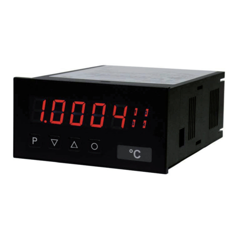
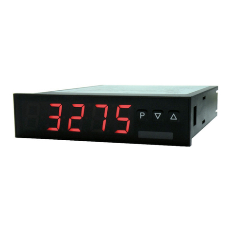
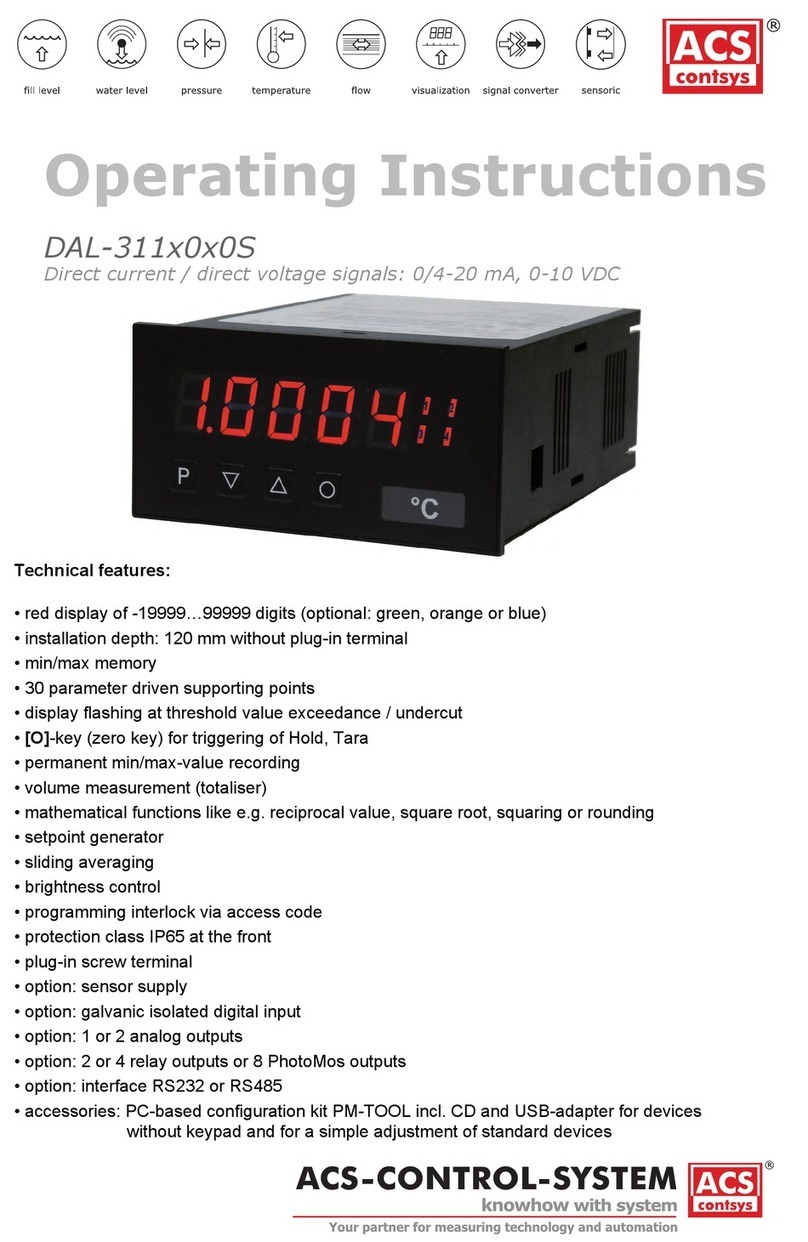
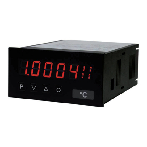
ACS contsys DAL-311-2 Series User manual

Technical features:
• red display of -19999…99999 digits (optional: green, orange or blue display)
• installation depth: 120 mm without plug-in terminal
• min/max memory
• optical threshold value indication at threshold value exceedance / undercut
• permanent min/max-value recording
• brightness control
• programming interlock via access code
• protection class IP65 at the front
• plug-in terminal
• option: 1 or 2 analog outputs
• option: 2 or 4 relay outputs or 8 PhotoMos outputs
• option: interface RS232 or RS485
• accessories: PC-based configuration kit PM-TOOL incl. CD and USB-adapter for devices
without keypad and for a simple adjustment of standard devices
User manual M3
Pt100 3-/4-wire -200.0°C…850.0°C / -328.0°F…1562.0°F
96x48
M3_1CGB.pdf update: 02.04.2015
Operating Instructions
DAL-311x2x0S
Pt100 3-/4-wire -200,0°C…850,0°C / -328,0°F…1562,0°F

ACS-CONTROL-SYSTEM GmbH l Lauterbachstr. 57 l D-84307 Eggenfelden l www.acs-controlsystem.de l [email protected]
2
Order code
power supply
0 100-240V AC
2 10...40V DC galvanic seperated
3 100-240V AC with sensor supply 24V DC/50mA and digital input 1)
4 10...40V DC galvanic seperated with sensor supply 24V DC/50mA and digital input 1)
Y other voltages
function input
2 Pt100 input, 3 + 4-wire up to 850°C
function output
A display + 2 relay outputs (changeover)
B display + 4 relay outputs
C display with analog output 0-10V/4-20mA, switchable
D display + 2 relay with analog output 0-10V/4-20mA, switchable
E display + 4 relay with analog output 0-10V/4-20mA, switchable
Y others outputs
0 standard conguration
S standard, protection IP65
DAL-311
1) sensor supply
only at 0/4...20 mA,
0...10V DC input
Note
S02

ACS-CONTROL-SYSTEM GmbH l Lauterbachstr. 57 l D-84307 Eggenfelden l www.acs-controlsystem.de l [email protected] 3
Contents
1
1. Brief description 2
2. Assembly 3
3. Electrical connection 4
4. Function description and operation 5
4.1. Programming software PM-TOOL 6
5. Setting up the device 7
5.1. Switching on 7
5.2. Standard parameterisation (flat operation level) 7
Value assignment for the triggering of the signal input
5.3. Programming interlock „RUN“ 9
Activation/Deactivation of the programming interlock or change into
professional
or flat operation level
5.4. Extended parametersation (professional operation level) 10
5.4.1. Signal input parameters „INP“ 10
Value assignment for the triggering of the signal input
5.4.2. General device parameters „FCT“ 12
Superior device functions like min/max permanent, brightness control, as well as the control of
the keyboard layout
5.4.3. Safety parameters „COD“ 14
Assignment of user and master code to lock or to receive access to defined parameter such as
analog output and alarms, etc.
5.4.4. Serial parameters „ser“ 15
Parameter for interface definition
5.4.5. Analog output parameters „Out“ 16
Analog output functions
5.4.6. Relay functions „rel“ 19
Parameter for setpoint definition
5.4.7. Alarm parameters „AL1…AL4“ 21
Actuator and dependencies of the alarms
6. Reset to factory settings 22
Reset parameters onto the delivery state
7. Alarms / Relays 23
Functional principle of the switching outputs
8. Interfaces 24
Connection RS232 and RS485
9. Technical data 25
10. Safety advices 27
11. Error elimination 28

ACS-CONTROL-SYSTEM GmbH l Lauterbachstr. 57 l D-84307 Eggenfelden l www.acs-controlsystem.de l [email protected]
4
1. Brief description
2
1. Brief description
The panel meter instrument M3-1C is a 5-digit device for Pt100 sensors and a visual threshold value
monitoring via the display. The configuration happens via four keys at the front or by the optional PC
software PM-TOOL. The integrated programming interlock prevents unrequested changes of parameters
and can be unlocked again with an individual code. Optional the following functions are available: two
analog outputs and interfaces for further evaluating in the unit.
With help of the galvanic isolated setpoints (optional), free adjustable limit values can be controlled and
reported to a superior master display.
The electrical connection is done via plug-in terminals on the back side.
Selectable functions like e.g. the recall of the min/max-value, a direct threshold value regulation during
operation mode, complete the modern device concept.
The panel meter instrument DAL-311 is a 5-digit device for Pt100 sensors and a visual
threshold value monitoring via the display. The conguration happens via 4 keys at the front or via the
optional PC software PM-TOOL. The integrated programming interlock prevents unrequested changes of
parameters and can be unlocked again with an individual code. Optional the following functions are
available: a supply for the sensor, a digital input for triggering of Hold (Tara), two analog outputs and
interfaces for further evaluating in the unit.
With help of the galvanic isolated setpoints (optional), free adjustable limit values can be controlled and
reported to a superior master display.
The electrical connection is done via plug-in terminals on the back side.
Selectable functions like e.g. the recall of the min/max-value, an averaging of the measuring signals, a
nominal presetting or setpoint presetting, a direct threshold value regulation during operation mode and
further measuring setpoints for linearisation, complete the modern device concept.

ACS-CONTROL-SYSTEM GmbH l Lauterbachstr. 57 l D-84307 Eggenfelden l www.acs-controlsystem.de l [email protected] 5
2. Assembly
3
2. Assembly
Sealing
48,0
3,0
139,0
M3
Gap for physical unit
1. After removing the fixing elements, insert the device.
2. Check the seal to make sure it fits securely.
3. Click the fixing elements back into place and tighten the clamping screws by hand. Then use a
screwdriver to tighten them another half a turn.
CAUTION! The torque should not exceed 0.1 Nm!
The dimension symbols can be exchanged before installation via a channel on the side!
Please read the Safety advices on page 27 before installation and keep this user manual for future reference.

ACS-CONTROL-SYSTEM GmbH l Lauterbachstr. 57 l D-84307 Eggenfelden l www.acs-controlsystem.de l [email protected]
6
3. Electrical connection
4
3. Electrical connection
Type M3-1TR5B.010C.W70BD supply 10-40 VDC, galv. Isolated, 18-30 VAC
Type M3-1TR5B.010C.S70BD supply 100-240 VAC, DC ± 10%
Type DAL-311x2x0S
Type DAL-311x2x0S

ACS-CONTROL-SYSTEM GmbH l Lauterbachstr. 57 l D-84307 Eggenfelden l www.acs-controlsystem.de l [email protected] 7
5
4. Function and operation description
Keys for up and down navigation in the menu group level.
Change to menu level.
Change into menu level or break-off in value input.
Parameterisation-
level Adjustment of the value / the setting.
Keys for up and down navigation in the menu level.
DescriptionKey
Change into operation mode or back into menu level.
To confirm the changes made at the parameterization level.
Change into operation mode.
Change to parameterisation level and deposited values.
Menu-group-level
Menu-level
Level
Operation
The operation is divided into three different levels.
Menu level (delivery status)
This level was designed for the standard settings of the device. Only menu items which are sufficent to set
the device into operation are displayed. To get into the professional level, run through the menu level and
parameterise prof under menu item RUN.
Menu group level (complete function volume)
Suited for complex applications as e.g. linkage of alarms, setpoint treatment, totaliser function etc. In this
level function groups which allow an extended parameterisation of the standard settings are availabe. To
leave the menu group level, run through this level and parameterise uloc under menu item RUN.
Parameterisation level:
Parameter deposited in the menu item can here be parameterised. Functions, that can be changed or
adjusted, are always signalised by a flashing of the display. Settings that are made in the parameterisation
level are confirmed with [P] and thus saved. Pressing the [O]-key leads to a break-off of the value input and
to a change into the menu level. All adjustments are saved automatically by the device and changes into
operating mode, if no further key operation is done within the next 10 seconds.

ACS-CONTROL-SYSTEM GmbH l Lauterbachstr. 57 l D-84307 Eggenfelden l www.acs-controlsystem.de l [email protected]
8
6
4. Function and operation description
Function chart:
4.1 Parameterisation software PM-TOOL:
Part of the PM-TOOL are the software on CD and an USB-cable with device adapter. The connection
happens via a 4-pole micromatch-plug on the back side of the device, to the PC-side the connection
happens via an USB plug.
System requirements: PC incl. USB interface
Software: Windows XP, Windows VISTA
With this tool the device configuration can be generated, omitted and saved on the PC. The parameters can
be changed via the easy to handle program surface, whereat the operating mode and the possible selection
options can be preset by the program.

ACS-CONTROL-SYSTEM GmbH l Lauterbachstr. 57 l D-84307 Eggenfelden l www.acs-controlsystem.de l [email protected] 9
7
5.1. Switching on
Once the installation is complete, start the device by applying the voltage supply. Before, check once again
that all electrical connections are correct.
Starting sequence
For 1 second during the switching-on process, the segment test (8 8 8 8 8) is displayed followed by an
indication of the software type and, after that, also for 1 second the software version. After the starting
sequence, the device switches to operation/display mode.
5.2. Standard parameterisation: (Flat operation level)
To parameterise the display, press the [P]-key in operating mode for 1 second. The display then changes to
the menu level with the first menu item TYPE.
5. Setting up the device
Setting the decimal point, DOt:
Default: 0.0
The decimal point on the display and the physical unit can be changed with [▲] [▼]. If e.g.
temperature measurement in °C is selected, then you can choose between 0°C and 0.0°C in the
parameterisation level. Confirm with [P], the display then switches back to the menu level
again.
Impedance matching, dot:
Default: 0.0
The value for the sensor calibration is selectable from the smallest to the highest digit with
[▲][▼]and confirmed with [P]. After the last digit the display switches back to the menu level
again. The value calibration for a temperature measurement in °C can be adjusted between
-20.0 and +20.0 and in °F between -36.0 and +36.0. If the type of the measurement is changed
later, then the value is rounded.
Type of temperature metering UNIT:
Default: °c
The temperature can be displayed in °C or in °F. Confirm the selection with [P] and the display
switches back to menu level.
Selection of the input signal, tYPE:
Default: 4l
Available as measuring input types are 3- and 4-wire-Pt100 signals. Confirm the selection with
[P] and the display switches back to menu level.
Parameterisation levelMenu level

ACS-CONTROL-SYSTEM GmbH l Lauterbachstr. 57 l D-84307 Eggenfelden l www.acs-controlsystem.de l [email protected]
10
8
5. Setting up the device
Threshold values / limits, LI-1:
Default: 200.0
This value defines the threshold, that activates/deactivates an alarm.
Setting up the initial value of the analog output, Out.OF:
Default: -200,0
The final value is adjusted from the smallest digit to the highest digit with [▲] [▼]and digit by
digit confirmed with [P]. A minus sign can only be parameterised on the highest digit. After the
last digit, the device changes back into menu level.
Setting up the final value of the analog output, Out.En:
Default: 850.0
The final value is adjusted from the smallest digit to the highest digit with [▲] [▼]and digit by
digit confirmed with [P]. A minus sign can only be parameterised on the highest digit. After the
last digit, the device changes back into menu level.
Hysteresis for limit values, HY-1:
Default: 0.0
The delayed reaction of the alarm is the difference to the threshold value, which is defined by
the hysteresis.
Selection of analog output, Out.rA:
Default: 4-20
Three output signals are available: 0-10 VDC, 0-20 mA and 4-20 mA, with this function, the
demanded signal is selected.
Setting up the display time, SEC:
Default: 1.0
The display time is set with [▲] [▼]. The display moves up in increments of 0.1 up to 1 second
and in increments of 1.0 up to 10.0 seconds. Confirm the selection by pressing the [P] button.
The display then switches back to the menu level again.
Parameterisation levelMenu level
then

ACS-CONTROL-SYSTEM GmbH l Lauterbachstr. 57 l D-84307 Eggenfelden l www.acs-controlsystem.de l [email protected] 11
9
5. Setting up the device
5.3. Programming interlock „RUN“
Master code (4-digit number-combination, free available), A.CodE:
Default: 1234
All parameters can be unlocked with this code, after LOC has been activated under menu item
run. By pressing [P] for 3 seconds in operation mode, the display shows COde and enables the
user to reach all parametes by entering the A.codE. Under run the parameteisation can be
activated permanently by selecting ULOC or ProF, thus at an anew pushing of [P] in operation
mode, the code needs not to be entered again.
User code (4-digit number-combination, free available), U.CodE:
Default: 0000
If this code was set (>0000), all parameters are locked for the user, if LOC has been selected
before under menu item run. By pressing [P] for 3 seconds in operation mode, the display
shows COde. The U.Code needs to be entered to get to the reduced number of parameter sets.
The code has to be entered befor each parameterisation, until the A.Code (Master code) unlocks
all parameters again.
The same applies to LI-2!
Activation / deactivation of the programming lock or completion of the standard
parameterisation with change into menu group level (complete function range), run:
Default: uloc
With the navigation keys [▲] [▼], choose between the deactivated key lock Uloc (works
setting) and the activated key lock Loc, or the change into the menu group level ProF. Confirm
the selection with [P]. After this, the display confirms the settings with "-- - - -", and
automatically switches to operating mode. If Loc was selected, the keyboard is locked. To get
back into the menu level, press [P] for 3 seconds in operating mode. Now enter the CODE (works
setting 1 2 3 4) that appears using [▲] [▼]plus [P] to unlock the keyboard. FAIL appears if the
input is wrong. To parameterise further functions ProF needs to be set. The device confirms this
setting with „-- - - -„and changes automatically in operation mode. By pressing [P] for approx.
3 seconds in operation mode, the first menu group InP is shown in the display and thus confirms
the change into the extended parameterisation. It stays activated as long as ULOC or LOC is
entered in menu group RUN.
Function for threshold value undercut / exceedance, Fu-1:
Default: high
A limit value undercut is selected with Louu (for LOW = lower limit value), a limit value
exceedance with High (for HIGH = higher limit value). If e.g. limit value 1 is on a threshold level
of 100 and allocated with function High, an alarm is activated by reaching of the threshold level.
If the threshold value was allocated to Low, an alarm will be activated by undercutting the
threshold value, as long as the hysteresis is zero.
Parameterisation levelMenu level

ACS-CONTROL-SYSTEM GmbH l Lauterbachstr. 57 l D-84307 Eggenfelden l www.acs-controlsystem.de l [email protected]
12
10
5. Setting up the device
5.4. Extended parametrisation (Professional operation level)
Menu group level
Menu level
5.4.1. Signal input parameters
Setting the decimal point, DOt:
Default: 0.0
The decimal point on the display and the physical unit can be changed with [▲] [▼]. If e.g.
temperature measurement in °C is selected, then you can choose between 0°C and 0.0°C in the
parameterisation level. Confirm with [P], the display then switches back to the menu level
again.
Impedance matching, dot:
Default: 0.0
The value for the sensor calibration is selectable from the smallest to the highest digit with
[▲] [▼]and confirmed with [P]. After the last digit the display switches back to the menu level
again. The value calibration for a temperature measurement in °C can be adjusted between
-20.0 and +20.0 and in °F between -36.0 and +36.0. If the type of the measurement is changed
later, then the value is rounded.
Type of temperature metering UNIT:
Default: °c
The temperature can be displayed in °C or in °F. Confirm the selection with [P] and the display
switches back to menu level.
Selection of the input signal, tYPE:
Default: 4l
Available as measuring input types are 3- and 4-wire-Pt100 signals. Confirm the selection with
[P] and the display switches back to menu level.
Parameterisation levelMenu level

ACS-CONTROL-SYSTEM GmbH l Lauterbachstr. 57 l D-84307 Eggenfelden l www.acs-controlsystem.de l [email protected] 13
5. Setting up the device
11
Input variable of process value, SIG.in:
Default: a.meas
With this parameter, the device can be controlled via the analog input signals a.meas = 0-20 mA,
4-20 mA or 0-10 VDC or via the digital signals of the interface M.bus = RS232/RS485 (Modbus
protocol). With [P] the selection is confirmed and the device changes into menu level.
Display overflow, dI.OUE:
Default: 99999
With this function the display overflow (_ _ _ _ _) can be defined on a definite value.
Back to menu group level, rEt:
With [P] the selection is confirmed and the device changes into menu group level „–INP–“.
Device undercut, dI.Und:
Default: -i9999
With this function the device undercut (_ _ _ _ _) can be defined on a definite value. Exception is
input type 4-20 mA, it already shows undercut at a signal <1 mA, so a sensor failure is marked.
Setting up the display time, SEC:
Default: 1.0
The display time is set with [▲] [▼]. The display moves up in increments of 0.1 up to 1 second
and in increments of 1.0 up to 10.0 seconds. Confirm the selection by pressing the [P] button.
The display then switches back to the menu level again.
Parameterisation levelMenu level
then

ACS-CONTROL-SYSTEM GmbH l Lauterbachstr. 57 l D-84307 Eggenfelden l www.acs-controlsystem.de l [email protected]
14
5. Setting up the device
12
5.4.2. General device parameters
Brightness control, Light:
Default: 15
The brightness of the display can be adjusted in 16 levels from 00 = very dark to 15 = very
bright via this parameter or alternatively via the navigation keys from the outside. During the
start of the device the level that is deposited under this parameter will always be used, even
though the brightness has been changed via the navigation keys in the meantime.
Display, dISPL:
Default: actua
With this function the current measuring value or the min/max value can be allocated to the
display. With [P] the selection is confirmed and the device changes into menu level.
Rounding of display values, round:
Default: 00001
This function is for instable display values, where the display value is changed in
increments of 1, 5, 10 or 50. This does not affect the resolution of the optional outputs. With [P]
the selection is confirmed and the device changes into menu level.
Display time, DISEC:
Default: 01.0
The display is set up with [▲] [▼]. Thereby it switches up to 1 second in increments of 0.1
seconds and up to 10.0 seconds in increments of 1.0. With [P] the selection is confirmed and
the device changes into menu level.
Parameterisation levelMenu level
Menu group level
Menu level
then

ACS-CONTROL-SYSTEM GmbH l Lauterbachstr. 57 l D-84307 Eggenfelden l www.acs-controlsystem.de l [email protected] 15
5. Setting up the device
13
Special function [O]-key, tASt.4:
Default: no
For the operation mode, special functions can be deposited on the [O]-key. This function is
activated by pressing the key. Set.OF adds a defined value to the currently displayed value.
EHt.rE deletes the min/max-memory. ActuA shows the measuring value for approx. 7 seconds,
after this the device switches back onto the parameterised display value. If nowas selected, the
[O]-key is without any function in the operation mode.
Display flashing, FLASH:
Default: no
A display flashing can be added as additional alarm function either to single or to a combination
of off-limit condition. With no, no flashing is allocated.
Assignment (deposit) of key functions, tASt:
Default: no
For the operation mode, special functions can be deposited on the navigation keys [▲] [▼], in
particular this function is made for devices in housing size 48x24mm which do not have a 4th
key ([O]-key). If the min/max-memory was activated by EHtr, all measured min/max-values are
saved during operation and can be recalled via the navigation keys. The values get lost by
restart of the device. If the threshold value correction LI.12 or LI.34 is choosen, the values of the
threshold can be changed during operation without disturbing the operating procedure. Under
Light the brightness can be changed during operation. If no is selected, the navigation keys are
without any function in the operation mode.
Back to menu group level, rEt:
With [P] the selection is confirmed and the device changes into menu group level „–fct–“.
Parameterisation levelMenu level

ACS-CONTROL-SYSTEM GmbH l Lauterbachstr. 57 l D-84307 Eggenfelden l www.acs-controlsystem.de l [email protected]
16
5. Setting up the device
14
Release/lock alarm parameters, AL.LEU:
Default: all
This parameter describes the user release/user lock of the alarm:
- LIMIt: here only the range of value of the threshold values 1-4 can be changed
-ALrM.L: here the range of value and the alarm trigger can be changed
-ALL: all alarm parameters are released
-no: all alarm parameters are locked
Release/lock analog output parameter, Out.LE:
Default: all
Analog output parameter can be locked or released for the user:
-En-oF: the initial or final value can be changed in operation mode
-Out.EO: the output signal can be changed from e.g. 0-20 mA to 4-20 mA or 0-10 VDC
-ALL: analog output parameters are released
-no: all analog output parameters are locked
Back to menu group level, rEt:
With [P] the selection is confirmed and the device changes into menu group level „–COD–“.
Master code, A.Code:
Default: 1234
By entering A.CodE the device will be unlocked and all parameters are released.
User code U.Code:
Default: 0000
Via this code reduced sets of parameters can be set free. A change of the U.CodE can be done
via the correct input of the A.CodE (master code).
Parameterisation levelMenu level
Menu group level
5.4.3. Safety parameters
Menu level

ACS-CONTROL-SYSTEM GmbH l Lauterbachstr. 57 l D-84307 Eggenfelden l www.acs-controlsystem.de l [email protected] 17
5. Setting up the device
15
Menu group level
5.4.4. Serial parameters
Menu level
Timeout, tIout:
Default: 000
The monitoring of the data transfer is parameterised in seconds up to max. 100 seconds; there
is no monitoring with an input of 000. The timeout is adjusted from the smallest to the largest
digit with the navigation keys [▲] [▼]and confirmed digit per digit with [P]. After the last digit
the device changes back into menu level.
ModBus operating modes, b.mode:
Default: ascii
There are two different types of operating modes: ASCII and rtu. Modbus transfers no binary
cycle, but the ASCII-Code. Thus it is directly readable, however the data throughput is smaller
in comparison to the RTU. Modbus RTU (RTU = Remote Terminal Unit) transfers the data in
binary-coded. This leads to a good data troughput, even though the data cannot be evaluated
directly, as they first need to be transfered into a readable format.
Device address, ADDR:
Default: 001
The device address is adjusted from the smallest to the largest digit with the navigation keys
[▲] [▼]and confirmed digit per digit with [P]. A device address up to max. 250 is available.
Interface data: Baudrate 9600 bit/s, 8 databyte, 1 stopbit, no parity (8n1).
Back to menu group level, rEt:
With [P] the selection is confirmed and the device changes into menu group level „–SER–“.
Parameterisation levelMenu level

ACS-CONTROL-SYSTEM GmbH l Lauterbachstr. 57 l D-84307 Eggenfelden l www.acs-controlsystem.de l [email protected]
18
5. Setting up the device
16
Menu group level
5.4.5. Analog output parameters for analog output 1
Menu level
Setting the final value of the analog output, Out.En:
Default: 850.0
The final value is adjusted from the smallest to the highest digit with [▲] [▼]and confirmed
digit per digit with [P]. A minus sign can only be parameterised on the highest digit. After the
last digit the device changes back into menu level.
Selection analog output, Out.rA:
Default: 4-20
Three output signals are available 0-10 VDC, 0-20 mA and 4-20 mA. Select the desired signal
with this function.
Selection reference of analog output, OutPt:
Default: actua
The analog output signal can refer to different functions, in detail these are the current
measurand, the min-value or the max-value. With [P] the selection is confirmed and the device
changes into menu level.
Setting the initial value of the analog output, Out.OF:
Default: -200.0
The initial value is adjusted from the smallest to the highest digit with [▲] [▼]and confirmed
digit per digit with [P]. A minus sign can only be parameterised on the highest digit. After the
last digit the device changes back into menu level.
Parameterisation levelMenu level

ACS-CONTROL-SYSTEM GmbH l Lauterbachstr. 57 l D-84307 Eggenfelden l www.acs-controlsystem.de l [email protected] 19
5. Setting up the device
17
Overflow behaviour, O.FLoU:
Default: edge
To recognise and evaluate faulty signals, e.g. by a controller, the overflow behaviour of the
analog output can be defined. As overflow can be seen either EdGE, that means the analog
output runs on the set limits e.g. 4 and 20 mA, or to.OFF (input value smaller than initial value,
analog output switches on e.g. 4 mA), to.End (higher than final value, analog output switches on
e.g. 20 mA). If to.MIn or to.MAX is set, the analog output switches on the smallest or highest
possible binary value. This means that values of e.g. 0 mA, 0 VDC or values higher than 20 mA
or 10 VDC can be reached. With [P] the selection is confirmed and the device changes into
menu level.
Back to menu group level, rEt:
With [P] the selection is confirmed and the device changes into menu group level „–out–“.
Parameterisation levelMenu level
Menu group level
Analog output parameters for analog output 2
Selection reference of analog output, Ou2Pt:
Default: actua
The analog output signal can refer to different functions, in detail these are the current
measurand, the min-value or the max-value. If HoLd was selected, the signal of the analog
output will be kept. It can be continued processing after a deactivation of Hold. With [P] the
selection is confirmed and the device changes into menu level.
Parameterisation levelMenu level
Menu level

ACS-CONTROL-SYSTEM GmbH l Lauterbachstr. 57 l D-84307 Eggenfelden l www.acs-controlsystem.de l [email protected]
20
5. Setting up the device
18
Overflow behaviour, Ou2.fl:
Default: edge
To recognise and evaluate faulty signals, e.g. by a controller, the overflow behaviour of the
analog output can be defined. As overflow can be seen either EdGE, that means the analog
output runs on the set limits e.g. 4 and 20 mA, or to.OFF (input value smaller than initial value,
analog output switches on e.g. 4 mA), to.End (higher than final value, analog output switches on
e.g. 20 mA). If to.MIn or to.MAX is set, the analog output switches on the smallest or highest
possible binary value. This means that values of e.g. 0 mA, 0 VDC or values higher than 20 mA
or 10 VDC can be reached. With [P] the selection is confirmed and the device changes into
menu level.
Setting the initial value of the analog output, Ou2.of:
Default: -200.0
The initial value is adjusted from the smallest to the highest digit with [▲] [▼]and confirmed
digit per digit with [P]. A minus sign can only be parameterised on the highest digit. After the
last digit the device changes back into menu level.
Back to menu group level, rEt:
With [P] the selection is confirmed and the device changes into menu group level „–ou2–“.
Selection analog output, Ou2.rA:
Default: 4-20
3 output signals are available 0-10 VDC, 0-20 mA and 4-20 mA. Select the desired signal with
this function.
Setting the final value of the analog output, Ou2.En:
Default: 850.0
The final value is adjusted from the smallest to the highest digit with [▲] [▼]and confirmed
digit per digit with [P]. A minus sign can only be parameterised on the highest digit. After the
last digit the device changes back into menu level.
Parameterisation levelMenu level
Table of contents
Other ACS contsys Measuring Instrument manuals

ACS contsys
ACS contsys Flowcont UN User manual
ACS contsys
ACS contsys DAP-311 0 0S Series User manual

ACS contsys
ACS contsys RCE 300 User manual

ACS contsys
ACS contsys SAT User manual

ACS contsys
ACS contsys DAL-311 5 0S Series User manual

ACS contsys
ACS contsys DAL-311x0x0S User manual

ACS contsys
ACS contsys DAL-311x3x0S User manual

ACS contsys
ACS contsys Sonicont USN4SP User manual
Popular Measuring Instrument manuals by other brands

Wildlife Acoustics
Wildlife Acoustics SMART MIC-1 user guide

VDO
VDO VIEWLINE TACHOMETER WITHOUT LCD Product information

Endress+Hauser
Endress+Hauser Proline Prosonic Flow P 500 Functional safety manual

Flow
Flow In-Home Display user guide

Amiko
Amiko TSC-1000 user manual

Omntec
Omntec OEL8000II owner's manual