ACS contsys Thermocont TS4S User manual
07.17
Technical manual
Applications
General applications in
• Machinery and plant engineering
• Air-conditioning and refrigeration plant engineering
• Hydraulic and pneumatic systems
• Process industry
• Environmental technology
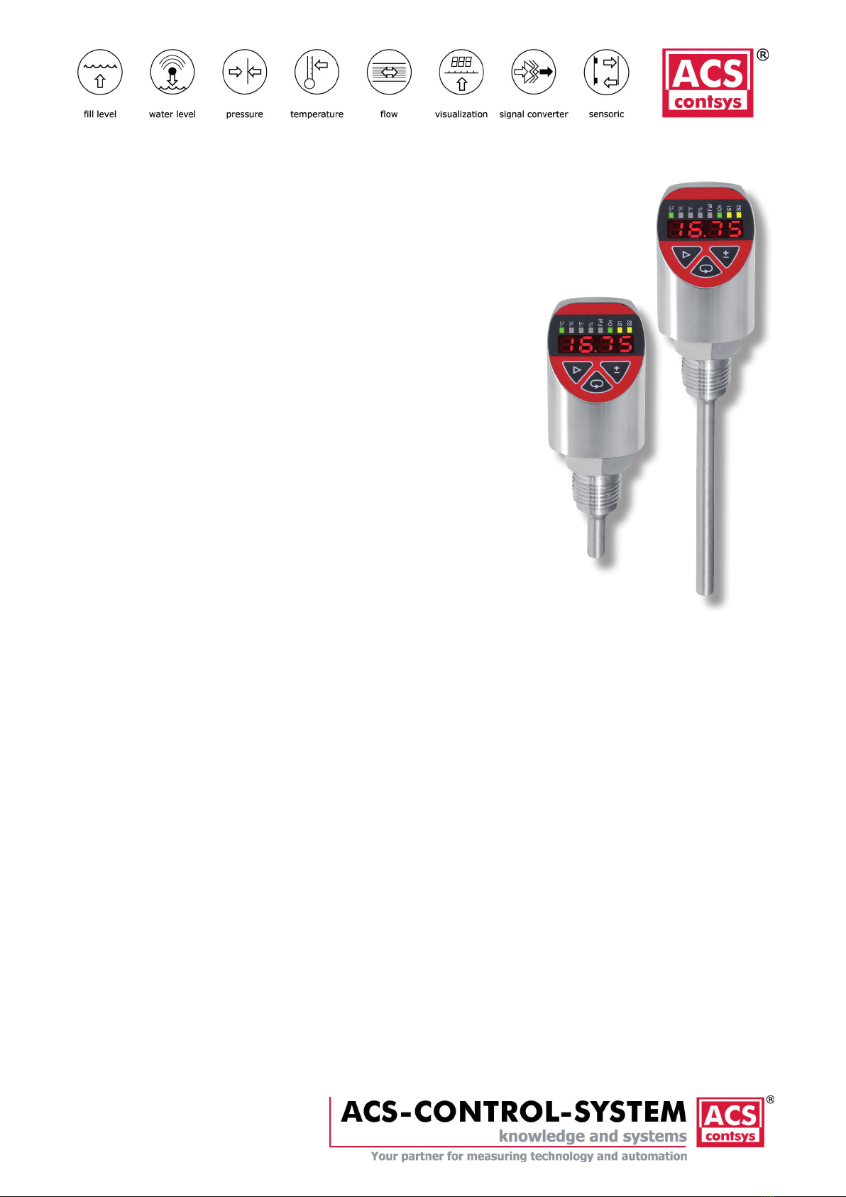
Thermocont TS4S
Temperature switch for general applications
Monitoring of temperatures
in gases, vapors, liquids and dust
Main features
Wide range of applications
• Wide process temperature range –99,9°C to +500°C
• High process pressure tightness up to 100 bar
• Wide variety of process connections
• High protection class IP65 / IP67
• Wide environmental temperature range –40°C to +85°C
Long term stable temperature sensor platinum Pt100 class A – DIN EN
60751
Increased process safety and cost saving by self-supervising
measuring system for drift monitoring and redundancy function
High accuracy – characteristic deviation ≤ 0,5% of measuring range
Short response time
Integrated evaluation electronic
• Digital display, function LED’s, keyboard
• 2x PNP switch output
• 1x current output 4…20mA
• Connector plug M12
High operating comfort
• Enclosure and display rotatable for optimal operability in each
installation position
• Robust high brightness LED display for best readability
• 3-key operation without additional assistance with tactile feedback

ACS-CONTROL-SYSTEMGmbHlLauterbachstr.57lD-84307Eggenfeldenlwww.acs-controlsystem.del[email protected]
2
You have purchased a high-grade and modern measuring device of ACS-CONTROL-SYSTEM GmbH.
We want to give thanks for your purchase and for your condence to us.
The actual technical manual includes instructions for installation, electrical connection and inauguration,
as well as the technical data of the device.
Modications, that answer the purpose of the technical progress, are reserved by
ACS-CONTROL-SYSTEM GmbH without prior notice.
If a question occurs, that can‘t be answered by the listed informations, please call on our technicians
All rights reserved

ACS-CONTROL-SYSTEMGmbHlLauterbachstr.57lD-84307Eggenfeldenlwww.acs-controlsystem.del[email protected] 3
1 Index
1 Systemdescription................................................4
1.1 Intended use................................................... 4
1.2 Field of application ........................................... 4
1.3 System components ......................................... 5
1.4 Function ......................................................... 5
2 Safety notes . . . . . . . . . . . . . . . . . . . . . . . . . . . . . . . . . . . . . . . . . . . . . . . . . . . . . 6
2.1 Operational safety............................................ 6
2.2 Installation, connection, commissioning, operation6
3 Installation......................................................7
3.1 Installation place ............................................. 7
3.2 Process and environmental temperature ............. 8
3.3 Installation notes ............................................. 8
4 Electricalconnection ..............................................9
4.1 Potential equalization – earthing ........................ 9
4.2 Connection cable ............................................. 9
4.3 Supply voltage ................................................ 9
4.4 Load resistor .................................................. 9
4.5 Switch output.................................................. 9
4.6 Connection scheme .......................................... 10
5 Operation......................................................11
5.1 Operation and display parts............................... 11
5.2 Function modes ............................................... 11
5.3 Switch output S1 / S2 ...................................... 12
5.4 Current output ................................................ 13
5.5 Self-supervising function................................... 14
5.6 Menu structure ................................................ 15
5.7 Parameter overview ......................................... 18
5.8 Error indication at operation .............................. 21
5.9 Software history .............................................. 21
6 Service........................................................22
6.1 Maintenance.................................................... 22
6.2 Dismounting.................................................... 22
6.3 Repair ............................................................ 22
6.4 Return............................................................ 22
6.5 Disposal ......................................................... 22
7 TechnicalData ..................................................23
7.1 Auxiliary power supply...................................... 23
7.2 Output Switch output ....................................... 23
7.3 Output current 4…20mA ................................... 23
7.4 Measuring accuracy.......................................... 23
7.5 Process conditions............................................ 24
7.6 Environmental conditions .................................. 25
7.7 Materials - process wetted ................................ 25
7.8 Materials - not process wetted ........................... 25
8 Dimensiondrawings..............................................26
8.1 Terminal enclosure ........................................... 26
8.2 Process connection........................................... 26
8.3 Sensor tube .................................................... 27
9 Orderinginformation.............................................28
9.1 Order code...................................................... 28
9.2 Additional options ............................................ 29
9.3 Accessories ..................................................... 29

ACS-CONTROL-SYSTEMGmbHlLauterbachstr.57lD-84307Eggenfeldenlwww.acs-controlsystem.del[email protected]
4
1 System description
1.1 Intended use
The device is an electronic temperature switch for monitoring, control as well as continuous
measurement of temperatures in gases, vapors, liquids and dusts.
The operational reliability of the device is ensured only at the intended use.
1.2 Field of application
Due to the device construction with
• Process temperature from up to –99,9°C to +500°C
• Process pressures up to 100 bar
• Process contacting material stainless steel V4A
as well as the availability of a variety of process connections like
• connection for compression tting
• thread connections ISO 228-1
• thread connection ISO 228-1 with front-ush O-ring gasket
the device is especially suitable for the use for
• machinery and plant engineering
• air-conditioning and refrigeration plant engineering
• hydraulic and pneumatic systems
• process industry
• environmental technology
• paint and coating industry
The temperature switch is suitable for demanding measuring requirements.
Due to its high accuracy and the high exibility of conguration, the device can be suited a wide
variety of applications.
Compared with temperature sensors, which are calibrated cyclic, the process safety increases when
using the temperature switch with self-supervision. At cyclic calibration an occurring drift will be
also detected, but an undened time it has been produced with a drift aected sensor. Because the
device generates a signal immediately at exceedance of the set drift limit, it must not be waited until
to the end of the calibration interval. Thus the process safety and with this the product quality will be
improved signicantly.
Besides the increased process safety, the use of the temperature switch with self-supervision
allows substantial cost savings. Due to the use of two redundantly working sensors, which are
mutually monitored, the calibration intervals can be increased und thus calibrations can be saved.
Although the device is a little bit more expensive at the acquisition costs than a standard temperature
sensor, when saving only one calibration the acquisition price will pay o shortly.
The pressure switch with front-ush O-ring gasket has been specically designed for the measurement
of viscous, paste-like, adhesive, crystallizing, particle-laden and contaminated media. The process
connection is supplied with a positive seal. A reliable, dead-space free sealing between the process
connection and the process adapter resp. measuring medium is thus assured.
The robust design and the high-quality workmanship turns the device into a very high quality
product, which even the most adverse environmental conditions cannot aect, whether the lowest
temperatures when used outdoors, extreme shock and vibration or aggressive media.
A captive laser marking of the type label ensures the identiability throughout the entire lifetime of
the device.
Obviously is the optional marking of a measurement point designation resp. TAG, a customer label or
of a neutral type label, of course also per laser marking.
A LABS-free resp. silicone-free version, a factory calibration with calibration certicate and a customer
specic conguration resp. preset is also optionally available like a material test certicate EN10204
3.1 or factory certications for drink water resp. food suitability.

ACS-CONTROL-SYSTEMGmbHlLauterbachstr.57lD-84307Eggenfeldenlwww.acs-controlsystem.del[email protected] 5
Customer specic special versions can be realized short-term on request, e.g.
• software adaption (menu navigation, special functions, etc.),
• changed terminal assignment resp. connector orientation,
• design adaption of the user surface,
• special designs for the process connection
thread connection acc. to ANSI NPT, DIN 13 or JIS
thread connection ISO 225-1 - M18x1,5, inner thread
• other process materials, e.g. Hastelloy, Titan, etc.
• surface coating, e.g. PTFE
• special adjustment
1.3 System components
The device consists on the components:
• Sensor tube, as junction point in direct contact with the applied medium.
• Process connection, for installation into the wall of the container or of the pipeline.
• Neck tube, for decoupling of the terminal enclosure from high process temperatures.
• Terminal enclosure, rotatable by 300°, for protection of the integrated signal processing
electronic and for the electrical connection.
The components cannot be separated by the user.
1.4 Function
1.4.1 Measuring principle
The detection of the process temperature is made by the measurement of the temperature dependent
change of resistance of a precise and long term stable resistive temperature sensor Pt100 class A,
which is installed in the sensor tube.
1.4.2 Self-supervision function
At the self-supervising measuring system with drift monitoring and redundancy function the recording
of the Temperature is made additionally by a semiconductor temperature sensor.
Because of the parallel measurement with two physically dierent thermal coupled sensor elements,
the device detects impermissible drifts of a sensor and errors at the temperature measurement
automatically.
At the failure of one of the two sensor elements the temperature measurement can be also continued
with the second element, what realizes a redundancy function.
1.4.3 Signal processing
The temperature signal is converted by the temperature sensor into an electrical signal and processed
by the integrated evaluation electronic according to the respective preferences:
• The measuring value is monitored by two PNP switch outputs for exceedance of limit values.
• The measuring value is converted into a continuous current signal 4...20mA.
• The measuring value is displayed at the robust high brightness LED display.
• Several function LED’s signal the device state.
• All settings can be changed comfortable and easy by a 3-key operation without additional
assistance with tactile feedback.
The device includes numerous functions to the adaption to nearly each measuring task:
• Adjustable measuring range down to 25% of nominal measuring span
• Integrated unit conversion °C – °K – °F
• Peak value memory minimum – maximum
• Error memory for fast failure analysis
• Hysteresis or window function, time delay and working principle of the switch outputs
• Error indication function to switch output, current output and display
• Simulation of the switch outputs and the current output

ACS-CONTROL-SYSTEMGmbHlLauterbachstr.57lD-84307Eggenfeldenlwww.acs-controlsystem.del[email protected]
6
2 Safety notes
2.1 Operational safety
The device is safely built and tested according to state-of-the-art technology and has left the factory in
perfect condition as regards technical safety.
The device meets the legal requirements of all relevant EU directives. This is conrmed by attaching
the CE mark.
This measuring device meets article 4 (3) of the EU directive 2014/68/EU (pressure equipment device
directive) and is designed and produced in good engineer practice.
2.2 Installation, connection, commissioning, operation
Installation, electrical connection, commissioning and operation of the device must be made by a
qualied and authorized expert according to the information’s in this technical manual and the relevant
standards and rules. This expert must have read and understood this technical manual and especially
the safety notes.
The device may only be used within the permitted operation limits that are listed in this technical
manual. Every use besides these limits as agreed can lead to serious dangers.
The materials of the device must be checked for compatibility with the respective application
requirements (contacting materials, process temperature) before use. An unsuitable material can lead
to damage, abnormal behavior or destruction of the device and to the resulting dangers.
The sensors may not be used as sole device for prevention of dangerous conditions in machines and
plants.
Using the device in a manner that does not fall within the scope of its intended use, disregarding
this instruction, using under-qualied personnel, or making unauthorized alterations releases the
manufacturer from liability for any resulting damage. This renders the manufacturer‘s warranty null
and void.
ACS-CONTROL-SYSTEMGmbHlLauterbachstr.57lD-84307Eggenfeldenlwww.acs-controlsystem.del[email protected] 7
3 Installation
The correct function of the device within the specic technical data can only be guaranteed, if
the permitted process and environmental temperatures (see chapter „Technical data“) will not be
exceeded.
3.1 Installation place
The choice of the place of installation of the sensor and the length of the sensor tube are of
considerable importance for the quality and the reliability of the measuring results.
If the sensor isn’t installed deeply enough, an error in the measured temperature can occur because of
the dierent process ow temperature at the pipeline wall and the heat transfer along the sensor tube.
The appearance of the error should not be ignored if a considerable dierence between process
temperature and environmental temperature exists.
Thus it is suggested to use an installation length of at least 80...100 mm.
The shorter the installation length, the greater is the deviation against the real medium temperature
caused by the heat transfer.
The following general recommendations can be applied as approximately guideline:
• In liquids, the sensor tube length should be 5...6 times greater than the diameter of the
sensor tube plus the sensitive length of 50 mm.
• In steam, air and gases, the sensor tube length should be 10...15 times greater than the
diameter of the sensor tube plus the sensitive length of 50 mm.
In pipelines with small diameter the tip of the sensor tube should reach the axis line, that means the
middle of the pipeline, and if possible additionally a little more.
By isolating the external parts of the sensor, the eect caused by too low installation depth, can be
reduced.
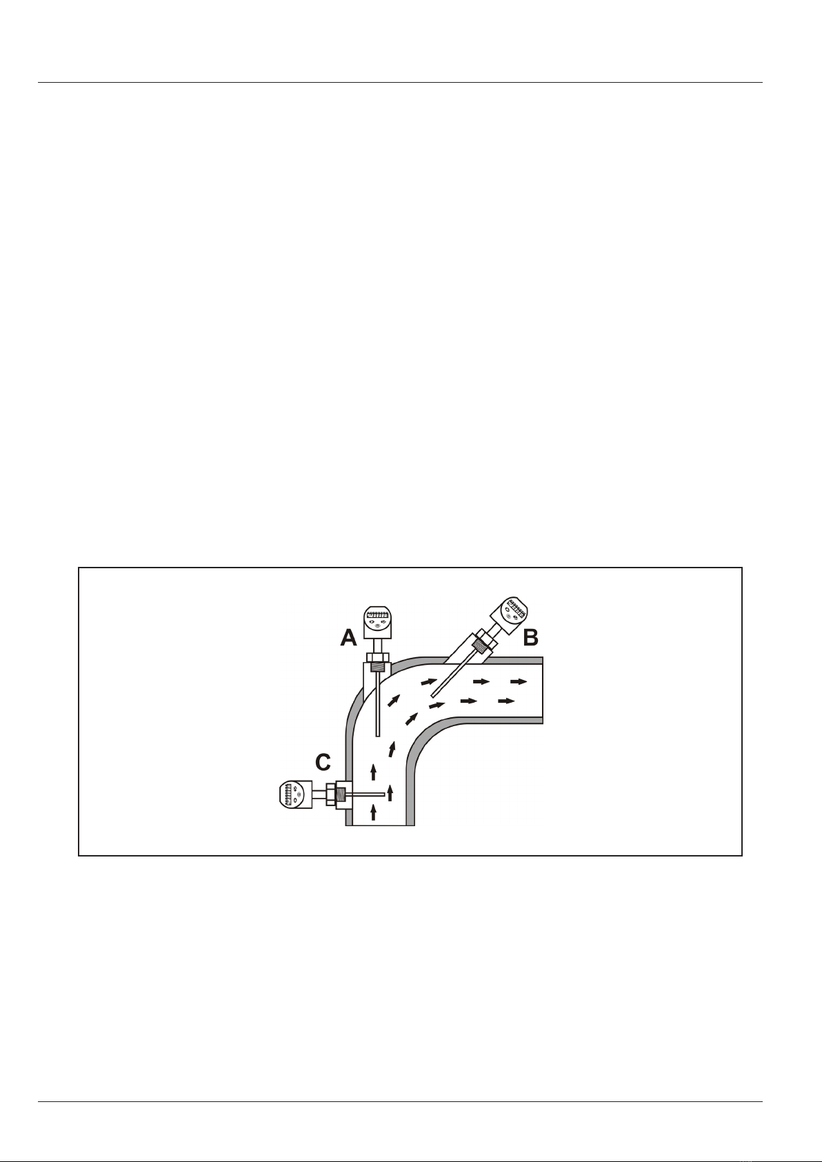
An additional solution for optimizing the measurement quality of small formatted pipelines could be
the installation of the sensor tube diagonal to the pipeline longitudinal axis or the installation of the
sensor tube in the pipeline arc.
A) In the pipe arc against the ow direction
B) In small pipes diagonal against the ow direction
C) Vertical to the ow direction
At a horizontal installation, especially in hygienic applications, the probe should be installed with a
decline against the horizontal of minimum 3°, to ensure a self-emptying.
ACS-CONTROL-SYSTEMGmbHlLauterbachstr.57lD-84307Eggenfeldenlwww.acs-controlsystem.del[email protected]
8
3.2 Process and environmental temperature
At high process temperatures a heat transfer to the terminal enclosure can be reduced by isolation of
the medium carrying part of the plant or by the use of a neck tube.
3.2.1 Neck tube
The neck tube is used to decouple the temperatures between medium and the terminal enclosure in
order to reduce the temperature at the terminal enclosure.
By using a neck tube at extreme process temperatures it can be achieved, that the permitted
environmental temperature range in the area of the terminal enclosure will not be exceeded.
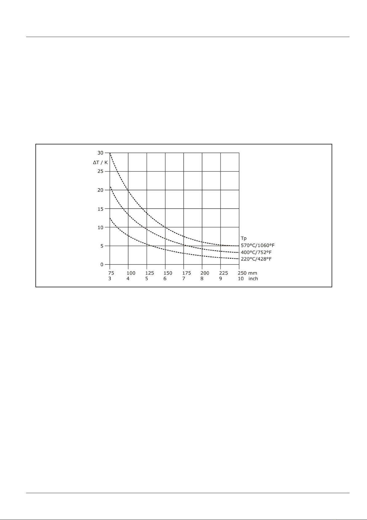
The length of the needed neck tube depends on the height of the process temperature and the
respective installation situation.
Like shown in the graphic, the length of the neck tube can considerably inuence the temperature at
the terminal enclosure.
The graphic is only an approximately guide, because the real heating of the terminal enclosure can be
inuenced by additional factors, e.g. a system isolation or also the position of the terminal enclosure.
3.3 Installation notes
Drive the system pressure free prior installation resp. deinstallation of the sensor.
Be sure that no medium is owing in the system. At extreme system or medium temperatures there
could exist serious dangers.
The screw-in of the thread process connection by using the terminal enclosure, the connection plug
resp. the connection cable is not permitted.
The tightening of the thread process connection may only be done at the hexagon by a suitable
spanner and with the maximum permitted torque strength (see chapter „Technical data“).

ACS-CONTROL-SYSTEMGmbHlLauterbachstr.57lD-84307Eggenfeldenlwww.acs-controlsystem.del[email protected] 9
4 Electrical connection
The electrical connection of the device must be carried out according to the respective country specic
standards.
Incorrect installation or adjustment could cause applicationally conditioned risks.
Warning!
The instrument may only be installed if the supply voltage is switched o.
4.1 Potential equalization - earthing
The device must be grounded.
The earthing can be carried out by the metallic process connection.
The metallic parts of the device are electrically connected with the socket of the plug M12.
4.2 Connection cable
Use only shielded signal and measurement wires and install these wires separated from power leading
wires.
Connect the cable shield of a connected cable only at one side to earth, ideally at the installation place
of the device.
4.3 Supply voltage
The voltage applied to the terminal contacts may not exceed the maximum permitted supply voltage
to avoid damage of the electronic.
The maximum permitted supply voltage range is:
All versions 10,5…35VDC
All connections are reverse polarity protected.
4.4 Switch output
Warning!
Inductive loads at the PNP switch outputs, e.g. relays, contactors or magnetic vents may only be used
with a free-wheeling diode or a RC protection circuit to avoid high voltage peaks.
Note!
For inauguration it is suggested, to deactivate all connected control devices, to avoid unwanted control
reactions.
The load at the PNP switch output will be connected to the terminal +L of the supply voltage by a
semiconductor switch contactless and by this bounce-free.
At an activated switch state a positive signal near supply voltage is feed to the output.
At deactivated switch state and at failure of supply voltage the semiconductor switch is shut o.
The PNP switch output is current limited, overload and short circuit protected.
4.5 Analogue output
4.5.1 Current output – Load resistor
A load resistor, e.g. the measuring shunt of an evaluation device, requires a minimum supply voltage.
Dependent on the connected supply voltage and the maximum output current, it results in a maximum
value for this resistor, where a correct function is still possible.

ACS-CONTROL-SYSTEMGmbHlLauterbachstr.57lD-84307Eggenfeldenlwww.acs-controlsystem.del[email protected]
10
4.6 Connection scheme
Conductor color standard connection cable M12 – A-coded:
• BN = brown
• WH = white
• BU = blue
• BK = black
• GY = grey
1.1.1 Electronic output type A
2x switch PNP, supply 24VDC
1.1.2 Electronic output type B
1x signal 4…20mA, 1x switch PNP, supply 24VDC
1.1.3 Electronic output type C
1x signal 4…20mA, 2x switch PNP, supply 24VDC
1.1.4 Electronic output type D
1x signal 4…20mA, 1x switch PNP, supply 24VDC / Desina conformal
ACS-CONTROL-SYSTEMGmbHlLauterbachstr.57lD-84307Eggenfeldenlwww.acs-controlsystem.del[email protected] 11
5 Operation
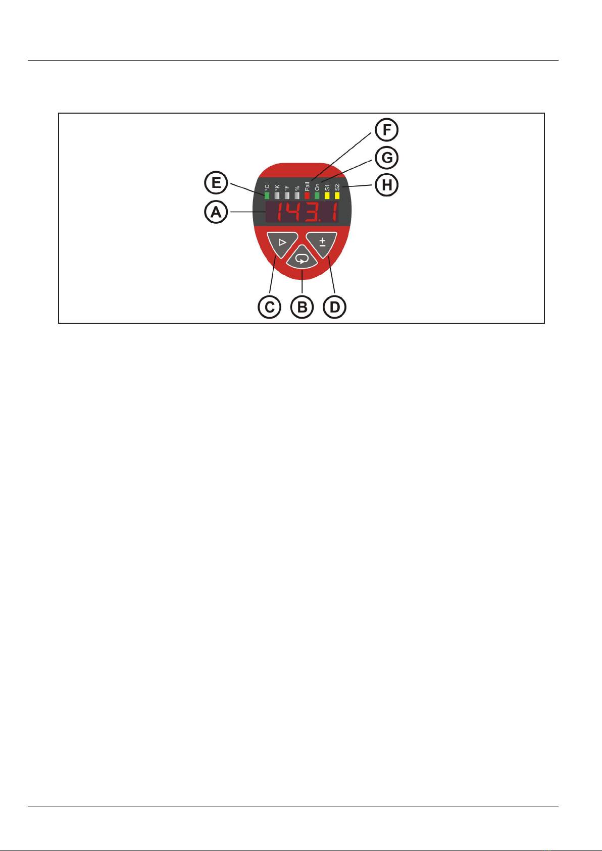
5.1 Operation and display parts
A – LED display
• Display of measuring value and operation menu
B - Key Set
• Access to operation menu
• In the selection menu entering the selected sub menu
• In the set menu applying the new value
C - Key Change
• Change between sub menu
• Cancel value input without applying
• Changeover the counter advance sense of the key +/- from + resp. increasing to - resp.
decreasing.
D - Key +/-
• Value changing by + resp. increasing or - resp. decreasing. The counter advance sense is at
rst always + resp. increasing. Change counter advance sense by the key Change.
• Change setting in a selection menu
E - Unit LED
• Indication unit by green LED
F - Error indication LED
• Indication abnormal behavior by red LED
G - Operation LED
• Indication ready status by green LED
H - Switch condition LED
• Indication of an active switch output by the respective yellow LED
5.2 Function modes
5.2.1 Run mode
The device records the applied physical measurand and proceeds the chosen functions according to
the set parameter.
The active operation is conrmed by the green operation LED.
The measuring value is displayed in the display window.
The chosen unit is marked through the come on of the respective green unit LED.
The current output and the switch outputs and are driven.
A turned on switch output is signaled by the come on of the respective yellow switch condition LED.
The exceedance of the frame specications, abnormal operation conditions and also device
malfunctions are displayed by the red error indication LED.

ACS-CONTROL-SYSTEMGmbHlLauterbachstr.57lD-84307Eggenfeldenlwww.acs-controlsystem.del[email protected]
12
5.2.2 Programming mode
Access to the function menus by the key Set.
• In the switch function menu – password 1903 – all the adjustable parameter and functions are
chosen especially for the use of the device as switch.
• In the transmitter function menu – password 3009 – all the adjustable parameter and
functions are chosen especially for the use of the device as transmitter by using the current
output.
• In the switch point menu – password 1111 – only switch resp. switch back point of the PNP
switch output resp. outputs are accessible for fast adjustment. The function of the switch
outputs can be displayed.
5.3 Switch output S1 / S2
5.3.1 Switch point / Reset switch point
The input values refer to the current measuring value or acc. to display scaling.
The reset switch point must be lower or equal to the switch point.
For both switch functions, there is no default minimum dierence (hysteresis) between switch resp.
switch back point resp. between upper and lower switch point.
If the switch back point is set higher or equal to the switch point resp. the lower switch point is set
higher or equal to the upper switch point the switch back point is set automatically to the switch point
resp. the lower switch point is set automatically to the upper switch point.
The red error indication LED is ashing.
In the error memory service (SEr) / error memory (ErrN) there will be the indication of the
concerning switch output (S1oG or S2oG).
5.3.2 Switch delay time / Reset switch delay time
The activation resp. deactivation of the switch output can be biased with a delay time (resolution
0,1s), to realize simple sequence control system.
5.3.3 Operating mode
The operating mode denes the function direction of the switch output.
Normal Open / NO
• At the output there is no signal, if the switch condition is not fullled.
• At the output there is a signal, if the switch condition is fullled.
Normal Close / NC
• At the output there is a signal, if the switch condition is not fullled.
• At the output there is no signal, if the switch condition is fullled.
5.3.4 Hysteresis function
The hysteresis function realizes a stable switch state, independent from system conditioned signal
uctuations around the adjusted set point.
It can be used for realizing a signal controlled two-position control.
The switch range is determined by input the switch point and switch back point.
The switch output is activated, if the current measuring value exceeds the switch point and if the set
switch point delay time has been expired.
The switch output is deactivated, if the current measuring value exceeds the reset switch point and if
the set reset switch point delay time has been expired.
The actual applied measuring signal can be applied or an arbitrary value can be set as switch resp.
switch back point.

ACS-CONTROL-SYSTEMGmbHlLauterbachstr.57lD-84307Eggenfeldenlwww.acs-controlsystem.del[email protected] 13
5.3.5 Window function
The window function realizes a signal range – acceptance region –, where the switch output is set to a
denitive switch state.
The switch range is determined by input the switch point and switch back point.
The switch output is activated, if the current measuring value is inside the area that is dened by the
switch point and the reset switch point and if the set switch point delay time has been expired.
The switch output is deactivated, if the current measuring value is outside the area that is dened
by the switch point and the reset switch point and if the set reset switch point delay time has been
expired.
The actual applied measuring signal can be applied or an arbitrary value can be set as switch resp.
switch back point.
5.3.6 Error indication function
The switch output S1 can be alternatively used for error indication function. Doing this a switch action
happens, if the output current becomes higher than 20mA resp. lower than 4mA.
5.4 Current output
The nominal values of the current output (4mA/20 mA) refers to the set signal zero and signal end
value.
5.4.1 Error signal
Denes the current output regarding operating range and if errors are registered.
A - O >> 3.9-21mA
B - 3.8mA
C - 22mA
5.4.2 Invert signal
Inverts the current output.
• 4-20mA >> 20-4mA

ACS-CONTROL-SYSTEMGmbHlLauterbachstr.57lD-84307Eggenfeldenlwww.acs-controlsystem.del[email protected]
14
5.5 Self-supervising function
5.5.1 Drift monitoring function
The drift monitoring function is only adjustable at devices with option self-supervising.
Each sensor element that is used for the recording of temperatures has the unavoidable characteristic
a specic behavior concerning long term drift and ageing.
This behavior is very similar if not identically at physically equal-type sensor elements like e.g.
multiple resistive sensors Pt100.
At physically dierent sensor elements like resistive sensors Pt100 and semiconductor sensors or also
NTC however these characteristics are serious dierent.
In the tip of the sensor tube are two physically dierent sensor elements mounted thermal coupled.
For the realizing of a reliable drift supervising a dierent drift behavior of the two sensor elements is
necessary.
Therefore e.g. not two resistive sensors Pt100 are uses, but only one resistive sensor element Pt100
and a semiconductor sensor element.
Under nominal conditions the temperature measuring values, which are recorded by the sensor
elements and transmitted to the processor are identically. Because of the not exactly identical position
of both sensor elements within the sensor tube, the installation position of the sensor tube and the
present process conditions temperature dierences of up to ±0,1K can occur, already at a new device.
This does not aect the function of the drift supervision concerning ageing.
Because of the use of two physically dierent sensor elements it is guaranteed, that the ageing
conditioned characteristic drift of both sensor elements is dierent. At the occurring of an ageing
conditioned characteristic drift in one or also in both sensor elements the dierence between the
temperature measuring values of both sensor elements increases.
The detected dierence between the temperature measuring values is compared with the set drift
response value (drAL) by the processor.
If the temperature dierence between the temperature measuring values transgresses the set drift
response value (drAL), the drift alarm will be registered in the error memory (ErrN), the red error
indication LED starts ashing and the switch output 1, if congured for error function, will be activated
corresponding to the settings in normally open or normally closed function.
The display and the current output generate furthermore a temperature proportional signal, referring
to the temperature measuring value of the primary sensor element, the resistive sensor Pt100. The
switch outputs, which are congured for normal function, refers also to this temperature measuring
values.
Because of the dierent response time of the two sensor elements, at fast and strong temperature
uctuations in the measured medium, e.g. at lling a hot medium in a cold container, it can come to
short time dierences between the two temperature measuring values that are higher than the set
drift response value (drAL).
A wrong drift alarm would be detected.
For the compensation of such wrong behaviors a drift delay time (drd) can be set.
Due to this a drift alarm will only be detected, if after the transgression of the drift response value
(drAL) and after the set drift delay time (drd) the set drift response value (drAL) is already
transgressed.
5.5.2 Redundancy function
The redundancy function is only adjustable at devices with option self-supervising.
The display, the switching output resp. outputs and the current output refers principally to the
temperature measuring value of the primary sensor element, the resistive sensor Pt100.
In the case of a short circuit or a wire break of the primary sensor element, the resistive sensor Pt100
there is the possibility to continue the measurement automatically with the secondary sensor element,
the semiconductor sensor.
The display, the switching output resp. outputs and the current output refers now to the temperature
measuring value of the secondary sensor element, the semiconductor sensor.
A drift monitoring is not possible in the case of the failure of one of the two sensor elements.
The behavior of the temperature switch in the case of the failure of the primary sensor Pt100 resp. the
activation of the redundancy function is made by the parameter (drb).

ACS-CONTROL-SYSTEMGmbHlLauterbachstr.57lD-84307Eggenfeldenlwww.acs-controlsystem.del[email protected] 15
5.6 Menu structure
5.6.1 Menu structure switch function - password 1903

ACS-CONTROL-SYSTEMGmbHlLauterbachstr.57lD-84307Eggenfeldenlwww.acs-controlsystem.del[email protected]
16
5.6.2 Menu structure transmitter function - password 3009

ACS-CONTROL-SYSTEMGmbHlLauterbachstr.57lD-84307Eggenfeldenlwww.acs-controlsystem.del[email protected] 17
5.6.3 Menu structure switch point - password 1111

ACS-CONTROL-SYSTEMGmbHlLauterbachstr.57lD-84307Eggenfeldenlwww.acs-controlsystem.del[email protected]
18
5.7 Parameter overview
Menu group Function Input Description
codE 3009 Password input for the access to the transmitter function menu
1903 Password input for the access to the switch function menu
1111 Password input for the access to the switch point menu
Menu group Function Input Description
diSP DISPLAY – includes all parameters concerning the display
AnSi norA View normal
GEdA View rotated by 180°
Unit C Unit °C
HUnit °K
FUnit °F
SPoN NA Display measuring value - the actual measuring value is shown in the display
SPA Display switch value - the upper limit value of the switch point 1 is shown in the display
dEA don Display indication on – measurement value and status LED are indicated
doFF Display indication o – measurement value and unit LED are deactivated in the run mode.
The operation, error and switch condition indicator LED are still in process.
When accessing the password input by simultaneous pushing the two operation keys +/- and >
for three seconds, the complete display is switched on again.
Menu group Function Input Description
SP1 Switch output 1 – includes all parameters concerning the switch output 1
SP_1 NSiG Adjustment with applied signal – The actual applied temperature value is captured as switch
point resp. upper switch point
oSiG Adjustment without applied signal – The actual switch point / upper switch point is shown in
the display and can now be adjusted by the operation keys +/- and >.
rSP1 NSiG Adjustment with applied signal – The actual applied temperature value is captured as switch
back point resp. lower switch point
oSig Adjustment without applied signal – The actual switch back point / lower switch point is shown
in the display and can now be adjusted by the operation keys +/- and >.
Fc_1 HF_1 The switch output 1 operates in hysteresis function with switch point and switch back point
FF_1 The switch output 1 operates in window function with lower and upper switch point
Func norF Normal function – The switch output 1 operates in hysteresis or in window function
ErrF Error indication function – The switch output 1 operates in error indication function for the
current output. At underrun of 4mA resp. at exceedance of 20mA, the switch output 1 is
activated depending on the settings as closed-circuit or as open-circuit.
nonc no The switch output 1 operates in open-circuit principle resp. – no normally open
nc The switch output 1 operates in closed-circuit principle resp. – nc normally closed
dSP1 Switch delay time for switch point / upper switch point of switching output 1.
The switching output 1 is only activated, if after the entrance of the switch condition and after
the set switch delay time the temperature signal already fullls the switch conditions. By this
e.g. temperature uctuations can be eliminated.
The adjustment range is 0...99 seconds, in steps of 0,1 seconds
drP1 Switch delay time for switch back point / lower switch point of switching output 1.
The switch output 1 is only activated, if after the entrance of the switch back condition
and after the set switch delay time the temperature signal already fullls the switch back
conditions. By this e.g. temperature uctuations can be eliminated.
The adjustment range is 0...99 seconds, in steps of 0,1 seconds
SiN1 AuS1 Simulation – the switch output 1 is deactivated
Ein1 Simulation – the switch output 1 is activated

ACS-CONTROL-SYSTEMGmbHlLauterbachstr.57lD-84307Eggenfeldenlwww.acs-controlsystem.del[email protected] 19
Menu group Function Input Description
SP2 Switch output 2 – includes all parameters concerning the switch output 2
SP_2 NSiG Adjustment with applied signal – The actual applied temperature value is captured as switch
point resp. upper switch point
oSiG Adjustment without applied signal – The actual switch point / upper switch point is shown in
the display and can now be adjusted by the operation keys +/- and >.
rSP2 NSiG Adjustment with applied signal – The actual applied temperature value is captured as switch
back point resp. lower switch point
oSig Adjustment without applied signal – The actual switch back point / lower switch point is shown
in the display and can now be adjusted by the operation keys +/- and >.
Fc_2 HF_2 The switch output 2 operates in hysteresis function with switch point and switch back point
FF_2 The switch output 2 operates in window function with lower and upper switch point
nonc no The switch output 2 operates in open-circuit principle resp. – no normally open
nc The switch output 2 operates in closed-circuit principle resp. – nc normally closed
dSP2 Switch delay time for switch point / upper switch point of switching output 2.
The switch output 2 is only activated, if after the entrance of the switch condition and after the
set switch delay time the temperature signal already fullls the switch conditions. By this e.g.
temperature uctuations can be eliminated.
The adjustment range is 0...99 seconds, in steps of 0,1 seconds
drP2 Switch delay time for switch back point / lower switch point of switching output 2.
The switch output 2 is only activated, if after the entrance of the switch back condition
and after the set switch delay time the temperature signal already fullls the switch back
conditions. By this e.g. temperature uctuations can be eliminated.
The adjustment range is 0...99 seconds, in steps of 0,1 seconds
SiN2 AuS2 Simulation – the switch output 2 is deactivated
Ein2 Simulation – the switch output 2 is activated
Menu group Function Input Description
AbGL Adjustment – includes all parameters concerning the temperature adjustment
2Ero NSiG Adjustment lower temperature reference value with applied signal
- The actual applied temperature value is captured as lower temperature reference value.
- The output current of 4mA, that can be adjusted by the control keys +/- and > arbitrarily, is
assigned to this temperature reference value. Adjustment range 3,9mA to 21mA.
- If the adjusted measuring range is lower than 25% of the nominal measuring range, the
change will be refused and the display shows EEEE.
- An already set oset will be regarded at the adjustment.
oSiG Adjustment lower temperature reference value without applied signal
- The freely adjustable pressure value, in the set unit - Unit-, is captured as lower temperature
reference value.
- The lower output current end value, 4mA, refers to this pressure reference value.
- The measuring span cannot be adjusted lower than 25% of the nominal measuring range.
- An already set oset will be regarded at the adjustment.
SpAn NSiG Adjustment upper temperature reference value with applied signal
- The actual applied temperature value is captured as upper temperature reference value.
- The output current of 20mA, that can be adjusted by the control keys +/- and > arbitrarily, is
assigned to this temperature reference value. Adjustment range 3,9mA to 21mA.
- If the adjusted measuring range is lower than 25% of the nominal measuring range, the
change will be refused and the display shows EEEE.
- An already set oset will be regarded at the adjustment.
oSiG Adjustment upper pressure reference value without applied signal
- The freely adjustable pressure value, in the set unit - Unit-, is captured as upper pressure
reference value.
- The upper output current end value, 20mA, refers to this pressure reference value.
- The measuring span cannot be adjusted lower than 25% of the nominal measuring range.
- An already set oset will be regarded at the adjustment.
oFFS The temperature measuring value can be shift by an oset of up to 25°C.
This can be necessary in unfavorable installation situations or at considerable temperature
dierences between medium and measurement position.
inS AUSA The output current corresponds to the assignment of the adjustment >> 4...20mA
EinA The output current behaves inverted to the assignment of the adjustment >> 20...4mA
SiNA The current output can be arbitrarily simulated in the whole utilizable range from 3,8mA to
22mA by using the operation keys +/- and >.
ErrS oFF The current output operates linear in the range from 3,9mA to 21,0mA. A current output
besides this limits is not possible, the end values are kept at exceedance. An error current
output at underrun resp. exceedance does not occur.
FS38 The current output operates linear in the range from 4,0mA to 20,0mA. At underrun of 4mA
resp. at exceedance of 20mA a constant current of 3,8mA is generated.
FS22 The current output operates linear in the range from 4,0mA to 20,0mA. At underrun of 4mA
resp. at exceedance of 20mA a constant current of 22mA is generated.

ACS-CONTROL-SYSTEMGmbHlLauterbachstr.57lD-84307Eggenfeldenlwww.acs-controlsystem.del[email protected]
20
Menu group Function Input Description
SEr Service – includes all parameters concerning service purposes
t_F Input of the system damping for reassuring of cyclic uctuating temperature signals.
The adjustment range is 0...40 seconds, in steps of 0,1 seconds
ErrN noE No error recorded in the error memory.
brch A wire break at the internal connections of the sensor element has been detected.
Hur A short circuit at the internal connections of the sensor element has been detected
FLAS An error in the internal nonvolatile data memory (ash) has been detected.
Nunt The lower measuring range limit value (display zero) has been underrun.
NuEb The upper measuring range limit value (display span) has been exceeded.
Aunt The lower limit value of the current output (3,9mA) has been underrun.
AuEb The upper limit value of the current output (21mA) has been exceeded.
S1oG The switch back point rSP1 of the switch output 1 has been adjusted higher or equal to the
switch point SP_1.
S2oG The switch back point rSP2 of the switch output 2 has been adjusted higher or equal to the
switch point SP_2.
S1oP The switch output 1 is not activated, although it should be.
S2oP The switch output 2 is not activated, although it should be.
rAN An error in the internal working memory (RAM) has been detected.
drFt The exceedance of the set drift threshold value has been detected.
NA Maximum value memory – display of the highest measured temperature value.
Nin Minimum value memory – display of the lowest measured temperature value.
drAL A drift alarm is only made, if the set drift threshold value, the dierence between the
temperature measuring values of the two sensor elements, has been exceeded.
The adjustment range is 0,2...5 K, in steps of 0,1K.
drd
A drift alarm is only made, if after the exceedance of the drift threshold value and after the set
drift delay time the drift threshold value has been already exceeded.
By this, e.g. the dierent response time of the two sensor elements at temperature deviations
can be compensated.
The adjustment range is 0...300 seconds, in steps of 1 second.
drb
AUS The redundancy function is deactivated
Ein The redundancy function is activated. At the failure of the sensor element Pt100 the measuring
is continued with the semiconductor sensor element.
301 Version number of the installed rmware
FrES Factory Reset – reset of all parameters to factory values
SPEi Storage – loss protected storage of all parameters
Menu group Function Input Description
Switch point menu
SP_1 The current switch point / upper switch point of switch output 1is shown in the display and can
be adjusted by the control keys +/- and >.
rSP1 The current switch back point / lower switch point of switch output 1 is shown in the display
and can be adjusted by the control keys +/- and >.
SP_2 The current switch point / upper switch point of switch output 2 is shown in the display and can
be adjusted by the control keys +/- and >.
rSP2 The current switch back point / lower switch point of switch output 2 is shown in the display
and can be adjusted by the control keys +/- and >.
Fc_1 The set switch function of the switch output 1 is displayed. This setting cannot be changed
here.
HFno The switch output 1 operates in hysteresis function with working principle normal open
HFnc The switch output 1 operates in hysteresis function with working principle normal closed
FFno The switch output 1 operates in window function with working principle normal open
FFnc The switch output 1 operates in window function with working principle normal closed
Fc_2 The set switch function of the switch output 2 is displayed. This setting cannot be changed
here.
HFno The switch output 2 operates in hysteresis function with working principle normal open
HFnc The switch output 2 operates in hysteresis function with working principle normal closed
FFno The switch output 2 operates in window function with working principle normal open
FFnc The switch output 2 operates in window function with working principle normal closed
Table of contents


