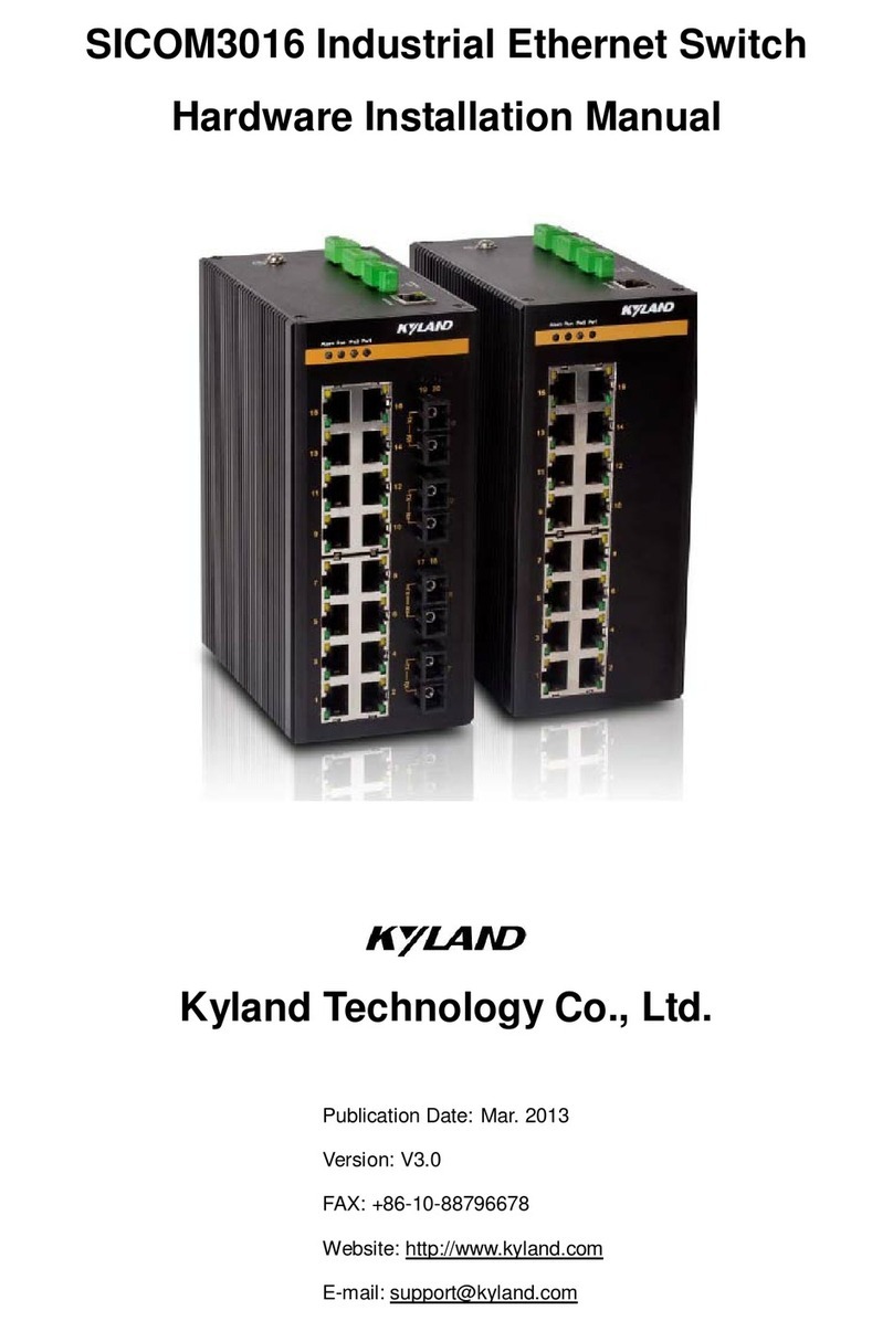
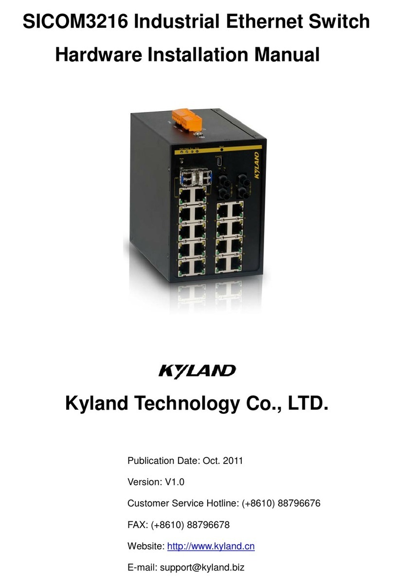
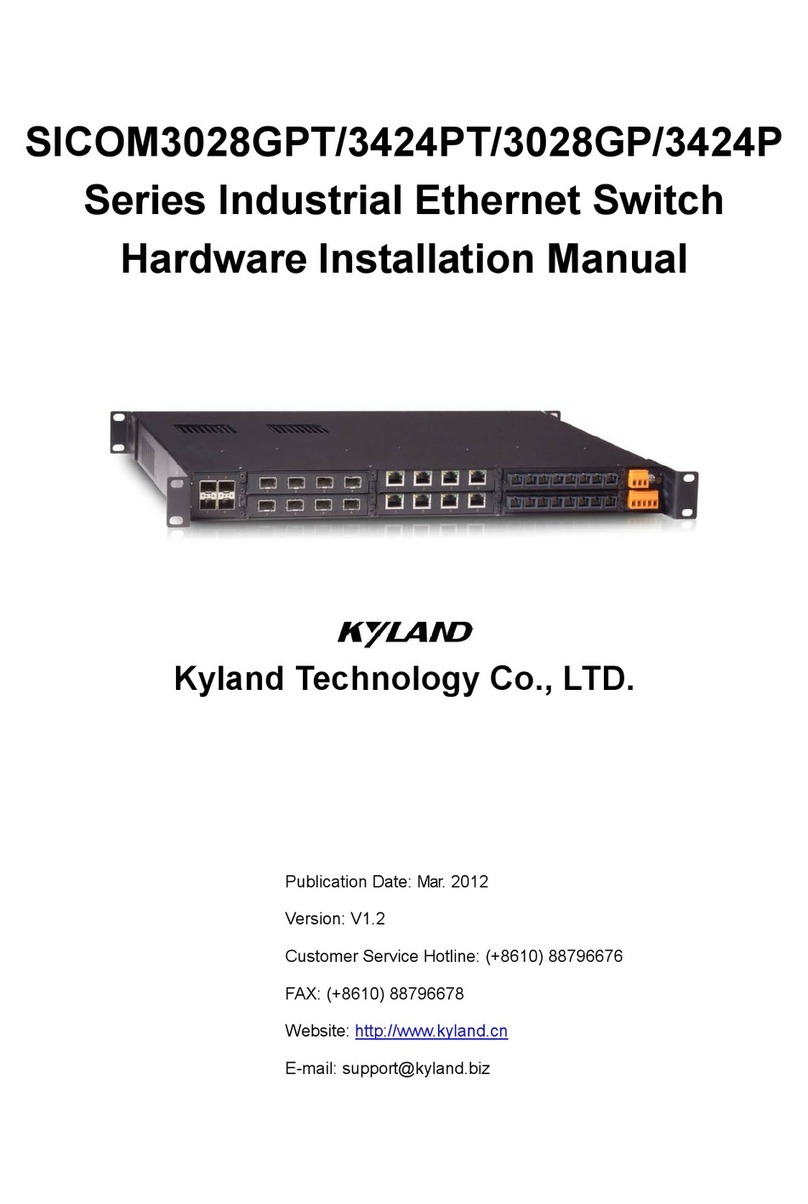
KYLAND Technology SICOM Series Instruction sheet

1
SICOM Series Industrial Ethernet Switch
Command Line Configuration Manual
Copyright © 2009 KYLAND Technology CO., LTD.
All rights reserved.
No part of this documentation may be excerpted, reproduced, translated, annotated or
duplicated, in any form or by any means without the prior written permission of KYLAND
Corporation.
Publisher: KYLAND Technology CO., LTD.
Address: Chongxin Creative Building, Shixing East Road 18#, Shijingshan
District, Beijing, China
Website: http://www.kyland.cn
Postcode: 100041
Tel: (+8610)88796676
FAX: (+8610)88796678
E-mail: sales@kyland.cn
Version: V1, May. 2009
No.:27030042-10

SICOM Series CLI Command Manual
2
CONTENTS
Chapter 1 CLI Command Introduction ..............................................................................................6
1.1 Login the Switch ..................................................................................................................6
1.1.1 Command Line .........................................................................................................6
1.1.2 Command Grammar.................................................................................................6
1.1.3 Grammar Help..........................................................................................................7
1.1.4 Complete Command by Grammar Help...................................................................7
1.1.5 Symbol in Command ................................................................................................8
1.1.6 Types of Command Parameters ...............................................................................8
1.1.7 Command Abbreviation ...........................................................................................8
1.1.8 History Command.....................................................................................................9
1.2 Common Commands...........................................................................................................9
1.2.1 Mode Configuration .................................................................................................9
1.2.2 Password Configuration .........................................................................................10
1.2.3 Showing version .....................................................................................................10
1.2.4 Showing device running function...........................................................................10
1.2.5 Showing device configuration information ............................................................10
1.2.6 Save configuration and restore default configuration...........................................11
1.3 Switch Management Methods..........................................................................................11
1.4 Console Management .......................................................................................................11
Chapter 2 Port Configuration ..........................................................................................................12
2.1 Port Configuration Overview.............................................................................................12
2.2 Configure Port Functions...................................................................................................13
2.2.1 Enter port configuration menu ..............................................................................13
2.2.2 Enable/disable port................................................................................................13
2.2.3 Auto- negotiation configuration.............................................................................13
2.2.4 Port rate configuration ...........................................................................................13
2.2.5 Port duplex configuration.......................................................................................14
2.2.6 Port flow control configuration..............................................................................14
2.3 Port mirroring configuration .............................................................................................14
2.3.1 Enable/disable port mirroring................................................................................14
2.3.2 Mirroring port configuration..................................................................................14
2.4 ACL configuration ..............................................................................................................15
2.5 Configure query function ..................................................................................................15
2.5.1 ACL configuration query.........................................................................................15
2.5.2 Port statistics query................................................................................................15
2.5.3 Port mirroring query ..............................................................................................15
2.5.4 Port configuration query ........................................................................................16
Chapter 3 Port speed limitation......................................................................................................17
3.1 Overview of port speed limitation function......................................................................17
3.2 Setting port rate mask (types of message)........................................................................18
3.3 Port rate configuration ......................................................................................................18
3.4 Showing a port’s speed limitation.....................................................................................19

SICOM Series CLI Command Manual
3
3.5 Showing overall port speed limitation configuration........................................................19
Chapter 4 VLAN Function Configuration .........................................................................................20
4.1 VLAN function introduction ..............................................................................................20
4.2 VLAN function configuration.............................................................................................21
4.2.1 VLAN port configuration.........................................................................................21
4.2.2 Adding VLAN port...................................................................................................21
4.2.3 Delete port from VLAN...........................................................................................21
4.2.4 Adding the name of VLAN port ..............................................................................21
4.2.5 Back to the upper list .............................................................................................22
4.2.6 Back to the main menu ..........................................................................................22
4.3 PVLAN function configuration...........................................................................................22
4.3.1 Adding PVLAN ........................................................................................................22
4.3.2 Delete PVLAN .........................................................................................................22
4.3.3 PVLAN configuration example................................................................................22
Chapter 5 TRUNK function configuration........................................................................................25
5.1 Brief introduction of TRUNK function ...............................................................................25
5.2 TRUNK function configuration ..........................................................................................25
5.2.1 Trunk port configuration ........................................................................................25
5.2.2 Adding Trunk port ..................................................................................................25
5.2.3 Delete port from Trunk ports .................................................................................25
5.2.4 Back to main menu ................................................................................................26
5.2.5 Back to upper menu...............................................................................................26
Chapter 6 QoS Configuration ..........................................................................................................27
6.1 QoS overview ....................................................................................................................27
6.2 QoS configuration..............................................................................................................27
6.2.1 Enable/disable QoS ................................................................................................27
6.2.2 QOS scheduling mode configuration......................................................................28
6.2.3 Scheduling strategies configuration .......................................................................28
6.2.4 Priority weight ratio configuration .........................................................................29
6.2.5 VLAN priority mapping configuration.....................................................................29
6.2.6 TOS priority mapping configuration .......................................................................30
6.2.7 DSCP priority mapping configuration.....................................................................30
6.2.8 Showing QoS configuration ....................................................................................30
Chapter 7 IGMP Snooping Configuration........................................................................................31
7.1 IGMP Snooping Overview .................................................................................................31
7.2 IGMP Snooping Configuration...........................................................................................31
7.2.1 Configure IGMP Snooping auto-query function.....................................................31
7.2.2 Enable/disable IGMP Snooping..............................................................................32
7.2.3 Showing the information of IGMP Snooping multicast group members ...............32
Chapter 8 DT-Ring Protocol configuration ......................................................................................33
8.1 Brief introduction of DT-Ring protocol family ...................................................................33
8.2 Introduction of DT-Ring.....................................................................................................33
8.3 DT-Ring configuration........................................................................................................34
8.3.1 Create / Delete DT-Ring domain ............................................................................34

SICOM Series CLI Command Manual
4
8.3.2 Create/Delete the ring ports ..................................................................................34
8.3.3 DT-Ring protocol Enable/Disable ...........................................................................35
8.3.4 Display the status of the DT-Ring domain..............................................................35
Chapter 9 DT-VLAN protocol configuration.....................................................................................36
9.1 Introduction of DT-VLAN protocol.....................................................................................36
9.2 DT-VLAN configuration......................................................................................................37
9.2.1 Change the setting of DT-Ring................................................................................37
9.2.2 Create/Delete DT-Ring domain ..............................................................................37
9.2.3 Create/Delete ring ports ........................................................................................37
9.2.4 Create/Delete VLAN ...............................................................................................38
9.2.5 Enable/Disable DT-Ring Protocol ...........................................................................38
9.2.6 Display the status of the DT-Ring domain..............................................................38
Chapter 10 DT-Ring+ configuration.................................................................................................39
10.1 Introduction of DT-Ring+.................................................................................................39
10.2 DT-Ring+ Configuration ...................................................................................................39
10.2.1 Enable/Disable DT-Ring+......................................................................................39
10.2.2 Create/Delete backup ports .................................................................................40
10.2.3 Display the status of DT-Ring+ .............................................................................40
Chapter 11 RSTP configuration .......................................................................................................41
11.1 Introduction of RSTP .......................................................................................................41
11.2 RSTP configuration ..........................................................................................................41
11.2.1 RSTP bridge node .................................................................................................41
11,2,2 RSTP port configuration .......................................................................................43
11.2.3 Display RSTP status...............................................................................................43
Chapter 12 SNMP Configuration .....................................................................................................45
12.1 Introduction of SNMP .....................................................................................................45
12.2 SNMP configuration ........................................................................................................45
12.2.1 Enable/Disable SNMP...........................................................................................45
12.2.2 Read/Write community name..............................................................................46
12.2.3 Trap IP address configuration...............................................................................46
12.2.4 Request/Trap port number ..................................................................................46
12.2.5 Setting the number of EMS management stations ..............................................47
12.2.6 Enable/Disable Trap .............................................................................................47
12.3 Display SNMP status........................................................................................................47
Chapter 13 RMON configuration.....................................................................................................48
13.1 Introduction of RMON.....................................................................................................48
13.2 RMON configuration .......................................................................................................48
13.2.1 RMON operating parameters setting ...................................................................48
13.2.2 Display RMON status............................................................................................50
Chapter 14 ALARM management configuration .............................................................................54
14.1 Introduction of ALARM management module................................................................54
14.2 ALARM configuration ......................................................................................................54
14.2.1 Port link down enable/disable .............................................................................54
14.2.2 Address conflict detect enable/disable................................................................55

SICOM Series CLI Command Manual
5
14.2.3 DT-Ring ring open alarm enable/disable..............................................................55
14.3 Display alarm status information ....................................................................................55
SICOM Series CLI Command Manual
6
Chapter 1 CLI Command Introduction
This chapter mainly introduces how to configure SICOM series Industrial Ethernet Switch by
CLI command and the instructions of command set.
1.1 Login the Switch
1.1.1 Command Line
User can log in command line via serial port or Telnet.
To log in via serial port, connecting serial ports between PC and switch is required. See more
details of serial port configuration in Chapter 1.4
Start up the switch, select the serial port, and type the key “Enter”; you can see the prompt in
the serial port. At default state, the prompt is “kyland>”.
Note:
If you want to keep the change after the switch reboot, please use the “save” command after
your configuration. See more details in Common Command Description。
1.1.2 Command Grammar
To use the command line interface (CLI) as the following steps:
1. Type “Enable” after you enter CLI and command prompt pop up, enter command line
mode, there will be a command prompt “kyland#”.
2. Type the command name. If the command doesn’t contain any parameter that need to be
input by user, skip to step three. If the command contains parameters that require user to
input, please continue the following steps: If the command need a parameter, please input
the parameter, and key words might be needed when you typing the parameter.
Command parameters specify the type of parameters. The types of parameter might be
values in a certain range, string or IP address. The key word is the object that the
command work to. If the command requires more than one parameters, please type the
key words and parameters one by one with the command instructions until <cr> appears.
3. After input the full command, type the key “Enter”

SICOM Series CLI Command Manual
7
1.1.3 Grammar Help
The grammar help is integrated in command line interface. If not sure about the grammar,
please type the first part of command you know, followed with “?” or type the key “Space”
and “ ?” The command line will automatically display the possible command list of the rest
part. Users can choose the right one and finish the rest part until the command line shows
“<cr>”. Then type the key “Enter” to finish.
1.1.4 Complete Command by Grammar Help
When you type key of “Tab”, management software can complete command. When you enter
a part of command and type key of “Tab”, the possible commands will be listed if the
matching commands are more than one; if only one matching command. the command line
will automatically complete the rest part of the command and move the cursor to the end
EX:
1. Type the command:
KYLAND#show
2. Type key of “Space” and “Tab”, you can see:
broadcaontrol
Broadcontrol
clock
Display the system clock
config
System configuration
fdb
Fdb
history
Display the session command history
igmp
Igmp snooping protocol
interface
Interface status and configuration
manager
Management station status
memory
System memory statistics information
dt-ring
DT-Ring protocol
rstp
Rapid spanning tree protocol
running-config
Current operating configuration
snmp
SNMP status
switch
Show switch status
telnet
Telnet configure information
timer
show timer message
trunk
Show vlan information
uptime
Display the system uptime
version
System hardware and software status
vlan
Show vlan information
Above information are the possible commands after the “show” command. User can
select the correct command. If the command is long, user can also type the key “Tab” to
finish the command.

SICOM Series CLI Command Manual
8
1.1.5 Symbol in Command
In the management software, only one symbol “< >” is supported. It means a parameter is
required in this part of the command.
For example: dt-ring new <1-32> domain <1-32> master
1.1.6 Types of Command Parameters
Normally the command in an angle bracket “< >” is command parameters. There are four
types of command parameters in this series switches.
A range of number:
When the numbers in “< >” is connected by a short line, which means the parameter is a
number between this range.
For example: <1-255> means user can input any number in this range (more than or equal 1,
less than or equal 255), such as “2”.
IP address:
The “A.B.C.D” in angle bracket means the parameter is IP address. User must input a valid IP
address.
For example: 192.168.0.1
String:
If the content in “< >” is not above two forms, a string or a hexadecimal number is required.
Users can input a “?” at this place to know the detail parameter description. For example:
<macaddr> means the required parameter is a hex MAC address, Such as 005023344325 is a
Mac address. And <name> requires a string to be the subject’s name.
1.1.7 Command Abbreviation
Command abbreviation is that users only input the first several letters of the command word
or the key word. As long as these letters don’t cause ambiguity, switch is able to recognize
that command, and user can type the key “Enter” to run that command. But if the required
parameter is VLAN’s name, etc, it need to be fully input. In the below example, the VLAN’s
name is “market”.
Example, adding port 1 to “market” with untagged form:
In VLAN, typing the following command:
KYLAND>
KYLAND>enable
KYLAND#config terminal
KYLAND(config)#

SICOM Series CLI Command Manual
9
KYLAND(config)#vlan 2
KYLAND(config-vlan2)#description market
KYLAND(config-vlan2)#add port 1 untag priority 0
This command line can be abbreviated to:
KYLAND>
KYLAND>ena
KYLAND#con ter
KYLAND(config)#
KYLAND(config)#vlan 2
KYLAND(config-vlan2)#desc market
KYLAND(config-vlan2)#add port 1 un pr 0
Above two kinds of commands have same functions.
Note:
When using command abbreviation function, user must input enough letters to avoid
ambiguity.
1.1.8 History Command
The software can keep the record of the latest 10 history commands user used.
To show history command list, use the following command:
Kyland#show history
1.2 Common Commands
This part mainly describes several common commands, and some specially used commands
will be discussed in other chapters.
1.2.1 Mode Configuration
Command lines provide two types of modes: one is Read Only mode, the other is
Configuration Mode. At Read Only mode, user can only read a part of system configuration
information. At Configuration Mode, user can read and configure all system configuration
information. At configuration mode, you can use some commands to enter certain protocols’
independent configuration mode, such as: “KYLAND#” is interface configuration mode.
At Read Only mode, the prompt ends with “>” i.e. “KYLAND>”
At Configuring mode, the prompt ends with “#” i.e. “KYLAND#”

SICOM Series CLI Command Manual
10
Enable configuration mode
Enable configuration mode at Read Only mode, using this command:
KYLAND>enable
Type the key “Enter”, and password is required:
Password:
With correct password, enter the Configuration Mode
Disable Configuration Mode, using the following command:
KYLAND#disable
1.2.2 Password Configuration
SICOM series industrial Ethernet switch support the password checking function for
command line and Telnet
Password configuration
KYLAND(config)# enable password <1-20>
1.2.3 Showing version
To show software version, using the command:
KYLAND#show version
Industry Ethernet Switch Software
Version: 1.2.3
Compiled time: 2009-01-13 18:14
BootRomVersion: 1.0.20
Compiled time: 2008-05-15 14:18
HardWare:SICOM-3024
1.2.4 Showing device running function
At Configuration Mode, to display system running function, using the command:
KYLAND#show running-config
1.2.5 Showing device configuration information
At configuration mode, using below command to see the system configuration
KYLAND#show config

SICOM Series CLI Command Manual
11
1.2.6 Save configuration and restore default configuration
To save current configurations
KYLAND# save
To restore default configuration
KYLAND# load default
Note:
If users want to reset switch’s start configuration information, use this command to delete
former configuration.
1.3 Switch Management Methods
SICOM series industrial Ethernet switches are mainly managed by the following methods:
Connecting a terminal (or terminal emulation software) with switch’s Console port
to access switch’s CLI
Using Telnet to manage switch
Using SNMP to manage switch
Using WEB to manage switch
1.4 Console Management
Using Console RJ45 serial port at the front panel of switch to connect with switch’s built-in
CLI interface. For SICOM series switch, the configuration of Console port is as below:
Baud Rate
9600
Bit
8
Parity
None
Stop Bit
1
Flow Control
None
When connecting switch with Console port, VT100 terminal emulation is recommended.
Configuration steps: at hyper terminal interface, open “file” menu, select “attribute”, and click
“configure” at the window, then select VT100 in the list.

SICOM Series CLI Command Manual
12
Chapter 2 Port Configuration
2.1 Port Configuration Overview
The port configuration of SICOM series Industrial Ethernet Switch contains port-related
configuration and the configuration of port-based functions. In the port configuration
commands, user can configure the functions of auto-negotiation, port enable, duplex, flow
control, mirroring, port rate, ACL, etc.
Auto negotiation:
SICOM series Industrial Ethernet Switch supports the auto-negotiation function for ports;
ports with auto-negotiation function can automatically negotiate the communication mode
(duplex state, communication speed, etc) according to the port state in the other end. This
function only work to 10/100M copper port and 1000M fiber or copper port; 100Base-FX
ports do not support auto negotiation and their fixed rate is 100M and the duplex mode is
full duplex.
Flow control:
SICOM series Industrial Ethernet Switch supports 802.3-based port flow control. At full
duplex mode, if the port receives data beyond its limit, the port would transmit flow control
frames so as to prevent the packet loss caused by the rate limit. At the half duplex mode, if
the port receives data beyond its limit, the port would generate the back pressure half duplex
collision detection frames to reduce the transmitting data from the sending end.
Mirroring
The mirroring of SICOM series Industrial Ethernet Switch is port-based mirroring. Its
function is to copy the data at the mirroring port to mirrored port(s) with the purpose of
monitoring mirroring ports, and so on.
ACL:
SICOM series Industrial Ethernet Switch supports Port + MAC-based ACL function with
“accept” and “reject” two modes which can basically guarantee the port security. At the
“accept” mode, only the configured MAC address can pass through switch. At the “reject”
mode, configured MAC address is not allowed to pass through the switch.

SICOM Series CLI Command Manual
13
2.2 Configure Port Functions
2.2.1 Enter port configuration menu
Enter port configuration, using the below command:
KYLAND(config)# int eth <1,24>
Take port 1 as example in the following examples.
2.2.2 Enable/disable port
Enable port
KYLAND(config-if-eth1)# no lock
Disable port
KYLAND(config-if-eth1)# lock
2.2.3 Auto- negotiation configuration
Enable auto-negotiation
KYLAND(config-if-eth1)# auto-negotiation
Disable auto-negotiation
KYLAND(config-if-eth1)# no auto-negotiation
2.2.4 Port rate configuration
Port rate configuration (10M/100M/1000M) makes ports work under the fixed rate.
10M port rate configuration:
KYLAND(config-if-eth1)# speed 10m
100M port rate configuration:
KYLAND(config-if-eth1)# speed 100m
1000M port rate configuration:
KYLAND(config-if-eth1)# speed 1000m
Note:
Do not set 1000M speed to the 10M/100M ports.

SICOM Series CLI Command Manual
14
2.2.5 Port duplex configuration
Full duplex configuration:
KYLAND(config-if-eth1)# duplex
Half duplex configuration:
KYLAND(config-if-eth1)# no duplex
2.2.6 Port flow control configuration
Enable the flow control
KYLAND(config-if-eth1)# flow-control
Disable the flow control:
KYLAND(config-if-eth1)# no flow-control
2.3 Port mirroring configuration
2.3.1 Enable/disable port mirroring
Enable port mirroring
KYLAND(config-if-eth1)# mirror enable
Enable the port mirroring and set this port as mirroring port
Disable port mirroring
KYLAND(config-if-eth1)# mirror disable
2.3.2 Mirroring port configuration
Adding egress mirroring to mirrored ports
KYLAND(config-if-eth1)# mirror add egress port 2
Adding ingress mirroring to mirrored ports
KYLAND(config-if-eth1)# mirror add ingress port 2
Delete egress mirroring from mirrored ports
KYLAND(config-if-eth1)# mirror delete egress port 2
Delete ingress mirroring from mirrored ports

SICOM Series CLI Command Manual
15
KYLAND(config-if-eth1)# mirror delete ingress port 2
2.4 ACL configuration
Setting “accept” mode for port ACL
KYLAND(config-if-eth1)# acl mode accept
Setting “reject” mode for port ACL
KYLAND(config-if-eth1)# acl mode reject
Setting none for port ACL
KYLAND(config-if-eth1)# acl mode none
Adding MAC address for port
KYLAND(config-if-eth1)# acl mac add HH:HH:HH:HH:HH:HH
Delete MAC address for port
KYLAND(config-if-eth1)# acl mac delete HH:HH:HH:HH:HH:HH
2.5 Configure query function
2.5.1 ACL configuration query
Query of ACL port mode configuration
KYLAND(config-if-eth1)# show acl mode
Query of ACL port MAC address configuration
KYLAND(config-if-eth1)# show acl mac
2.5.2 Port statistics query
KYLAND(config-if-eth1)# show stats
2.5.3 Port mirroring query
KYLAND# show mirror

SICOM Series CLI Command Manual
16
2.5.4 Port configuration query
KYLAND# show int eth <1, 24>
The parameter <1, 24>: Port ID.

SICOM Series CLI Command Manual
17
Chapter 3 Port speed limitation
3.1 Overview of port speed limitation function
SICOM series Industrial Ethernet Switch supports port transmitting rate limitation, services
limitation and broadcast limitation, which all belong to the traffic limitation function.
Support max 26 ports’ speed limitation at the same time.
Support user typing specific limit value
Speed limitation range
The minimum limitation value: 64Kbps;
the max limitation value: 100*100Kbps (100M port)
Speed limitation accuracy
Different accuracy in different speed limitation range, see more detail in the below table:
Users’ setting range
Step value
Error range
Example
64K~1.792M
64K
Between -32K~32K
Input value: 65K
Actual value:64K
Input value:127K
Actual value: 128K
2M~100M
1M
Between
-0.5M~0.5M
Input value:2.3M
Actual value;2M
Input value: 2.8M
Actual value:3M
Control Interface: support the speed limitation control by CONSOLE port, Telnet and WEB.
Limitation mode:
Speed limitation is divided into two groups, group 1 and group 2. The message firstly access
group 1 which is specialized in the limitation of service messages and is fixed to all ports.
Group 2 is used to do limitation to other messages and it is also fixed to all ports.
Default configuration:
Service messages: unicast, multicast
Broadcast messages: broadcast, reserved multicast, unknown unicast, unknown multicast.
Support separated limitation of service messages and broadcast messages
Support overall speed limitation for transmitting messages.
Support showing all ports’ speed limitation configuration
Support showing each port’s speed limitation configuration

SICOM Series CLI Command Manual
18
3.2 Setting port rate mask (types of message)
Ingress direction
Configure the types of message speed limitation
SWITCH(config)#port-rate ingress [service|broadcast] [add|delete]
<0,4>
The parameter <0, 4> 0: unicast, 1: multicast, 2: broadcast, 3: reserved multicast, 4:
Destination Lookup Fail (DLF) (including unknown unicast, unknown multicast)
Showing the types of message speed limitation in ingress direction
SWITCH(config)#port-rate ingress show
Showing overall port speed limitation configuration
SWITCH#show port-rate
3.3 Port rate configuration
Ingress direction
Service/broadcast limitation configuration
SWITCH(config-if-eth x)#port-rate ingress [service|broadcast]
rate <64-1000000>
The parameter <64-1000000> is the parameter in speed limitation range, x means the
ID of speed limitation port
Disable service/broadcast limitation
SWITCH(config-if-eth x)#port-rate ingress [service|broadcast]
disable
Egress direction
Port transmitting speed limitation configuration
SWITCH(config-if-eth x)#port-rate egress rate <64-1000000>
The parameter <64-1000000> is the parameter in speed limitation range, x means ID of
speed limitation port
Disable port transmitting speed limitation
SWITCH(config-if-eth x)#port-rate egress disable
The parameter x means ID of speed limitation port

SICOM Series CLI Command Manual
19
3.4 Showing a port’s speed limitation
SWITCH(config-if-eth x)#show port-rate
The parameter x means the ID of speed limitation port
3.5 Showing overall port speed limitation configuration
SWITCH#show port-rate

SICOM Series CLI Command Manual
20
Chapter 4 VLAN Function Configuration
4.1 VLAN function introduction
VLAN (Virtual Local Area Network) is a broadcast domain formed by a group of terminal
workstations. The hosts ( ports of Industrial Ethernet switch) in the same VLAN are able to
communicate with each other and create a logical working group without considering the
specific wiring. Dividing the corporate network into VLAN segments enhance network
management and network security and control unnecessary data broadcasts.
In a shared network, a physical segment is a broadcast domain, but in a switching network,
broadcast domain can be a virtual network segment formed by a group of MAC addresses. In
this way, the division of working groups breaks down the geographical location restriction in
the shared network and is completely divided by management functions. This grouping
mode is based on the working flow greatly improve the network planning and restructuring
management functions.
The workstations in a same VLAN, whatever they are connected to any switch, the
communication between them is like in standalone hubs. Broadcasts in a VLAN can only be
received by the members of this VLAN and would never be transmitted to other VLAN. This
function greatly controls the broadcast storm. Meanwhile, different VLANs cannot do
communication with each other without router, which enhance the network security in
different company departments. Network administrators can wholly manage the information
sharing in different company departments by configuring routers in different VLANs. Switch
divides VLAN by MAC address of users’ workstations, so user can freely move to work in
corporate network. Wherever they get into the switching network, they can communicate
with other users in VLAN freely.
VLAN might be formed by mixed network equipments, such as 10M Ethernet, 100M Ethernet,
token ring, FDDI, CDDI, etc. and might be workstation, server, hub, etc.
VLAN’s management need complex specialized software which achieve the network VLAN
division, monitoring, etc functions and other expanded management functions by
comprehensive management of users, MAC address, switch port number, VLAN number, etc.
The most common used VLAN division method is based on MAC address. Some other switch
manufacturers provide more VLAN division methods: MAC address, protocol address,
switches port, network application type, and user rights.
When selecting switch, user should pay much attention to the VLAN function and choose the
satisfactory and easy managed switch according to own requirements. At the same time,
users should note that switch VLANs from different manufacturers is mostly not compatible
at present.
Table of contents
Other KYLAND Technology Switch manuals

KYLAND Technology
KYLAND Technology SICOM3028GPT Series Assembly instructions

KYLAND Technology
KYLAND Technology Opal5 series Assembly instructions

KYLAND Technology
KYLAND Technology SICOM1005R-M12 User manual

KYLAND Technology
KYLAND Technology KIEN1005 Assembly instructions

KYLAND Technology
KYLAND Technology Aquam8512 User manual

KYLAND Technology
KYLAND Technology SICOM3016 Series Assembly instructions

KYLAND Technology
KYLAND Technology SICOM3009A Series User manual

KYLAND Technology
KYLAND Technology SICOM3028GPT Series Assembly instructions

KYLAND Technology
KYLAND Technology SICOM6000A Assembly instructions

KYLAND Technology
KYLAND Technology SICOM3216-16T Assembly instructions