10770
Introduction
General description ______________________________________________________________1
Features ________________________________________________________________________2
Package contents ________________________________________________________________2
Hardware installation
Installation procedure_____________________________________________________________2
Standalone configuration __________________________________________________________2
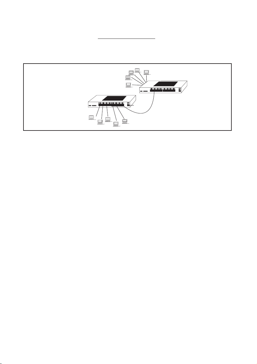
Multi-level configurations, cascading ________________________________________________3
Trouble shooting __________________________________________________3
Specifications _____________________________________________________3
Introduction
General Description
The RS Fast Ethernet Hubs are designed to bring 100Mbps Ethernet to the workplace, in offices and
labs, in compact and affordable packages. providing four Fast Ethernet ports, the FE4 Hub enables
power users to access Fast Ethernet. The eight-port FE8 Hub provides the capacity for small
workgroups to connect to Fast Ethernet.
Both Hubs have a push-button up-link switch (operates on port 4 for the FE4 and port 8 for the FE8).
This link-up switch enables cascading when the button is pressed into the crossover position.
Alternatively, when the button is “un-pressed,” the port operates as a normal node-connection port.
With the up-linkport connected to a hub, users or workgroups gain greater control over their
applications via “un-pressing” the up-link button, detaching the hub and its connected devices from
the rest of the network. This feature is generally useful in testing applications or instances when
maximum bandwidth is required.
The RS FE4 and FE8 Hubs comply with the IEEE 802.3u standards. Both Hubs can be easily installed.
No DIP switch needs to be set and no software needs to be loaded. Simply connect the power
adaptor to a power source and connect the desired network devices into the RJ-45 ports.
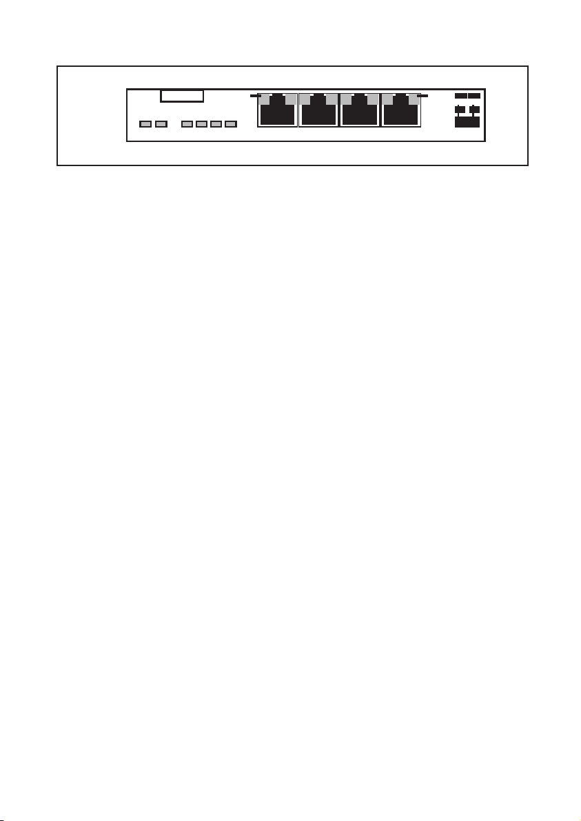
The % utilisation LEDs provides for convenient monitoring of network traffic loading. As traffic levels
increase, more LEDs come on to indicate more network loading in a bar-graph fashion. LINK and RX
LEDs on each port indicate that port is operational or receiving data, respectively. PART (partition)
indicates that port has been partitioned to remove a detected fault. COL (collision) and PWR
(power) LEDs indicate hub status.
The information provided in RS technical literature is believed to be accurate and reliable; however, RS
Components assumes no responsibility for inaccuracies or omissions, or for the use of this information, and all use
of such information shall be entirely at the user’s own risk.
No responsibility is assumed by RS Components for any infringements of patents or other rights of third parties
which may result from its use.
Specifications shown in RS Components technical literature are subject to change without notice.
RS Components, PO Box 99, Corby, Northants, NN17 9RS Telephone: 01536 201234
An Electrocomponents Company © RS Components 1998
4 Port FE4 hub RS stock no. 288-5774
8 Port FE8 hub RS stock no. 288-5780
Issued March 1998 10770
RS Fast Ethernet Hubs
Operating Environment:
Operating temperature: 0°C to 40°C (32°F to 104°F)
Operating humidity: 5% to 85% relative humidity, non-condensing
Network Cable Connectors:
Ports are shielded RJ-45 female. For 100Mb, use Category 5 UTP/STP
Switches, Manual:
Push-button up-link switch converts right-most port on hub from a regular (= position) user segment
port to a crossover (X position) up-link port for on-off connection to a central hub or another
cascaded hub.
Power Supply (External):
Power input voltage: 200-250 Vac at 50Hz
Power Consumption:
FE4: 5 watts max.
FE8: 8 watts max.
Packaging:
Enclosure: High-strength metal case. Comes with rubber feet for table-top mounting, and metal clips
for wall-mounting.
Dimensions:
FE4: 6.2in x 4.1in x 1.1in (15.8cm x 10.3cm x 2.7cm)
FE8: 9.3in x 10.3in x 2.7in (23.5cm x10.3cm x 2.7cm)
Weight:
FE4: 500g (18oz)
FE8:735g (26oz)
Power Supply: 455g (16oz)
Cooling Method: Convection
LED indicators:
Common: PWR for power, COL for collision, % UTILISATION to indicate traffic level as bar graph
Per Port: Link/RX on when twisted pair link is operational, flashes when there is receive activity
PART: On to indicate the port has been partitioned to remove a detected fault.
Federal Communications Commission
Radio Frequency Interference Statement
This equipment generates, uses and can radiate frequency energy and if not installed and used
properly, that is in strict accordance with the manufacturer’s instructions, may cause interference to
radio communication. It has been tested and found to comply with the limits for a class A computing
device in accordance with the specifications in Subpart J of Part 15 of FCC rules, which are designed
to provide reasonable protection against such interference when operated in a commercial envi-
ronment. Operation of this equipment in a area is likely to cause interference, in which case the user
at his own expense will be required to take whatever measures may be required to correct the inter-
ference.
Important: RS Fast Ethernet Hubs contain no user serviceable parts. Attempted service by
unauthorised personnel shall render any and all warranties null and void. If problems are
experienced with the RS fast ethernet hubs, consult the troubleshooting section of this
manual.