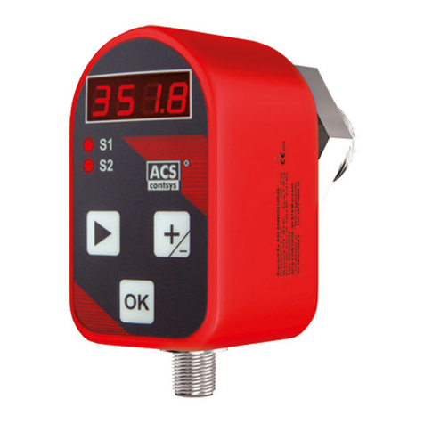
ACS Hydrocont HP4SC User manual

OPERATING MANUAL - BA03.22
Hydrocont HP4SC
Hydrostatic lling level transmitter
with capacitive ceramic measuring membrane

2
www.acs-controlsystem.com
ACS-CONTROL-SYSTEM GmbH | Lauterbachstr. 57 | 84307 Eggenfelden | Germany
YOUR PARTNER FOR MEASUREMENT & AUTOMATION
Index
1 Safety instructions ��������������������������������������������������������������������������������������������������������������������������������������������������3
1.1 Authorized personnel.................................................................................................................................................................... 3
1.2 Terms .............................................................................................................................................................................................. 3
1.3 Appropriate use ............................................................................................................................................................................. 3
1.4 Operational safety......................................................................................................................................................................... 3
2 Product description�������������������������������������������������������������������������������������������������������������������������������������������������4
2.1 Product code.................................................................................................................................................................................. 4
2.2 Function.......................................................................................................................................................................................... 5
2.3 Conguration ................................................................................................................................................................................. 5
2.4 Product label.................................................................................................................................................................................. 5
2.5 Packaging, transport, storage..................................................................................................................................................... 5
3 Installation ����������������������������������������������������������������������������������������������������������������������������������������������������������������6
3.1 Ambient and process conditions ................................................................................................................................................. 6
3.2 Installation place ........................................................................................................................................................................... 6
3.3 Installation notes ........................................................................................................................................................................... 6
3.4 Field enclosure............................................................................................................................................................................... 7
4 Electrical connection����������������������������������������������������������������������������������������������������������������������������������������������� 7
4.1 Electronic output 09-A – 4…20mA, FSK interface ................................................................................................................... 7
4.2 Electronic output 09-V – Interface RS485 Modbus-RTU......................................................................................................... 8
5 Operation ������������������������������������������������������������������������������������������������������������������������������������������������������������������9
5.1 Electronic output 09-A – 4…20mA, FSK interface................................................................................................................... 9
5.2 Electronic output 09-V – Interface RS485 Modbus-RTU......................................................................................................... 9
6 Service ���������������������������������������������������������������������������������������������������������������������������������������������������������������������10
6.1 Maintenance................................................................................................................................................................................. 10
6.2 Dismounting................................................................................................................................................................................. 10
6.3 Troubleshooting / Repair............................................................................................................................................................ 10
6.4 Return........................................................................................................................................................................................... 10
6.5 Disposal ........................................................................................................................................................................................ 10
7 Technical Data ���������������������������������������������������������������������������������������������������������������������������������������������������������11
7.1 Filling level sensor ........................................................................................................................................................................11
7.2 Field enclosure............................................................................................................................................................................. 12
8 Dimensions�������������������������������������������������������������������������������������������������������������������������������������������������������������� 13
8.1 Sensor........................................................................................................................................................................................... 13
8.2 Field enclosure............................................................................................................................................................................. 13
9 Accessories�������������������������������������������������������������������������������������������������������������������������������������������������������������� 14
9.1 Mounting clamp........................................................................................................................................................................... 14
9.2 Mounting screw ........................................................................................................................................................................... 14
9.3 Field enclosure............................................................................................................................................................................. 14
9.4 Installation material .....................................................................................................................................................................15
9.5 Signal processing..........................................................................................................................................................................15

3
info@acs-controlsystem.de | +49 (0) 8721/9668-0
ACS-CONTROL-SYSTEM GmbH | Lauterbachstr. 57 | 84307 Eggenfelden | Germany
1 Safety instructions
1.1 Authorized personnel
Installation, electrical connection, commissioning, operation, dismounting and disposal of the device must be made by a
qualied and authorized expert according to the information’s in the Operating manual and the relevant standards and rules.
This expert must have read and understood the Operating manual and especially the safety notes. During work on and with
the device, the required personal protective equipment must always be worn.
The Operating manual is part of the device and must be kept always accessible nearest its installation location. All statements
within this document correspond to the information available at the time of printing. Subject to change without prior notice.
1.2 Terms
• NOTE: Notes to prevent failures, malfunctions, damage to devices or plants.
• WARNING: Non-observance of the information may result in serious or fatal personal injury.
1.3 Appropriate use
The device is an electronic hydrostatic lling level transmitter for monitoring, control and continuous measurement of lling
levels in liquids.
The operational reliability of the device is ensured only at the intended use. Inappropriate or incorrect use of this product can
give rise to application specic hazards, e.g. vessel overll through incorrect mounting or adjustment. Damage to property
and persons or environmental contamination can result. Also, the characteristics of the instrument can be impaired.
An inappropriately use, disregarding the Operating manual and the technical rules, using under-qualied personnel, making
unauthorized alterations as well as damage of the device releases the manufacturer from liability for any resulting damage.
This renders the manufacturer‘s warranty null and void.
1.4 Operational safety
The device is safely built and tested according to state-of-the-art technology. The instrument must only be operated in a
technically awless and reliable condition. The operator is responsible for the trouble-free operation of the instrument.
The device may only be used within the permitted operation limits. Every use besides these limits as agreed can lead to
serious dangers.
The materials of the device must be checked for compatibility with the respective application requirements before use. An
unsuitable material can lead to damage, abnormal behavior or destruction of the device and to the resulting dangers.
The sensors may not be used as sole device for prevention of dangerous conditions in machines and plants.
For safety and warranty reasons, any invasive work on the device beyond that described in the Operating manual may be
carried out only by personnel authorized by the manufacturer. Arbitrary conversions or modications are explicitly forbidden.
For safety reasons, only the accessory specied by the manufacturer must be used.
The device meets the legal requirements of all relevant EU directives. This is conrmed by attaching the CE mark. The
associated EU-Declaration of Conformity can be ordered or downloaded from the homepage.

4
www.acs-controlsystem.com
ACS-CONTROL-SYSTEM GmbH | Lauterbachstr. 57 | 84307 Eggenfelden | Germany
YOUR PARTNER FOR MEASUREMENT & AUTOMATION
2 Product description
2.1 Product code
Hydrocont HP4 [01][02][03][04][05][06][07][08][09][10][11][12][13][14][15][80][94/95/96/97/98/99]
01 Application type S Standard
02 Sensor / material diaphragm Ccapacitive – front-ush / ceramic Al2O3 96%/99,7%
03 Approval S Standard
04 Process connection 0without
05 Material process seal 1FKM/FPM
05 3 EPDM, FDA listed
06 Material process connection V CrNi-steel
06 D CrNi-steel, duplex, sea water resistant
07 Terminal enclosure 0without
07 1 Field enclosure 3pole, IP65, PS [09-A] +[10-0]
07 2 Field enclosure 6pole, IP65, PS [09-V], [09-A]+[10-1]
08 Measuring range pressure 01 0…100 mbar
08 02 0…200 mbar
08 03 0…400 mbar
08 04 0…600 mbar
08 05 0…1 bar
08 07 0…2 bar
08 08 0…4 bar
08 09 0…6 bar
08 10 0…10 bar
08 12 0…20 bar
08 0A 0…1 mwc
08 0B 0…2 mwc
08 0C 0…4 mwc
08 0M 0…5 mwc
08 0D 0…6 mwc
08 0E 0…10 mwc
08 0F 0…20 mwc
08 0L 0…25 mwc
08 0G 0…40 mwc
08 0J 0…50 mwc
08 0K 0…60 mwc
08 0H 0…100 mwc
09 Electronic – Output ACurrent 4…20mA, FSK, 2-wire, over voltage protection
09 V RS485 Modbus-RTU, 4- wire, over voltage protection
10 Electronic – Function 0without
10 1 Temperature Pt100 class B, 3-wire – IEC 60751 [09-A]
10 3 Temperature ≤ ±0,5K [09-V]
11 Process temperature 0Standard -20°C...+70°C (-4°F… 158°F)
12 Pressure type RGauge pressure
13 Measurement pressure - accuracy 10,2%
13 3 0,1%, linearization protocol
13 6 Xcellence – 0,05% ([08] ≥ 200mbar/2mWS), linearization protocol
14 Electrical connection K Cable, confection stranded wires (length L1 +240mm)
14 H Cable, confection Hydrolog HLF4 (length L1 -360mm)
14 0 Cable, without confection (incl. confection kit)
15 Material extension cable ACable sheath PE
15 B Cable sheath PUR
15 G Cable sheath PUR, increased diffusion-tightness
80 Length L1 -###.### mm (≤ 300.000mm)
94 Additional option -SF LABS-free, silicone-free / paint compatible version
95 Additional option -ML Measurement point designation / TAG – Laser marking
96 Additional option -MZ Material test certicate – EN10204 3.1
97 Additional option -WT Factory certication – drink water suitability
98 Additional option -KF Conguration / Preset
99 Additional option -WK Factory calibration – calibration certicate

5
pi
Io
= 0..1bar
S/N: 482569/2022
HP4SCS01V005A00R1K-10000
= 4..20mA
1 = L+ / Cio
2 = nc
Us
= 9..35VDC
3 = L- / Io
4 = nc
1
2
3
4
1
3
4
5
2
6
Cio
= FSK
84307 Eggenfelden / Germany
www.acs-controlsystem.com
1
32
4
info@acs-controlsystem.de | +49 (0) 8721/9668-0
ACS-CONTROL-SYSTEM GmbH | Lauterbachstr. 57 | 84307 Eggenfelden | Germany
2.2 Function
The device is suitable for applications in virtually all industries for lling and water level measurement, especially for fresh
water, wastewater and salt water. The slim construction design allows the use especially at conned space conditions, e.g. at
bore holes and wells with small diameter.
The high precise, long term stable and robust ceramic measuring cell, the stainless steel enclosure and the thick-walled,
length stable extension cable with highly stressable steel core ensures reliable precise measuring values and allows the
operation also at demanding environmental conditions, e.g. low temperatures, high shock and vibration loads or at
problematic liquids.
The hydrostatic liquid pressure acts directly (dry system) via the process diaphragm to the capacitor at the back side. The
pressure causes there a capacitance change which is converted into a corresponding output signal.
For optional measuring the temperature, an integrated long-term stable platinum temperature sensor is used. The measured
temperature value can be read out at the version 09-V (RS485 Modbus-RTU) by the digital interface or the resistance signal
can be evaluated at the version 09-A (current 4…20mA FSK) in parallel to the pressure conditioned analogue current signal
per 3-wire-technology.
The parameterization and operation can be made by the integrated wired interface.
2.3 Conguration
The device consists on the components:
① Measuring cell ③ Extension cable
② Electronic enclosure ④ Ventilation/pressure compensation
2.4 Product label
The type label contains the most important data for identication and use of the instrument.
① Type code ④ Assignment
② Serial number ⑤ Safety notes
③ Technical data ⑥ Approvals
Illustration exemplary
2.5 Packaging, transport, storage
The device is protected by packaging. It can handle normal loads during transport. Transport must be carried out in due
consideration of the notes on the transport packaging.
Nonobservance of these instructions can cause damage to the device.
The delivery must be checked for completeness and possible transit damage immediately at receipt. Ascertained transit
damage or concealed defects must be appropriately dealt with.
Dispose of the packaging material via specialized recycling companies.
Up to the time of installation, the packages must be left closed and, unless otherwise indicated, must be stored only under
the following conditions:
• Not in the open
• Dry and dust free
• Not exposed to corrosive media
• Protected against solar radiation
• Avoiding mechanical shock and vibration
• Storage and transport temperature -20…+85°C
• Relative humidity 20…85%

6
1
3
2
4
5
6
www.acs-controlsystem.com
ACS-CONTROL-SYSTEM GmbH | Lauterbachstr. 57 | 84307 Eggenfelden | Germany
YOUR PARTNER FOR MEASUREMENT & AUTOMATION
3 Installation
3.1 Ambient and process conditions
The correct function of the device within the specic technical data can only be guaranteed, if the permitted ambient and
process conditions at the installation place (see chapter Technical Data) will not be exceeded. Hence make sure before
mounting that all parts of the instrument exposed to the process (e.g. measuring membrane, process seal, enclosure,
extension cable) are suitable for the existing process conditions (e.g. process pressure, process temperature, chemical
properties of the medium, abrasion, mechanical inuences).
3.2 Installation place
The device should be installed at a point free from ow and turbulence, or a guide tube should be used. The internal
diameter of the guide tube should be at least 1 mm bigger than the outer diameter of the device.
Install device below the lowest measuring point.
Do not mount the device in the ll ow, in the suction area of a pump, in the tank outlet or at a point in the container which
could be affected by pressure pulses from an agitator.
The installation of the device should be made if possible at temperature calmed places. High process temperature steps can
produce short-time higher measuring signal deviations.
At underrun of the dew point, e.g. cold process medium at high environmental temperature, there is the possibility of
condensate formation within the pressure measuring sensor, which can lead to temporary increased measurement deviations
resp. malfunctions. These deviations are fully reversible by drying the condensate.
The cable must end in a dry room or a suitable terminal box.
① Filling level sensor ④ Mounting clamp – see accessories
② Guide pipe ⑤ Mounting screw – see accessories
③ Extension cable (bending radius > 80mm) ⑥ Field enclosure
3.3 Installation notes
Do not remove packaging until just before mounting and check the device for any damage. The transport protection cap,
which is attached at the process connection resp. the diaphragm, must only be removed immediately before the installation.
The transport protection cap must be removed. The diaphragm may not be damaged.
Pollution or damaging of the pressure compensation capillary can lead to faulty measuring results.
If the cable is shortened, the lter at the pressure compensation tube has to be reattached.
WARNING: Install the device only when the system is pressureless. There is a risk of fast escaping media resp. pressure blow.
WARNING: Let the system cool down sufciently before installing the device. There is a risk of dangerous and hot media
escaping.

7
4
20
mA
t
“1” “0” “1”
1200Hz 2200Hz 1200Hz
digital
data signal
analog
current signal
I
I +0,5mA
I -0.5mA
L+
L-
RD
BK
YE/GN
mA
FSK-Interface
240R
USB
Pt100
Pt100
YE
GN
GY
Pt-B2
Pt-B1
Pt-A1
L+
L-
RD
BK
YE/GN
mA
FSK-Interface
240R
USB
info@acs-controlsystem.de | +49 (0) 8721/9668-0
ACS-CONTROL-SYSTEM GmbH | Lauterbachstr. 57 | 84307 Eggenfelden | Germany
4 Electrical connection
WARNING: Install the device only in de-energized state.
NOTE: For start-up deactivate all connected control devices, to avoid unwanted control reactions.
The device must be grounded, preferred by the metallic process connection, alternatively by the cable shield.
The optional eld enclosure can be connected to earth by the connection screw PE/PA at the side of the enclosure.
Install cable separated from power leading cables, if existing connect shield to earth.
Cable: M12 – A-coded, 1-BN = brown / 2-WH = white / 3-BU = blue / 4-BK = black
4.1 Electronic output 09-A – 4…20mA, FSK interface
The digital communication protocol uses Frequency Shift Keying (FSK) technology and is superimposing onto the analogue
sensor signal 4…20mA. This allows a two-way-communication and thus allows the transmission of additional information’s,
that going above the normal process variables, from or to an intelligent eld device.
The communication protocol communicates with 1.200 Bit/s without interrupting the 4…20mA signal an thus allows the host
application (master), to receive two or more digital actualizations per seconds from an intelligent eld device. The digital
signal does not disturb the 4…20mA.
The communication protocol offers two simultaneous communication channels: the analogue 4…20mA signal and a digital
signal. The 4…20mA signal transmits the primary measuring value by the 4…20mA current loop, the fastest and most reliable
industry standard. The digital signal transmits additional information’s from the device like device state, diagnosis date,
additional measuring values or calculated values, etc.
The combination of both principles in one installation allows a cost effective and especially robust comprehensive eld
communication solution, which can be simply uses and congured.
Use a cable 2-core, twisted, shielded.
Observe maximum permitted supply voltage Us at the terminals L+/L-:
• Us = 9…35VDC
Observe maximum permitted load resistor RL of the analogue output:
• RL ≤ (Us - 9V) / 22mA
Option electronic function 10-0
Connection current 4…20mA FSK
Option electronic function 10-0
Connection current 4…20mA FSK / Pt100 – 3-wire
Consider resistor 240Ω within wire +L for connection of the FSK-communication device.
3.4 Field enclosure
For connection of hydrostatic lling level sensors with reference air compensation an air pressure compensation element
is installed at the side of the eld enclosure. This may not be damaged or polluted, otherwise this can lead to wrong
measurements of the lling level sensor and to the resulting dangers.
After installing the device check if all cable glands as well as the enclosure cover are tightly screwed.

8
DR
DR
C / L-
B-
A+
Slave 1 Slave n
RP
650 Ohm
RP
650 Ohm
5 V
RT
120 Ohm
RT
120 Ohm
R
D
Master
L+
L-
RD
BK
A(+)
B(-)
BN
WH
YE/GN
www.acs-controlsystem.com
ACS-CONTROL-SYSTEM GmbH | Lauterbachstr. 57 | 84307 Eggenfelden | Germany
YOUR PARTNER FOR MEASUREMENT & AUTOMATION
4.2 Electronic output 09-V – Interface RS485 Modbus-RTU
The Modbus protocol is a communication protocol, that base on a master/slave architecture.
All devices are connected by two data wires (A+ / B-) and by one COMMON-wire (C/L-).
An original RS485 allows the connection of 32 slaves within one segment. The device has a load of only 1/8 of the standard
load (Rin ≥ 96 kΩ), thus up to 256 of the devices can be theoretically operated within one network segment. However the
number is limited to 247 due to the Modbus address space.
The both termination resistors RT prevent reections on the data wires. The optimum resistor value depends on the wave
impedance of the used cable, but a value of 120 Ohm is a popular choice.
The polarisation network is necessary, to ensure suitable potentials, if none of the devices transmits and thus the wires
A+ and B- are undened (high impedance). The value for RP depends e.g. on bus load or the termination resistors.
Recommended values are between 450 Ohm and 650 Ohm.
The use of a polarisation network is recommended, to ensure a stable network. Usually the polarisation resistors are
implemented within the master device or they are connectible.
Connect the device at bus topology (line). A stub line must be avoided.
Use a cable 4-core acc. to the EIA485 recommendations:
Impedance 135…165Ω @ 3…20Mhz
Cable capacity < 30pF/m
Cable diameter > 0,64mm
Cable cross section 0,34 mm2 / AWG 22
Loop resistance < 110Ω/km
Shielding Braided shield /shield foil
Cable length 38400 Baud ≤ 1200m
Observe maximum permitted supply voltage Us at the terminals L+/L-:
• Us = 6…35VDC

9
info@acs-controlsystem.de | +49 (0) 8721/9668-0
ACS-CONTROL-SYSTEM GmbH | Lauterbachstr. 57 | 84307 Eggenfelden | Germany
5 Operation
The parameterization and operation can be made by the integrated wired interface, dependent on the electronic variant.
Knowledge concerning the communication technology is provided.
5.1 Electronic output 09-A – 4…20mA, FSK interface
Conguration and data transmission can be made per standard FSK interface (e.g. isHRT USB resp. isHRT USBeX) and
operating software (e.g. PACTware). The use of the DTM isHRT CommDTM resp. ICS Generic HART DTM is recommended.
Information’s for installation resp. using the FSK interface resp. the operating software are not content of this manual.
Note: Damping:
• At a set damping 0s…<1s the communication is only active for 20s after power-up the supply voltage. After establishing
the connection it will be stay active. While this, the damping is set to 1s. After 4 minutes of inactivity the connection will
be terminated and the damping is reset to the set value.
• At a set damping of ≥ 1s the establishing of a communication connection is always possible.
Default settings [Adjustment range]:
Default settings Description
Address 0 [0…15]
Damping 1s [0s…60s] Time till a change at the input has been processed
at the output by 100%.
Start value LRV Nominal lower adjust value LRV < URV
= 4mA Span ≥ 25%
End value URV Nominal upper adjust value LRV < URV
= 20mA Span ≥ 25%
5.2 Electronic output 09-V – Interface RS485 Modbus-RTU
Conguration and data transmission can be made per RS485 interface (e.g. Waveshare 15817) and operating software (e.g.
QModMaster). Information’s for installation resp. using the RS485 interface resp. the operating software are not content of
this manual.
Function code Function
03 Read Holding Register
04 Read Input Register
06 Write Single Register
16 Write Multiple Register
Holding Register – Device settings 2 Byte – Uint16 - R/W
Address Description Default Comment
2000 Modbus ID 1Modbus ID / 1 … 247
2001 Baud-Rate 30 = 1200 / 1 = 2400 / 2 = 4800 / 3 = 9600
4 = 19200 / 5 = 38400 / 6 = 57600 / 7 = 115200
2002 Parity 2 0 = None / 1 = Odd / 2 = Even
2003 Number Stopbits 00 = 1 Stop Bit / 1 = 2 Stop Bit
2004 Word Order 00 = ABCD / 1 = CDAB
Input Register – Values 2 Byte – Read only
Address Data Type Description
1000 UInt16 Device Type
1001 UInt32 Serial Number
1003 UInt16 Calibration Date
1004 UInt16 Hardware Version
Input Register – Values 4 Byte – Float – Read only
Address Data Type Description
1010 Upper Range PV = Pressure
1012 Lower Range PV = Pressure
1014 Maximum PV = Pressure
1016 Minimum PV = Pressure
1018 Upper Range SV = Temperature
1020 Lower Range SV = Temperature
1022 Maximum SV = Temperature
1024 Minimum SV = Temperature
Input Register – Values Read only
Address Byte / Type Description Comment

10
www.acs-controlsystem.com
ACS-CONTROL-SYSTEM GmbH | Lauterbachstr. 57 | 84307 Eggenfelden | Germany
YOUR PARTNER FOR MEASUREMENT & AUTOMATION
6 Service
6.1 Maintenance
At appropriate use, the device is free of maintenance.
Solid coatings on the diaphragm can lead to faulty measurement results. In this case the diaphragm must be regularly
cleaned. Don’t use sharp resp. hard tools, pressured air or aggressive chemicals. For dismounting the device see chapter
“Dismounting”.
6.2 Dismounting
Use suitable protective clothing, e.g. goggles, gloves.
WARNING: Dismount the device only when power supply is off.
WARNING: Let the device and the system cool down sufciently fore dismounting it. There is a risk of hot surfaces as well as
dangerous and hot media escaping.
WARNING: Dismount the device only when the system is pressureless. There is a risk of fast escaping media resp. pressure
blow.
After dismounting the diaphragm must be tted with protective caps.
6.3 Troubleshooting / Repair
The operator of the system is responsible for taking suitable measures to rectify faults.
In case of malfunction check:
Component / area Check Rectication
Enclosure Damage Replace device resp. send in for repair
Pressure diaphragm Pollution Clean device resp. send in for repair
Damage Replace device resp. send in for repair
Process seal Damage Replace process seal
Use other seal material if necessary
Compensation capillary Pollution Clean capillary resp. send device in for repair
Supply voltage Operating voltage available Switch-on resp. repair operating voltage
Check terminals resp. repair
Operating voltage too low / too high Adapt operating voltage
Load resistance too high Reduce resistance
Increase operating voltage
Connection cable damaged Send in device for repair
For dismounting the device see chapter “Dismounting”.
If the malfunction cannot be eliminated, please contact the manufacturer.
A repair may only be carried out by the manufacturer.
6.4 Return
Enclose necessary information’s for return:
• An exact description of the application.
• The chemical and physical characteristics of the product.
• A short description of the occurred error.
Before returning the device, the following measures must be performed:
• Adhesive product residues e.g. caustic, toxic, radioactive etc. must be removed.
• A returning must be refrained, if it is not possible by 100% to remove the unhealthily product completely.
• The device must be packed damage-proof.
6.5 Disposal
This instrument is not subject to the WEEE directive and the respective national laws. Hence, pass the instrument directly on
to a specialized recycling company and do not use the municipal collecting points.
1100 2 / UInt16 Status Bit 0: 1 = Invalid Measure Value PV
Bit 1: 1 = Invalid Measure Value SV
1101 2 / UInt16 Unit PV = Pressure
1102 4 / Float Measure Value PV = Pressure
1104 2 / UInt16 Unit SV = Temperature
1105 4 / Float Measure Value SV = Temperature
Holding Register – Values 2 Byte – Uint16 – R/W
Address Description Default Comment
2020 Damping Tau 1000 ms / PV = Pressure
2021 Damping Tau 1000 ms / SV = Temperature

11
info@acs-controlsystem.de | +49 (0) 8721/9668-0
ACS-CONTROL-SYSTEM GmbH | Lauterbachstr. 57 | 84307 Eggenfelden | Germany
7 Technical Data
7.1 Filling level sensor
Input
Reference conditions EN/IEC 60770-1: Characteristic deviation – Limit value adjustment
15..25°C (59°F… 77°F) / 860..1060kPa / 45..75%r.F. / ton240s / 24VDC±0,1V / vertical, sensor downside
Measurand pressure/lling level – pi
Sensor type Capacitive cell
Type code 08-01 08-02 08-03 08-04 08-05 08-07 08-08 08-09
Meas. range PN, gauge – FSI 0..0,1bar 0..0,2bar 0..0,4bar 0..0,6bar 0..1 bar 0..2 bar 0..4 bar 0..6 bar
Under-/Overload -1/5 bar -1/5 bar -1/6 bar -1/10 bar -1/10 bar -1/15 bar -1/25 bar -1/40 bar
Burst pressure 5 bar 5 bar 6 bar 10 bar 10 bar 15 bar 25 bar 40 bar
Type code 08-10 08-12 08-0A 08-0B 08-0C 08-0M 08-0D
Meas. range PN, gauge – FSI 0..10 bar 0…20 bar -0..1mwc 0..2mwc 0..4mwc 0..5mwc 0..6mwc
Under-/Overload -1/40 bar -1/40 bar --1/5 bar -1/5 bar -1/6 bar -1/10 bar -1/10 bar
Burst pressure 40 bar 40 bar -5 bar 5 bar 6 bar 10 bar 10 bar
Type code 08-0E 08-0F 08-0L 08-0G 08-0J 08-0K 08-0H
Meas. range PN, gauge – FSI 0..10mwc 0..20mwc 0..25mwc 0..40mwc 0..50mwc 0..60mwc 0..100wc -
Under-/Overload -1/10 bar -1/15 bar -1/25 bar -1/25 bar -1/40 bar -1/40 bar -1/40 bar -
Burst pressure 10 bar 15 bar 25 bar 25 bar 40 bar 40 bar 40 bar -
Resolution FSI ≥ 16 Bit
Characteristic deviation ≤ ±0,05%FSI / ±0,1%FSI / ±0,2%FSI (Hysteresis/Reproducibility negligible)
Inuence of auxiliary power ≤ ±0,002%FSI/V
Inuence of temperature Tk zero ≤ ±0,015%FSI/K, ≤ ±0,75%FSI
Tk span ≤ ±0,015%FSI/K, ≤ ±0,5%FSI (≥0,4bar/4mwc) / ≤ ±0,8%FSI (<0,4bar/4mwc)
Inuence of mounting position ≤ 0,18mbar (Position vertical, sensor topside)
Long term drift zero value ≤ ±0,05bar/year
Measurand temperature – Ti / 10-1
Sensor type Resistor Pt100 / class B / 3-wire – IEC 60751
Measuring range – FSI -20…+70°C (-4°F… 2158F)
Time behavior t90 ≤ 60s
Characteristic deviation ≤ ±0,3K + 0,005 * [Tp]
Measurand temperature – Ti / 10-3
Sensor type Pt1000 – IEC 60751
Measuring range – FSI -20…+70°C (-4°F… 2158F)
Resolution FSI ≥ 16 Bit
Characteristic deviation ≤ ±0,2K + 0,005 * [Tp]
Long term drift ≤ ±0,1K/year
Output 09-A – Current 4…20mA FSK
Analogue output – Io
Signal range 4…20mA: 3,9…20,5mA / dI ≤ 1µA
Permitted load RL ≤ (Us - 9V) / 20,5mA
Time behavior t90 ≤ 2ms (tddp/dda = 0s) / ton ≤ 0,1s (tddp/dda = 0s)
Inuence of auxiliary power ≤ ±0,5µA/V
Inuence of temperature ≤ ±1µA/K
Interface - Cio
Interface type FSK / 1200 Bit/s
Communication resistor ≥ 240Ω, extern
Output 09-V – RS485 Modbus-RTU
Interface - Cio
Interface type RS485, bidirectional / Modbus-RTU / 9600 Baud (4800…38400 Baud)
Input resistance 112kΩ
Time behavior Signal pressure/lling level: t90 ≤ 2ms (td = 0s) / ton ≤ 0,1s (td = 0s)
Signal temperature: t90 ≤ 60s / ton ≤ 0,1s (td = 0s)
Auxiliary power
Supply voltage Us 09-A: Current 4…20mA FSK: 9…35VDC reverse polarity protected / ≤ 2Vpp / ≤ 20,5mA
Ripple voltage Ur 09-V: RS485 Modbus-RTU: 6…35VDC reverse polarity protected / ≤ 2Vpp / ≤ 10mA (no load)
Input current Is
Process conditions
Process temperature Tp -20…+70°C (-4°F… 2158F)
Pressure cycles ≥ 100 Mio. (1,2xPN)

12
www.acs-controlsystem.com
ACS-CONTROL-SYSTEM GmbH | Lauterbachstr. 57 | 84307 Eggenfelden | Germany
YOUR PARTNER FOR MEASUREMENT & AUTOMATION
Environmental conditions
Ambient temperature Ta -20…+70°C (-4°F… 2158F)
Protection level IP68 [≤100m/≤20bar] (EN/IEC 60529)
Climatic classication 4K4H (EN/IEC 60721-3-4)
Shock classication 50g [11ms] (EN/IEC 60068-2-27)
Vibration classication 20g [10…2000 Hz] (EN/IEC 60068-2-6)
EM compatibility Operation device class B / Industrial range (EN/IEC 61326)
Over voltage protection Integrated overvoltage protection (EN/IEC 61000-4-5)
Insulation voltage ≥ 50VDC / all terminals to PE (≥ 500VDC on request)
Rated leakage current 10kA (8/20µs)
Protection class III
Pollution degree 4
Altitude 5000m above NN
MTTF 463,4 years
Weight 0,3kg + (L1 x 0,068kg/m)
Materials
Process wetted Ceramic Al2O3, 99,7% (Measuring range ≤ 1bar/10mWS) / 96% (Measuring range > 1bar/10mWS)
Steel 1.4404/316L, steel 1.4571/316Ti, FKM/FPM, EPDM, PE, PUR
Extension cable Breaking force steel core > 920N
Bending radius > 80mm
Cross-section strands 0,22mm2
Resistance 90Ohm/km
7.2 Field enclosure
Ambient temperature Ta -20…+40°C (-4°F… 104°F)
Protection level IP66 (EN/IEC 60529)
Weight 0,3kg
Material Enclosure PS/PA/PUR, cable gland PA/NBR, pressure compensation element PBT/PTFE, earthing connection CrNi steel
Cable gland 2x M20, clamping area 6…12mm, wrench size 24mm
Terminals 3x/6x 0,2…4mm2

13
7.4
L1 + 240mm
136
22
7.4
L1
136
22
7.4
L1
136
22
94
121
79
115
70
M20x1,5 M20x1,5
130
5
5
5
5
H 57
10
PE/PA
12
info@acs-controlsystem.de | +49 (0) 8721/9668-0
ACS-CONTROL-SYSTEM GmbH | Lauterbachstr. 57 | 84307 Eggenfelden | Germany
8 Dimensions
8.1 Sensor
Electrical connection 14-K
Confection stranded wires
Electrical connection 14-H
Confection Hydrolog HLF4
Electrical connection 14-0
Without confection
Dimensions in mm
8.2 Field enclosure
Dimensions in mm

14
174
44.5
33.3
15
22
G1"
41.5
18
27
20
G 1,5"
60
40
22
94
121
79
115
70
M20x1,5 M20x1,5
130
5
5
5
5
H 57
10
PE/PA
12
www.acs-controlsystem.com
ACS-CONTROL-SYSTEM GmbH | Lauterbachstr. 57 | 84307 Eggenfelden | Germany
YOUR PARTNER FOR MEASUREMENT & AUTOMATION
9 Accessories
Accessories, optimal matched to the device are directly available from the manufacturer.
9.1 Mounting clamp
Mounting clamp, steel galvanized
Art.-No. 65000399
Mounting clamp, CrNi steel
Art.-No. 65001899
Dimensions in mm
9.2 Mounting screw
VSM-1000
Thread ISO 228-1 – G1“, CrNi steel
Gasket FKM/FPM, IP65/IP67
Art.-No. 611000053
VSM-1500
Thread ISO 228-1 – G1½“, CrNi steel
Gasket FKM/FPM, IP65/IP67
Art.-No. 611000055
Dimensions in mm
9.3 Field enclosure
Field enclosure, PS, IP66, 2x KLE M20x1,5
Terminal 3pole – Option output 09-A
Art.-No. 611000231
Field enclosure, PS, IP66, 2x KLE M20x1,5
Terminal 6pole – Option output 09-V
Art.-No. 611000314
Field enclosure, PS, IP66, 2x KLE M20x1,5
Terminal 6pole – Option 09-A + 10-1
signal converter Pt100 installed (order separately)
Art.-No. 611000493
Dimensions in mm

15
info@acs-controlsystem.de | +49 (0) 8721/9668-0
ACS-CONTROL-SYSTEM GmbH | Lauterbachstr. 57 | 84307 Eggenfelden | Germany
9.4 Installation material
BEFK61: Welding socket G1“IG, CrNi steel, gasket backside FKM/FPM Art.-No. 611000648
BEFK60: Welding socket G1½“IG, CrNi steel, gasket backside FKM/FPM Art.-No. 611000120
RD-20Z15: Reduction G2“AG-G1½“IG, CrNi steel, hexagonal Art.-No. 90980080
RD-20Z10: Reduction G2“AG-G1“IG, CrNi steel, hexagonal Art.-No. 611000147
RD-15Z10: Reduction G1½“AG-G1“IG, CrNi steel, hexagonal Art.-No. 90980085
SPK-TKD74: Service pack for shortening extension cable D7,4mm Art.-No. 611000649
Labeling sign, 65x20x0,5mm, CrNi steel, laser marking by customer specication Art.-No. 611000275
9.5 Signal processing
KTM
Pt100 signal converter, passive
In: Pt100, Out: 4…20mA/0…10V, Option switching output PNP
head transmitter
Art.-No. 171000006
TVA-100-U0
Isolation amplier, active, 20..253Vuc
transmitter supply, In-Out: 0/4…20mA/0…10V adjustable
switch cabinet assembly at standard mounting rail, width 22,5mm
Art.-No. 171000012
TVA-120-U0
Isolation amplier, active, 20..253Vuc
transmitter supply, In-Out: 0/4…20mA/0…10V
switch cabinet assembly at standard mounting rail, width 22,5mm
Art.-No. 171000004
WTAU-100-U0
Pt100 isolation amplier, active, 20..253Vuc
In: Pt100, Out: 0/4…20mA/0…10V adjustable
switch cabinet assembly at standard mounting rail, width 22,5mm
Art.-No. 171000008
WTAU-120-U0
Pt100 isolation amplier, active, 20..253Vuc
In: Pt100, Out: 0/4…20mA/0…10V
switch cabinet assembly at standard mounting rail, width 22,5mm
Art.-No. 171000002
GWA-250-U0
Limit value switch, 20..253Vuc
transmitter supply, In: 0/4…20mA/0…10V, Out: 2x relay
switch cabinet assembly at standard mounting rail, width 22,5mm
Art.-No. 171000015
GWAP-250-U0
Limit value switch, 20..253Vuc
In: Pt100, Out: 2x relay
switch cabinet assembly at standard mounting rail, width 22,5mm
Art.-No. 171000016
DPA
Process indicator/Data logger, TFT display, 18…36Vdc/186…253Vac
In: 0/4…20mA/0..10V, Out: 4…20mA/0…10V/4x relay
Field-/panel- or switch cabinet assembly at standard mounting rail
Art.-No. 161000178
Hydrolog HLF4
Data logger with remote transmission 4G/LTE-2G/GSM, Bluetooth LE
battery operation, In: 0/4…20mA/RS485 Modbus-RTU/Digital-In
tube installation
Art.-No. 121000030
DLF4
Data logger with remote transmission 4G/LTE-2G/GSM, Bluetooth LE
battery operation, In: 0/4…20mA/0..10V/RS485 Modbus-RTU/Digital-In
eld installation
Art.-No. 161000377
isHRT USB Interface converter FSK - USB Art.-No. 611000595
Waveshare 15817 Interface converter RS485 - USB Art.-No. 611000588

YOUR PARTNER FOR MEASUREMENT & AUTOMATION
ACS-CONTROL-SYSTEM GmbH
Lauterbachstr. 57
84307 Eggenfelden - Germany
info@acs-controlsystem.de
www.acs-controlsystem.com
+49 (0) 8721-9668-0
FEEL FREE TO
CONTACT US
Table of contents
Other ACS Transmitter manuals
Popular Transmitter manuals by other brands

Honeywell Home
Honeywell Home 5800MINI Installation & setup guide

Masibus
Masibus TT7S Series manual

MuxLab
MuxLab Stereo Hi-Fi Balun Quick installation guide

Technaxx
Technaxx FMT100 user manual

BNB Solutions
BNB Solutions BAS-1000 User & installation manual

Directed Electronics
Directed Electronics WFM100 owner's guide

Nautel
Nautel NX5 AM Operation & maintenance manual

Vectronic Aerospace
Vectronic Aerospace Globalstar TT5 user manual

Labom
Labom PASCAL CS21 0 Series operating instructions

Zenner
Zenner MinoConnect instruction manual

nedis
nedis 5412810330683 quick start guide

Williams Sound
Williams Sound T1-216 Specification sheet