Acson C Series User manual

CEILING CONCEALED
CHILLED WATER FAN COIL UNIT
(C Series)
INSTALLATION MANUAL
IM-CCCW-1100(6)-ACSON
Part No.: R08019025460F
CVR IM-CCCW-1100(4)AC-EN.indd 1CVR IM-CCCW-1100(4)AC-EN.indd 1 12/3/13 12:20:53 PM12/3/13 12:20:53 PM

CVR IM-CCCW-1100(4)AC-EN.indd 2CVR IM-CCCW-1100(4)AC-EN.indd 2 12/3/13 12:20:55 PM12/3/13 12:20:55 PM

English
1-1
Original Instruction
Dimension
Model ABCDEFGHI JKLMNOPQ
CC10CW 808 774 702 741 267 36 662 662 93 225 115 218 76 411 351 211 211
OUTLINE AND DIMENSIONS
Indoor Unit: Ceiling Concealed Fan Coil Unit C Series
All dimensions are in mm
ML K
G
D
150 31
10
51
10
150
31
E
A
BC
F
131
P
4036 40 20
10
N
O
Q
178
133
39 131 40
10
63
WATER OUTLET
All dimensions are in mm
10
D
H
31
150
51
31 150
10
IJ I
KLM
F
C
B
A
E
P
131
40 40
20
36
10
N
O
63
10
40
131
40
133
178
Q
G
IJ I
H
LEFT PIPING
RIGHT PIPING
WATER INLET
WATER OUTLET
WATER INLET
1 IM-CCCW-1100(4)-EN.indd 11 IM-CCCW-1100(4)-EN.indd 1 12/3/13 12:20:12 PM12/3/13 12:20:12 PM

1-2
Dimension
Model ABCDEFGHI JKLMNOPQR
CC15CW
939 914 842 881 267 36 802 802 93 225 114 222 76 412 351 211 211 185
CC20CW
1108 1075 1002 1041 267 36 962 962 93 225 64 272 76 412 351 211 211 179
CC25CW
1243 1209 1137 1176 267 36 1097 1097 93 225 64 272 76 412 351 211 211 206
All dimensions are in mm
31
10
SEE DETAIL A FOR CC15CW
SEE DETAIL B FOR CC20/25CW
DETAIL B FOR CC20/25CW
DETAIL A FOR CC15CW
IJI
10
RG
MLK
D
H
R
31
51
F
C
B
A
P
40 131 40
10
N
O
4013140
Q
36
10
60
133
179
121
162
61
84
E
61
162
SEE DETAIL A FOR CC15CW
SEE DETAIL B FOR CC20/25CW
DETAIL B FOR CC20/25CW DETAIL A FOR CC15CW
121
179
133
84 60
MLK
D
H
31
51
10
10
31R
G
IJI
Q
13140 40
40
13140 P
N
O10
10
36
E
C
B
A
F
R
LEFT PIPING
RIGHT PIPING
WATER OUTLET
WATER INLET
WATER OUTLET
WATER INLET
WATER OUTLET
WATER INLET
WATER OUTLET
WATER INLET
WATER OUTLET
WATER INLET
WATER OUTLET
WATER INLET
1 IM-CCCW-1100(4)-EN.indd 21 IM-CCCW-1100(4)-EN.indd 2 12/3/13 12:20:13 PM12/3/13 12:20:13 PM

English
1-3
Dimension
Model ABCDEFGHI JKL
CC28CW 987 997 920 959 296 36 824 869 131 339 136 367
CC38CW 1292 1297 1225 1264 316 36 824 1174 119 401 147 394
Dimension
Model MNO PQR S TUV
CC28CW 97 600 521 121 213 410 91 137 87 167
CC38CW 97 638 559 186 233 563 156 148 97 149
16
50
31 (CC28CW)
51 (CC38CW)
15
25 R
H
KLM
G
D
371
40
F
CB
A
E
P
S
15 15
15
N
O25
U
T
V
22
160
Q
IJI
All dimensions are in mm
25
31 (CC28CW)
160
22 V
UTC
O
15
15
S15
P
51 (CC38CW)
ML
E
B
A
F
K
D
G371 40
15
16
50
25
R
H
Q
N
IJI
LEFT PIPING
RIGHT PIPING
WATER OUTLET
WATER INLET
WATER OUTLET
WATER INLET
1 IM-CCCW-1100(4)-EN.indd 31 IM-CCCW-1100(4)-EN.indd 3 12/3/13 12:20:13 PM12/3/13 12:20:13 PM

1-4
Dimension
Model ABCDEFGHI JKL
CC30CW 972 988 917 956 384 36 798 866 143 256 162 206
CC40CW 1088 1105 1033 1072 384 36 798 982 143 256 162 206
CC50CW 1342 1358 1287 1326 384 36 798 1236 143 256 159 209
CC60CW 1542 1558 1487 1526 384 36 798 1436 143 256 159 199
Dimension
Model MNO PQR S TUV
CC30CW 173 541 462 173 307 409 359 159 109 196
CC40CW 173 541 462 173 307 467 359 159 109 196
CC50CW 173 541 462 173 307 594 359 156 106 196
CC60CW 183 541 462 173 307 694 359 154 104 196
Q
15
59 188 60
U
T
N
O
15
40 93 40
P
E
C
BA
F
G
R
40
IJI
HD
25
50
15
MLK
S
I
D
H
25
JI
50
40 S G
KLM
R
F
CB
A
E
P
40 93 40
15
N
O
6018859
Q
V
T
U
15
15
All dimensions are in mm
LEFT PIPING
RIGHT PIPING
WATER OUTLET
WATER INLET
WATER OUTLET
WATER INLET
1 IM-CCCW-1100(4)-EN.indd 41 IM-CCCW-1100(4)-EN.indd 4 12/3/13 12:20:14 PM12/3/13 12:20:14 PM

English
1-5
!WARNING !CAUTION
Installation and maintenance should be performed by
qualified persons who are familiar with local code and
regulation, and experienced with this type of appliance.
All field wiring must be installed in accordance with the
national wiring regulation.
Ensure that the rated voltage of the unit corresponds to
that of the name plate before commencing wiring work
according to the wiring diagram.
The unit must be GROUNDED to prevent possible hazard
due to insulation failure.
All electrical wiring must not touch the water piping or any
moving parts of the fan motors.
Confirm that the unit has been switched OFF before
installing or servicing the unit.
Risk of electric shock, can cause injury or death. Disconnect
all remain electric power supplies before servicing.
DO NOT pull out the power cord when the power is ON.
This may cause serious electrical shocks which may result
in the fire hazards.
Keep the indoor and outdoor units, power cable and
transmission wiring, at least 1m from TVs and radios, to
prevent distorted pictures and static. {Depending on the
type and source of the electrical waves, static may be heard
even when more than 1m away}.
•
•
•
•
•
•
•
•
•
Please take note of the following important points when
installing.
Ensure that the drainage piping is connected properly.
If the drainage piping is not connected properly, it may
cause water leakage which will dampen the furniture.
Ensure that the unit’s panel is closed after service or
installation.
Unsecured panels will cause the unit to operate
noisily.
Sharp edges and coil surfaces are potential locations
which may cause injury hazards. Avoid from being in
contact with these places.
Before turning off the power supply set the remote
controller’s ON/OFF switch to the “OFF” position to
prevent the nuisance tripping of the unit. If this is not done,
the unit’s fans will start turning automatically when power
resumes, posing a hazard to service personnel or the user.
Do not install the units at or near doorway.
Do not install the units at area like hot spring or oil
refinery plant where sulphide gas exists.
Do not operate any heating apparatus too close to the
air conditioner unit or use in room where mineral oil,
oil vapour or oil steam exist, this may cause plastic
part to melt or deform as a result of excessive heat or
chemical reaction.
When the unit is used in kitchen, keep flour away from
going into suction of the unit.
This unit is not suitable for factory used where cutting oil
mist or iron powder exist or voltage fluctuates greatly.
Ensure the color of wires of the outdoor unit and
the terminal markings are same to the indoors
respectively.
IMPORTANT : DO NOT INSTALL OR USE THE AIR
CONDITIONER UNIT IN A LAUNDRY ROOM.
Don’t use joined and twisted wires for incoming power
supply.
The equipment is not intended for use in a potentially
explosive atmosphere.
•
•
•
•
•
•
•
•
•
•
•
•
•
INSTALLATION MANUAL
SAFETY PRECAUTIONS
This manual provides the procedures of installation to ensure a safe and good standard of operation for the air
conditioner unit.
Special adjustment may be necessary to suit local requirement.
Before using your air conditioner, please read this instruction manual carefully and keep it for future reference.
This appliance is intended to be used by expert or trained users in shops, in light industry and on farms, or for
commercial use by lay persons.
This appliance is not intended for use by persons, including children, with reduced physical, sensory or mental
capabilities, or lack of experience and knowledge, unless they have been given supervision or instruction concerning
use of the appliance by a person responsible for their safety.
Children should be supervised to ensure that they do not play with the appliance.
NOTICE
Disposal requirement
Your air conditioning product is marked with this symbol. This means that electrical and electronic products shall not
be mixed with unsorted household waste.
Do not try to dismantle the system yourself: the dismantling of the air conditioning system, treatment of the refrigerant,
of oil and of other parts must be done by a qualified installer in accordance with relevant local and national legislation.
Air conditioners must be treated at a specialized treatment facility for re-use, recycling and recovery. By ensuring this
product is disposed of correctly, you will help to prevent potential negative consequences for the environment and human
health. Please contact the installer or local authority for more information.
Batteries must be removed from the remote controller and disposed of separately in accordance with relevant local and
national legislation.
1 IM-CCCW-1100(4)-EN.indd 51 IM-CCCW-1100(4)-EN.indd 5 12/3/13 12:20:14 PM12/3/13 12:20:14 PM

1-6
CORK TAPE FULLY INSULATED
INSULATION THROUGH OUT CHILLED WATER PIPING
The indoor unit must be installed such that there is no short
circuit of the cool discharge. Respect the installation clearance.
Do not put the indoor unit where there is direct sunlight on unit.
The location is suitable for piping and drainage and it must have
a large distance between a door and unit.
Ceiling Concealed Mounting
Use the hanger supplied with the unit.
Make sure that the ceiling is sufficiently strong to withstand
the weight.
•
•
Center distance of axle (see drawing below)
Provide clearance for servicing ease and optimal air flow as
shown in the diagram.
INSTALLATION DIAGRAM
INSTALLATION OF THE INDOOR UNIT
!CAUTION
Do not install the unit at altitude over 2000m for both indoor and outdoor.
A
L
300mm* or more
300mm
or more
10mm
* Can be smaller than 300mm if ceiling is removable.
Floor
2300mm or more
Ceiling
CC CC10CW CC15CW CC20CW CC25CW CC28CW
A (mm) 741 881 1041 1176 959
L (mm) 225 225 225 225 339
CC CC30CW CC38CW CC40CW CC50CW CC60CW
A (mm) 956 1264 1076 1326 1526
L (mm) 266 401 266 266 266
Insulation material
(field supply)
Aluminium tape
(field supply)
Aluminium tape
(field supply)
Air outlet side
Air inlet side
See
Detail A
Field supply
Washer for hanger bracket
(attached)
Tighten
Detail A
1 IM-CCCW-1100(4)-EN.indd 61 IM-CCCW-1100(4)-EN.indd 6 12/3/13 12:20:14 PM12/3/13 12:20:14 PM

English
1-7
Ceiling Concealed Drain Piping Work
Unit : mm
The drain pipe must be installed as shown in the diagram (see diagram above) to avoid damage caused by leaks and
condensation.
For the best result, keep the piping as short as possible. Slant the piping at an angle to improve the flow.
Ensure the drain pipe is securely insulated.
It is necessary to provide a drain trap in the drain outlet to relieve pressure that exists within the unit compared to the outside
atmospheric pressure when the unit is operating. The drain trap is to avoid possibility of splashes or an odor.
Keep pipes as straight as possible for easy cleaning and to prevent the accumulation of dirt and debris.
Conduct a water drainage test after the installation is completed. Make sure that the drainage flow is smooth.
In humid environments, use an extra drain pan to cover the entire area of the indoor unit.
•
•
•
•
•
•
•
Do not leave in water
Bottom of
the unit
or more or more
Drain
trap
S
l
a
n
t
Insulate securely
10mm (0.39")
The indoor unit is equipped with water outlet and inlet connection. There is an air-vent that is fitted along with the connection
for air purging.
3 way valve is required for cycling off or bypass the chilled water.
Black steel pipe, closed cell polyurethane pipe and copper tube are recommended in the field installation. All types of
piping and connection must be insulated with closed cell polyurethane to avoid condensation.
Do not use contaminated or damaged pipe and fitting for installation.
Some main fitting components are needed in the system to enhance the capacity and ease of service, such as gate valve,
balancing valve, 2 way or 3 way valve, filter, strainer and etc.
•
•
•
•
•
Chiller
Gate Valve
Gate Valve
FCU
Three Way Valve Gate Valve
Gate Valve
FCU
Two Way Valve
Good Controlling Bad Controlling
Gate Valve
Gate Valve
FCU
Worst Controlling
WATER PIPING CONNECTION
100 100
1 IM-CCCW-1100(4)-EN.indd 71 IM-CCCW-1100(4)-EN.indd 7 12/3/13 12:20:15 PM12/3/13 12:20:15 PM

1-8
Wire connection to the controller board is as show in the wiring diagram on the respective terminal box.
The standard controller board comes with a VALVE jumper and a HEAT jumper. The system must be configurated as the
jumper selection listed below:
HEAT Jumper VALVE Jumper
Cooling Mode & Valve Application x P
Cooling Mode & Valveless Application x x
Heatpump Mode & Valve Application PP
Heatpump Mode & Valveless Application Px
Example: If the unit is running “Heatpump Mode & Valveless Application”, remain the HEAT jumper while remove the
VALVE jumper.
CC10CW / 15CW / 20CW / 25CW (without controller)
FCU 1 FCU 2 FCU 3
FSC
X2
X1
Chiller
FL FM FH L N
!There must be an all pole
disconnection in the supply
mains with a contact separation
of at least 3mm.
All power line must be from
the same phase.
ELECTRICAL WIRING CONNECTION
TH
220-240V/1ø/50Hz or
208-230V/1ø/60Hz
TH
X3 220-240V/1ø/50Hz or
208-230V/1ø/60Hz
220-240V/1ø/50Hz or
208-230V/1ø/60Hz
TH
FSC FSC
FL FM FH L N FL FM FH L N
L
N
L
N
L
N
FL Fan Low
FM Fan Medium
FH Fan High
L Live
N Neutral
FSC Fan Speed Controller
X1, X2, X3 Relay (220 ~240V, 10A)
TH Thermostat
FCU 1 FCU 2 FCU 3
FSC
X2
X1
Chiller
SH H M L N
TH
220-240V/1ø/50Hz or
208-230V/1ø/60Hz
TH
X3 220-240V/1ø/50Hz or
208-230V/1ø/60Hz
220-240V/1ø/50Hz or
208-230V/1ø/60Hz
TH
FSC FSC
SH H M L N SH H M L N
L
N
L
N
L
N
SH Fan Super High
H Fan High
M Fan Medium
L Fan Low
N Neutral
FSC Fan Speed Controller
X1, X2, X3 Relay (220 ~240V, 10A)
TH Thermostat
CC28CW / 30CW / 38CW / 40CW / 50CW / 60CW (without controller)
!There must be an all pole
disconnection in the supply
mains with a contact separation
of at least 3mm.
All power line must be from
the same phase.
1 IM-CCCW-1100(4)-EN.indd 81 IM-CCCW-1100(4)-EN.indd 8 12/3/13 12:20:15 PM12/3/13 12:20:15 PM

English
1-9
IMPORTANT: * These values are for information only. They should be checked and selected to comply with local and/or
national codes and/or national codes and regulations. They are also subject to the type of installation and
size of conductors.
** The appropriate voltage range should be checked with label data on the unit.
Amain switch or other means for disconnection, having a contact separation in all poles, must be incorporated
in the fixed wiring in accordance with the relevant local and national legislation.
CC10CW / 15CW / 20CW / 25CW / 28CW / 30CW / 38CW / 40CW / 50CW / 60CW (with controller)
X1
3WV
Chiller
VALV E
LN
220-240V/1ø/50Hz or
208-230V/1ø/60Hz
L
N
X2
3WV
VALV E
LN
220-240V/1ø/50Hz or
208-230V/1ø/60Hz
L
N
X3
3WV
VALV E
LN
220-240V/1ø/50Hz or
208-230V/1ø/60Hz
L
N
3WV
3 way valve
Field supply
X1, X2, X3, Relay (220-240V, 10A)
FCU 1 FCU 2 FCU 3
Note:
This is a proposed wiring connection. It may change subject to the chiller unit and must comply with the local and national
code and regulations.
Model Indoor CC10CW CC15CW CC20CW CC25CW CC28CW
Voltage Range** Indoor 220V-240V/1Ph/50Hz + !or 208V-230V/1Ph/60Hz + !
Power Supply Cable Size* mm2
Number of Conductors 1.5
31.5
31.5
31.5
31.5
3
Recommended Time Delay Fuse* A 12446
Model Indoor CC30CW CC38CW CC40CW CC50CW CC60CW
Voltage Range** Indoor 220V-240V/1Ph/50Hz + !or 208V-230V/1Ph/60Hz + !
Power Supply Cable Size* mm2
Number of Conductors 1.5
31.5
31.5
31.5
31.5
3
Recommended Time Delay Fuse* A 8 10101012
!There must be an all pole
disconnection in the supply
mains with a contact separation
of at least 3mm.
All power line must be from
the same phase.
1 IM-CCCW-1100(4)-EN.indd 91 IM-CCCW-1100(4)-EN.indd 9 12/3/13 12:20:15 PM12/3/13 12:20:15 PM

1-10
Attach insulation sleeve
Round crimp-style terminal Electric wire
Connect wires of the
same gauge to both side.
Do not connect wires of the
same gauge to one side.
Do not connect wires
of different gauges.
Use the correct screwdriver for terminal screws tightening. Unsuitable screwdrivers can damage the screw head.
Over tightening can damage the terminal screw.
Do not connect wire of different gauge to same terminal.
Keep wiring in an orderly manner. Prevent the wiring from obstructing other parts and the terminal box cover.
•
•
•
•
All wires must be firmly connected.
Make sure all the wire do not touch the refrigerant pipings, compressor or any moving parts.
The connecting wire between the indoor unit and the outdoor unit must be clamped by using provided cord anchorage.
The power supply cord must be equivalent to H07RN-F which is the minimum requirement.
Make sure no external pressure is applied to the terminal connectors and wires.
Make sure all the covers are properly fixed to avoid any gap.
Use round crimp-style terminal for connecting wires to the power supply terminal block. Connect the wires by matching
to the indication on terminal block. (Refer to the wiring diagram attached on the unit).
•
•
•
•
•
•
•
1 IM-CCCW-1100(4)-EN.indd 101 IM-CCCW-1100(4)-EN.indd 10 12/3/13 12:20:15 PM12/3/13 12:20:15 PM

English
1-11
OVERALL CHECKING
Ensure the following, in particular:-
The unit is mounted solidly and rigid in position.
Piping and connections are leak proof after charging.
Proper wiring has been done.
Drainage check:- Pour some water into left side of drain pan (drainage are in right side of unit).
Note:
The installation guide above covers only the fan coil unit. For installation guide of outdoor (chiller mini etc) please refer
to the installation guide for such unit.
The installation of fan coil unit may vary according to the type of outdoor unit.
Installation must be done by qualified personnel who are familiar with this type of product.
1.
2.
3.
•
•
•
INDICATOR LIGHTS
Error Description Cool LED Error Indication
Room Sensor error 1 blinks E1
Pipe Water Sensor error 2 blinks E2
Water Pump error 3 blinks E6
Pipe Water Temperature fault 5 blinks E5
Operating Limits:
Thermal carrier : Water
Water temperature : 4°C ~ 10°C (Cooling), 35°C ~ 50°C (Heating),
Maximum water pressure : 16 bar
Air temperature : (as below)
Cooling Mode Heating Mode
Ts: Dry bulb temperature. Th: Wet bulb temperature.
OPERATING RANGE
Temperature Ts °C/°F Th °C/°F
Minimum indoor
temperature 19.0 / 66.2 14.0 / 57.2
Maximum indoor
temperature 32.0 / 89.6 23.0 / 73.4
Temperature Ts °C/°F Th °C/°F
Minimum indoor
temperature 15.0 / 59.0 -
Maximum indoor
temperature 27.0 / 80.6 -
1 IM-CCCW-1100(4)-EN.indd 111 IM-CCCW-1100(4)-EN.indd 11 12/3/13 12:20:16 PM12/3/13 12:20:16 PM

1-12
For any enquiries on spare part please contact your authorized dealer. When any malfunction of the air
conditioner unit is noted, immediately switch off the power supply to the unit. Check the following fault
conditions and causes for some simple troubleshooting tips.
If the fault persists, please call your local dealer / serviceman.
TROUBLESHOOTING
Fault Causes / Action
The air conditioner unit does not operate.1. Power failure, or the fuse need to be replaced.
The power plug is disconnected.
It is possible that your delay timer has been set
incorrectly.
–
–
–
The air flow is too low.2. The air filter is dirty.
The air suction and discharge are clogged.
The regulated temperature is not high enough.
(applicable for auto fan mode only)
–
–
–
Discharge air flow has bad odor.3. Odors may be caused by cigarettes, smoke particles,
perfume etc. which might have adhered onto the coil.
–
Condensation on the front air grille of the indoor unit.4. This is caused by air humidity after an extended long
period of operation.
The set temperature is too low, increase the
temperature setting and operate the unit at high fan
speed.
–
–
Water flowing out from the air conditioner unit.5. Switch off unit and call local dealer / serviceman.–
SERVICE AND MAINTENANCE
!CAUTION
Avoid direct contact of any coil treatment cleaners on plastic part. This may cause plastic part to deform as a result of
chemical reaction.
Service Parts Maintenance Procedures Period
Indoor Air Filter Remove any dust adhered on the filter by using a vacuum cleaner or
wash in lukewarm water (below 40°C) with neutral cleaning detergent.
Rinse the filter well and dry before placing it back onto the unit.
Do not use gasoline, volatile substances or chemical to clean the filter.
1.
2.
3.
At least once every
2 weeks.
More frequently if
necessary.
Indoor Unit Clean any dirt or dust on the grille or panel by wiping it off with soft
cloth soaked in lukewarm water (below 40°C) with neutral detergent
solution.
Do not use gasoline, volatile substances or chemicals to clean the indoor
unit.
1.
2.
At least once every
2 weeks.
More frequently if
necessary.
Indoor Fan Check for any abnormal noise.1. When necessary
1 IM-CCCW-1100(4)-EN.indd 121 IM-CCCW-1100(4)-EN.indd 12 12/3/13 12:20:16 PM12/3/13 12:20:16 PM

Français
2-1
CONTOUR ET DIMENSIONS
Unité Intérieure : Ventilo-convecteur de série C dissimulé dans le plafond
Traduction des instructions d’origine
Dimension
Modèle ABCDEFGHI JKLMNOPQ
CC10CW 808 774 702 741 267 36 662 662 93 225 115 218 76 411 351 211 211
ML K
G
D
150 31
10
51
10
150
31
E
A
B
C
F
131
P
4036 40 20
10
N
O
Q
178
133
39 131 40
10
63
Toutes les dimensions sont données en mm
10
D
H
31
150
51
31 150
10
IJ I
KLM
F
C
B
A
E
P
131
40 40
20
36
10
N
O
63
10
40
131
40
133
178
Q
G
IJ I
H
Toutes les dimensions sont données en mm
TUYAUTERIE GAUCHE
TUYAUTERIE DROITE
SORTIE D’EAU
ENTRÉE D’EAU
SORTIE D’EAU
ENTRÉE D’EAU
2 IM-CCCW-1100(4)-FR.indd 12 IM-CCCW-1100(4)-FR.indd 1 12/3/13 12:19:11 PM12/3/13 12:19:11 PM

2-2
Dimension
Modèle ABCDEFGHI JKLMNOPQR
CC15CW
939 914 842 881 267 36 802 802 93 225 114 222 76 412 351 211 211 185
CC20CW
1108 1075 1002 1041 267 36 962 962 93 225 64 272 76 412 351 211 211 179
CC25CW
1243 1209 1137 1176 267 36 1097 1097 93 225 64 272 76 412 351 211 211 206
61
162
VOIR DÉTAIL A POUR CC15CW
VOIR DÉTAIL B POUR 20/25CW
DÉTAIL B POUR CC20/25CW DÉTAIL A POUR CC15CW
121
179
133
84 60
MLK
D
H
R
31
51
10
10
31
R
G
IJI
Q
13140 40
40
13140 P
N
O10
10
36
E
C
B
A
F
31
10
VOIR DÉTAIL A POUR CC15CW
VOIR DÉTAIL B POUR 20/25CW
DÉTAIL B POUR CC20/25CW
DÉTAIL A POUR CC15CW
IJI
10
RG
MLK
D
H
R
31
51
F
C
B
A
P
40 131 40
10
N
O
4013140
Q
36
10
60
133
179
121
162
61
84
TUYAUTERIE GAUCHE
TUYAUTERIE DROITE
E
Toutes les dimensions sont données en mm
SORTIE D’EAU
ENTRÉE D’EAU
SORTIE D’EAU
ENTRÉE D’EAU
SORTIE D’EAU
ENTRÉE D’EAU
SORTIE D’EAU
ENTRÉE D’EAU
ENTRÉE D’EAU
SORTIE D’EAU
SORTIE D’EAU
ENTRÉE D’EAU
2 IM-CCCW-1100(4)-FR.indd 22 IM-CCCW-1100(4)-FR.indd 2 12/3/13 12:19:11 PM12/3/13 12:19:11 PM

Français
2-3
25
31 (CC28CW)
160
22
V
U
TC
O
15
15
S15
P
51 (CC38CW)
ML
E
B
A
F
K
D
G371 40
15
16
50
25
R
H
Q
N
IJI
Dimension
Modèle ABCDEFGHI JKL
CC28CW 987 997 920 959 296 36 824 869 131 339 136 367
CC38CW 1292 1297 1225 1264 316 36 824 1174 119 401 147 394
Dimension
Modèle MNO PQR S T UV
CC28CW 97 600 521 121 213 410 91 137 87 167
CC38CW 97 638 559 186 233 563 156 148 97 149
16
50
31 (CC28CW)
51 (CC38CW)
15
25 R
H
KLM
G
D
371
40
F
CB
A
E
P
S
15 15
15
N
O25
U
T
V
22
160
Q
I
JI
TUYAUTERIE GAUCHE Toutes les dimensions sont données en mm
Toutes les dimensions sont données en mm
TUYAUTERIE DROITE
SORTIE D’EAUENTRÉE D’EAU
2 IM-CCCW-1100(4)-FR.indd 32 IM-CCCW-1100(4)-FR.indd 3 12/3/13 12:19:12 PM12/3/13 12:19:12 PM

2-4
Dimension
Modèle ABCDEFGHI JKL
CC30CW 972 988 917 956 384 36 798 866 143 256 162 206
CC40CW 1088 1105 1033 1072 384 36 798 982 143 256 162 206
CC50CW 1342 1358 1287 1326 384 36 798 1236 143 256 159 209
CC60CW 1542 1558 1487 1526 384 36 798 1436 143 256 159 199
Dimension
Modèle MNO PQR S T UV
CC30CW 173 541 462 173 307 409 359 159 109 196
CC40CW 173 541 462 173 307 467 359 159 109 196
CC50CW 173 541 462 173 307 594 359 156 106 196
CC60CW 183 541 462 173 307 694 359 154 104 196
Q
15
59 188 60
U
T
N
O
15
40 93 40
P
E
C
BA
F
G
R
40
IJI
HD
25
50
15
MLK
S
I
D
H
25
JI
50
40 S G
KLM
R
F
CB
A
E
P
40 93 40
15
N
O
6018859
Q
V
T
U
15
15
Toutes les dimensions sont données en mm
TUYAUTERIE GAUCHE
TUYAUTERIE DROITE Toutes les dimensions sont données en mm
SORTIE D’EAU
ENTRÉE D’EAU
SORTIE D’EAU
ENTRÉE D’EAU
2 IM-CCCW-1100(4)-FR.indd 42 IM-CCCW-1100(4)-FR.indd 4 12/3/13 12:19:12 PM12/3/13 12:19:12 PM

Français
2-5
PRÉCAUTIONS DE SÉCURITÉ
!ATTENTION !AVERTISSEMENT
L’installation et la maintenance doivent être exécutées par
une personne qualifiée qui est familiarisée avec les lois et
réglementations en vigueur, et aussi expérimentée dans ce
type d’équipements.
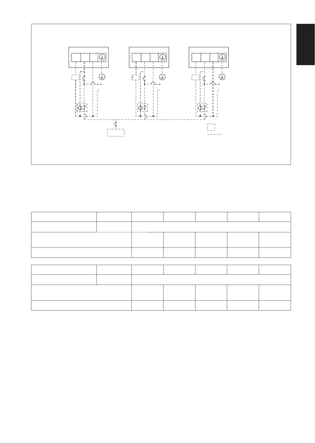
Tous les câblages doivent répondre aux réglementations
électriques nationales.
Avant de commencer le raccordement suivant le schéma
électrique, s’assurer que la tension nominale de l’appareil
corresponde bien à celle indiquée sur la plaque signalétique.
L’unité doit être raccordée à la TERRE pour prévenir tous les
risques possibles dûes à un défaut d’isolation.
Aucun câble électrique ne doit toucher la tuyauterie d’eau ou
des pièces mobiles des moteurs des ventilateurs.
Avant l’installation ou l’entretien du climatiseur, s’assurer que
l’appareil est éteint (OFF).
Risque de décharge électrique pouvant entraîner des blessures,
voire la mort. Débrancher toutes les alimentations électriques
restantes avant l’entretien.
NE PAS retirer le câble d’alimentation électrique de la prise
quand l’appareil est sous branché. Il peut en résulter des
décharges électriques importantes susceptibles de provoquer
un incendie.
Les unités intérieures et extérieures, le cordon d’alimentation
et le câblage de transmission doivent rester à une distance
d’au moins 1m des téléviseurs et des radios, ce afin d’éviter
les images déformées et les parasites. {En fonction du type et
de la source des ondes électriques, des parasites peuvent être
entendus même avec une distance supérieure à 1m}.
•
•
•
•
•
•
•
•
•
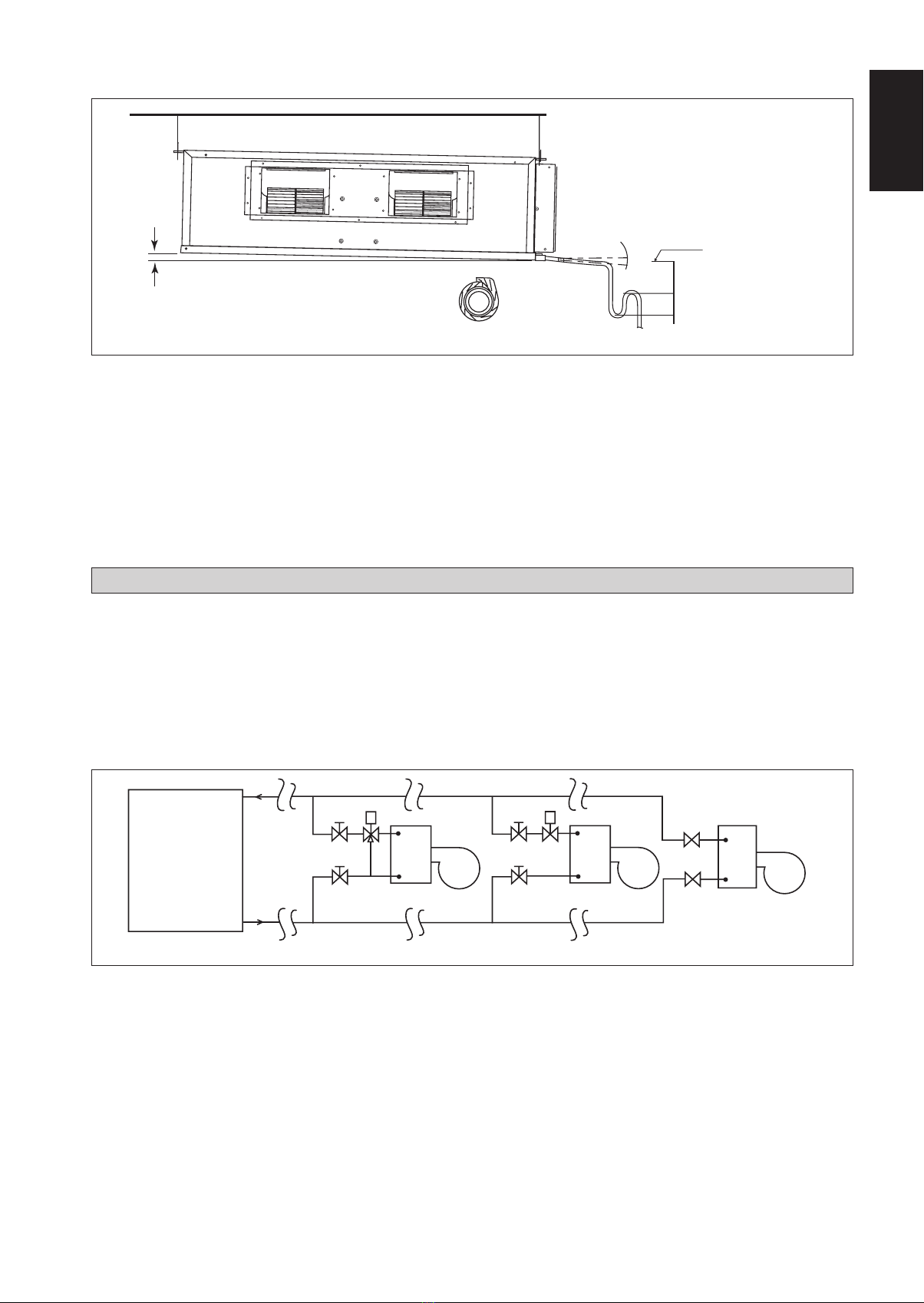
Vérifier les points suivants au cours de l’installation.
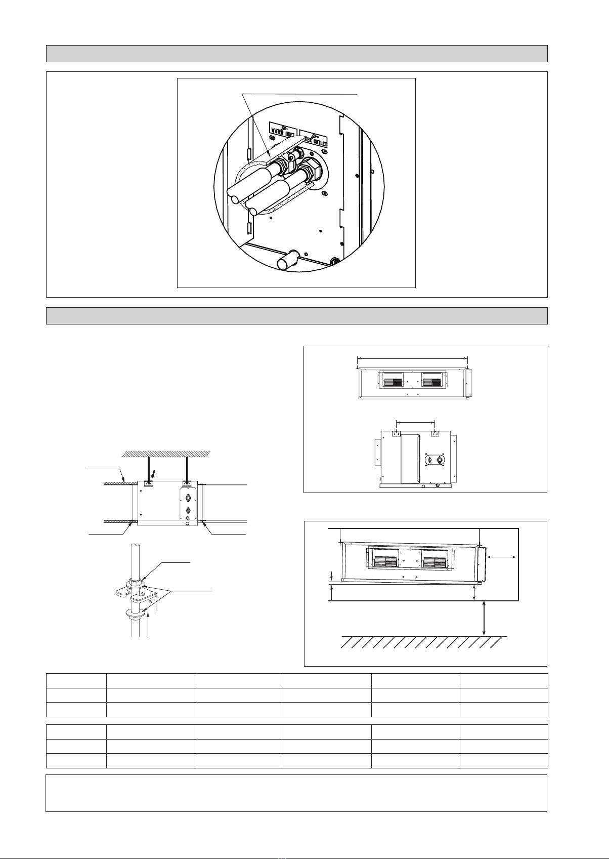
S’assurerque le tuyau d’évacuation du condensat est correctement
branché.
Si le tuyau d’évacuation n’est pas correctement branché, les
éventuelles fuites d’eau risquent de mouiller le mobilier.
S’assurer que le panneau supérieur de l’appareil est remis en
place après l’installation ou l’entretien.
Avec un panneau mal fixé l’appareil va fonctionner
bruyamment.
Les bords coupants et les surfaces du refroidisseur tuulaire
présentent un risque de blessure. Mieux vaut éviter le contact
avec ces endroits.
Avant de couper l’alimentation électrique, veiller à ce que
l’interrupteur ON/OFFde la télécommande soit en position « OFF
» afin d’éviter une mise en marche intempestive de l’appareil. Si
l’interrupteur de la télécommande n’est pas en position « OFF », les
ventilateurs de l’appareil se mettront en marche dès que l’alimentation
électrique est rétablie. Il peut en résulter un danger pour le personnel
d’entretien ou l’utilisateur.
Ne pas installer les appareils à proximité ou près d’un passage
de porte.
Ne pas installer les unités à des endroits comme une source
d’eau chaude ou une raffinerie de pétrole où des gaz sulfureux
existent.
Ne pas utiliser un appareil de chauffage trop près d’une unité de
climatisation ou l’utiliser dans une pièce où, de l’huile minérale
ou de la vapeur d’huile existent, cela peut faire fondre ou se
déformer les pièces en plastique en raison de la chaleur excessive
ou de réaction chimique.
Lorsque l’appareil est utilisé dans la cuisine, le garder loin de la
farine qui peut aller dans d’aspiration de l’appareil.
Cet appareil n’est pas approprié pour une utilisation en usine
lorsqu’un brouillard d’huile de coupe ou de la poudre de fer existe
ou bien quand la tension fluctue grandement.
S’assurer que la couleur des câbles de l’unité extérieure et
les marquages de bornes sont identiques à ceux de l’unité
intérieure.
IMPORTANT: NE PAS INSTALLER OU UTILISER LE
CLIMATISEUR DANS UNE BUANDERIE.
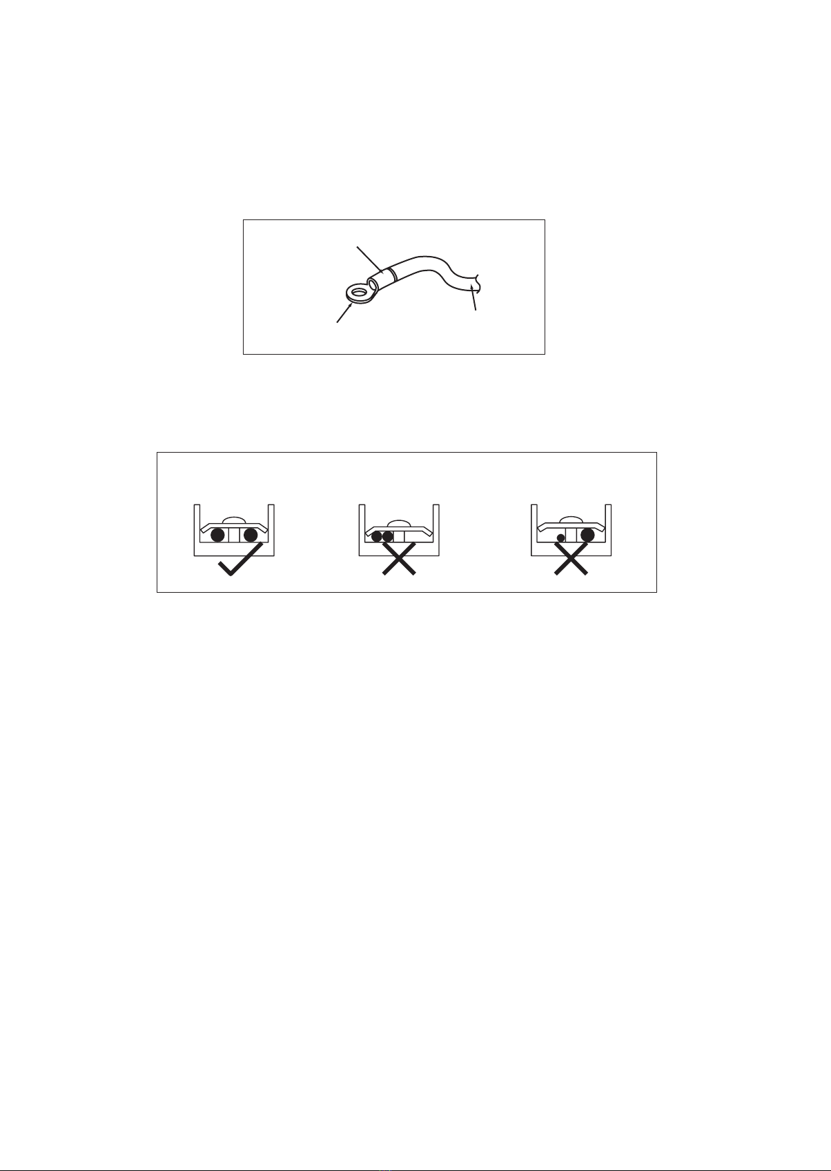
N’utilisez pas de câbles joints et torsadés pour l’alimentation
électrique entrante.
Lʼéquipement nʼest pas conçu pour une utilisation dans une
atmosphère potentiellement explosive.
•
•
•
•
•
•
•
•
•
•
•
•
•
MANUEL D’INSTALLATION
Ce manuel fournit les procédures d’installation pour assurer le bon fonctionnement et la sécurité de cet appareil.
Des ajustements peuvent être nécéssaires pour suivre les réglementations locales.
Avant d’installer et de faire fonctionner le climatiseur, lisez attentivement ce manuel et conservez le.
Cet appareil est destiné à être utilisé par des utilisateurs experts ou formés dans les magasins, dans l’industrie légère ou dans les fermes,
oupour un usage commercial par des personnes non spécialisées.
Cet appareil n’est pas destiné à être utilisé par des personnes, y compris les enfants, souffrant de capacités physiques, sensorielles ou
mentales réduites, ou accusant un manque d’expérience et de connaissances, sauf si elles sont supervisées ou ont reçu des instructions
concernant l’emploi de cet appareil d’une personne responsable de leur sécurité.
Les enfants doivent être supervisés pour s’assurer qu’ils ne jouent pas avec l’appareil.
AVIS
Instructions d’élimination
Cet appareil de conditionnement d’air porte le symbole ci-joint. Ce symbole signifie que les appareils électriques et électroniques doivent être éliminés
séparément des ordures ménagères non triées.
N’essayez pas de démonter vous-même l’appareil : le démontage de l’appareil de conditionnement d’air ainsi que le traitement du réfrigérant, de l’huile
et d’autres composants doivent être effectués par un installateur qualifié, en accord avec les réglementations locales et nationales en vigueur.
Les appareils de conditionnement d’air doivent être traités dans des installations spécialisées de dépannage, réutilisation ou recyclage. En vous assurant
que cet appareil est éliminé correctement, vous contribuez à éviter les conséquences potentiellement néfastes sur l’environnement et la santé. Veuillez
contacter votre installateur ou les autorités locales pour plus d’information.
Les piles de la télécommande doivent être enlevées et éliminées séparément, conformément aux réglementations locales et nationales en vigueur.
2 IM-CCCW-1100(4)-FR.indd 52 IM-CCCW-1100(4)-FR.indd 5 12/3/13 12:19:12 PM12/3/13 12:19:12 PM

2-6
Matériau isolant
(alimentation du site)
Bande aluminium
(alimentation du site)
Bande aluminium
(alimentation du site)
Sortie d’air
Entrée d’air
Consulter
le dessin
détaillé A
Alimentation du site
Rondelle pour le support de crochet
(joint)
Serrer
Dessin détaillé A
L’unité intérieure doit être installée de façon à ce qu’il n’y ait
aucun court circuit de l’air d’évacuation froid. Respectez les
dégagements minimums. Ne pas installer l’unité intérieure dans
un emplacement où elle peut être exposée à la lumière directe du
soleil. L’emplacement doit convenir aux tuyauteries et vidange et il
faut prévoir une assez grande distance entre une porte et l’unité.
Montage dissimulé dans le plafond
Utilisez le crochet fourni avec l’unité.
Veillez à ce que le plafond soit suffisamment résistant pour
soutenir le poids.
•
•
Distance centrale de l’axe (consulter le schéma ci-dessous)
Laisser un espace libre pour faciliter la maintenance et obtenir
un flux d’air optimal, comme indiqué sur le schéma.
DIAGRAMME D’INSTALLATION
!AVERTISSEMENT
N’installez pas l’unité, intérieure comme extérieure, à une altitude supérieure à 2000m.
300mm* ou plus
300mm
ou plus
10mm
* Peut être inférieur à 300mm si le plafond est amovible.
Sol
2300mm ou plus
Plafond
A
L
CC CC10CW CC15CW CC20CW CC25CW CC28CW
A (mm) 741 881 1041 1176 959
L (mm) 225 225 225 225 339
CC CC30CW CC38CW CC40CW CC50CW CC60CW
A (mm) 956 1264 1076 1326 1526
L (mm) 266 401 266 266 266
BANDE DE LIÈGE TOTALEMENT ISOLÉE
ISOLATION DES TUYAUTERIES D’EAU GLACÉE
INSTALLATION DE L’UNITÉ INTÉRIEURE
2 IM-CCCW-1100(4)-FR.indd 62 IM-CCCW-1100(4)-FR.indd 6 12/3/13 12:19:13 PM12/3/13 12:19:13 PM
This manual suits for next models
10
Table of contents
Languages:
Other Acson Air Conditioner manuals

Acson
Acson M-CCC-0501-ACSON User manual

Acson
Acson AWM09J User manual

Acson
Acson IM-CCC-0501-ACSON User manual

Acson
Acson awm07f User manual

Acson
Acson E series User manual

Acson
Acson A4LC 10 B User manual

Acson
Acson ACM 28 ER User manual

Acson
Acson AWM 07G User manual

Acson
Acson A5CK20A User manual

Acson
Acson 5CEY15E User manual

Acson
Acson AWM 25GR User manual

Acson
Acson ACM15E User manual

Acson
Acson AWM 301 User manual

Acson
Acson IM-MSDT-0501-ACSON User manual

Acson
Acson 5CEE Series User manual

Acson
Acson ART 55 A User manual

Acson
Acson 5CCY10C/CR User manual

Acson
Acson IM-VCUA-0304-ACSON User manual

Acson
Acson ACC 10C User manual

Acson
Acson WM07G User manual