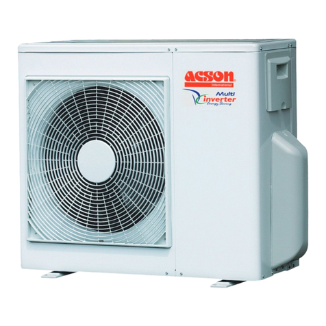
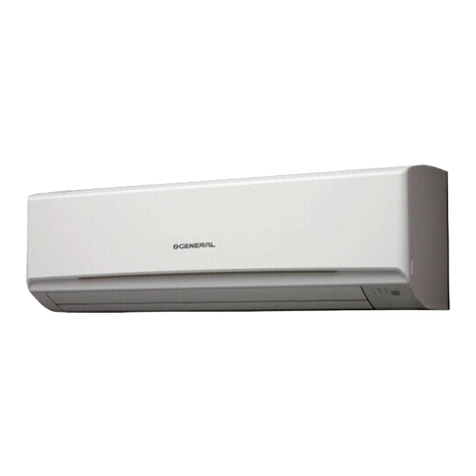
Acson AWM09J User manual

Wall Mounted Split Systems
AWM-J_(ii)
AWM09J/JR
AWM15J/JR
AWM20J/JR
AWM25J/JR
A5WM10J/JR
A5WM15J/JR
A5WM20J/JR
A5WM25J/JR
Models:

AWM-J_(ii) Table of Contents
Table of Contents
Nomenclature......................................................................................................................1
Indoor Unit .....................................................................................................................1
Outdoor Unit ..................................................................................................................1
Product Line-Up.............................................................................................................2
Application Information .....................................................................................................5
Operating Range ...........................................................................................................5
Refrigerant Circuit Diagram ...........................................................................................6
Installation Guideline ...................................................................................................12
Sound Data........................................................................................................................21
Sound Pressure Level .................................................................................................21
NC Curve.....................................................................................................................22
Engineering & Physical Data...........................................................................................25
Performance Data.............................................................................................................27
Calculation Steps.........................................................................................................27
Performance Tables.....................................................................................................31
Outline & Dimension ........................................................................................................55
Wiring Diagram .................................................................................................................57
Service & Maintenance ....................................................................................................63
Troubleshooting ...............................................................................................................65
Exploded View & Part List ...............................................................................................69
“Acson” is a registered trademark of Acson International. All rights reserved.
© 2011 Acson International. All rights reserved throughout the world.
Bulletin illustrations cover the general appearance of Acson International products at the time of publication.
We reserve the right to change design and construction specifications at any time without notice.
Supercedes : AWM-J-2010

Nomenclature AWM-J_(ii)
1
A 5 WM 20 J R – A C L A B
Brand
A: Acson
Refrigerant
“ ”: R22
4: R407C
5: R410A
Product Type
WM: Wall Mounted
CK : Ceiling Cassette
CC: Ceiling Concealed
CM: Ceiling Mounted
Size
10 : ≈10,000 Btu/h
15 : ≈15,000 Btu/h
20 : ≈20,000 Btu/h
25 : ≈25,000 Btu/h
Product series
G: G series
J: J series
Model
“ ”: Cooling Only
R: Heat Pump
Electrical Characteristics
A : 50Hz / 1Ph / 220-240V
F : 50Hz / 3Ph / 380-415V
Market Region
C: Ex
p
ort with CE Markin
g
Product Specification
Variation
B : Second Issue
Type of Air Filter
L: Saranet
Grille
A: Grille A
A 5 LC 20 C R – A C P O E
Brand
A: Acson
Product Type
LC: Single Split Condensing Unit
Product series
C: C Series
Model
“ ”: Cooling Only
R: Heat Pump
Product Specification
Variation
A: First Issue
E: Fifth issue
Electrical Characteristics
A : 50Hz / 1Ph / 220-240V
F : 50Hz / 3Ph / 380-415V
Market Region
C: Ex
p
ort with CE Markin
g
Compressor
P: Matsushita Compressor
M: Mitsubishi Compressor
Refrigerant
“ ”: R22
4: R407C
5: R410A
Specifications Variation
O: Standard Unit
Size
10 : ≈10,000 Btu/h
15 : ≈15,000 Btu/h
20 : ≈20,000 Btu/h
25 : ≈25,000 Btu/h
Nomenclature
Indoor
Outdoor

2
AWM-J_(ii) Product Line-Up
Indoor Unit
A5WM-J
A5WM
Nomenclature
Classification
PCB
Handset
Air Purification
Grille
Marking
Others
LGSN
G18
Saranet Filter
Bio Filter
B
CE
COOLING
ONLY
10J ACLBA X X X X X
15J ACLBA X X X X X
HEATPUMP
10JR ACLBA X X X X X
15JR ACLBA X X X X X
Product Line-Up
Indoor Unit
AWM-J
AWM
Nomenclature
Classification
Handset
PCB
Air Purification
Marking
Grille
Others
G18
LGSN
Saranet Filter
Bio Filter
CE
B
COOLING
09J ACLBA X X X X X
15J ACLBA X X X X X
20J ACLBA X X X X X
25J ACLBA X X X X X
HEATPUMP
09JR ACLBA X X X X X
15JR ACLBA X X X X X
20JR ACLBA X X X X X
25JR ACLBA X X X X X

3
Product Line-Up AWM-J_(ii)
Outdoor Unit
ALC
ALC
Nomenclature
Classification
PCB
Refrigerant
Control
FIN
Safety Devices
Compressor
Marking
Others
Cap Tube
EXV
Gold Fin
Blue Fin
Aluminium Fin
Contactor
HP
LP
Rotary
CE
Drain Elbow
Low Ambient Kit
COOLING
09C ACPOH X X X X
15 C ACPOH X X X X
20C ACPOD X X X X
25C ACPOD X X X X
HEATPUMP
09CR ACPOH X X X X X
15CR ACPOJ X X X X X
20CR ACPOD X X X X X
25CR ACPOD X X X X X
Outdoor Unit
A5LC
A5LC
Nomenclature
Classification
PCB
Refrigerant
Control
FIN
Safety Devices
Compressor
Marking
Others
Cap Tube
EXV
Gold Coated
Blue Coated
Bare
Contactor
HP
LP
Rotary
CE
Drain Elbow
Low Ambient Kit
COOLING ONLY
10CJ
ACPGG X X X X X
ACPOG X X X X
15CJ
ACPGG X X X X X
ACPOG X X X X
HEATPUMP
10CRJ ACPOG X X X X
15CRJ ACPOG X X X X

4
AWM-J_(ii) Product Line-Up
Indoor Unit
A5WM
A5WM
Nomenclature
Classification
PCB
Handset
Air Purification
Grille
Marking
Others
LGSN
GS02
Saranet Filter
Bio Filter + Titanium
Apatite Filter
B
CE
COOLING
ONLY
20J ACLBB X X X X X
25J ACLBB X X X X X
HEATPUMP
20JR ACLBB X X X X X
25JR ACLBB X X X X X
Outdoor Unit
A5LC
A5LC
Nomenclature
Classification
PCB
Refrigerant
Control
FIN
Safety Devices
Compressor
Marking
Others
Cap Tube
EXV
Gold Coated
Blue Coated
Bare Fin
Contactor
HP
LP
Rotary
CE
Drain Elbow
Low Ambient Kit
COOLING
ONLY
20CJ ACPOE X X X X X
25CJ ACPOE X X X X X
HEATPUMP
20CRJ ACPOE X X X X X X
25CRJ ACPOE X X X X X

5
Application Information AWM-J_(ii)
Application Information
Operating Range
Ensure the operating temperature is in allowable range.
Cooling only
Note :
Standard operating range.
With Low ambient kit. (Optional item)
Please refer to local dealer for unit of this specification.
Indoor temp. (°CDB)
Cooling
Outdoor temp. (°CDB)
Indoor temp. (°CWB)
Outdoor temp. (°CDB)
Indoor temp. (°CWB)
Heating
Outdoor temp. (°CWB)
-9
16 21
6
30
-5
19
35
14
46
23
Standard
point
Low ambient kit
18
-5
19
35
14
46
23
Low ambient kit
Standard
point
Standard
point
!Caution :
The use of your air conditioner
outside the range of working
temperature and humidity can
result in serious failure.
Heatpump

6
AWM-J_(ii) Application Information
Refrigerant Circuit Diagram
Model: AWM09J - ALC09C A5WM10J - A5LC10CJ
AWM15J - ALC15C A5WM15J - A5LC15CJ
70034 049971
Model: AWM20J - ALC20C

7
Application Information AWM-J_(ii)
Model: AWM25J - ALC25C
Model: AWM09JR - ALC09CR A5WM10JR - A5LC10CRJ
A5WM15JR - A5LC15CRJ
70034 023154

8
AWM-J_(ii) Application Information
Model: AWM20JR - ALC20CR
Model: AWM15JR - ALC15CR
70034 095236

9
Application Information AWM-J_(ii)
Model: A5WM20J – A5LC20CJ
Model: A5WM25J – A5LC25CJ

10
AWM-J_(ii) Application Information
Model: AWM25JR - ALC25CR
CHECK JOINT
COOLING & HEATING
CAP TUBE
Model: A5WM20JR – A5LC20CRJ
CHECK JOINT
HEATING CAP TUBE
COOLING & HEATING
CAP TUBE
CHECK VALVE

11
Application Information AWM-J_(ii)
Model: A5WM25JR – A5LC25CRJ
CHECK JOINT
COOLING & HEATING
CAP TUBE

12
AWM-J_(ii) Application Information
Installation Guideline
Safety Precautions
WARNING CAUTION
• Installation and maintenance should be performed
by qualified persons who are familiar with local code
and regulation, and experienced with this type of
appliance.
• All field wiring must be installed in accordance with the
national wiring regulation.
• Ensure that the rated voltage of the unit corresponds
to that of the name plate before commencing wiring
work according to the wiring diagram.
• The unit must be GROUNDED to prevent possible
hazard due to insulation failure.
• All electrical wiring must not touch the refrigerant
piping or any moving parts of the fan motors.
• Confirm that the unit has been switched OFF before
installing or servicing the unit.
• Disconnect from the main power supply before
servicing the air conditioner unit.
• DO NOT pull out the power cord when the power is
ON. This may cause serious electrical shocks which
may result in fire hazards.
• Keep the indoor and outdoor units, power cable and
transmission wiring, at least 1m from TVs and radios,
to prevent distorted pictures and static. {Depending on
the type and source of the electrical waves, static may
be heard even when more than 1m away}.
Please take note of the following important points
when installing.
• Do not install the unit where leakage of flammable
gas may occur.
If gas leaks and accumulates around the unit, it
may cause fire ignition.
• Ensure that drainage piping is connected properly.
If the drainage piping is not connected properly,
it may cause water leakage which will dampen
the furniture.
• Do not overcharge the unit.
This unit is factory pre-charged. Overcharge will
cause over-current or damage to the compressor.
• Ensure that the unit’s panel is closed after service
or installation.
Unsecured panels will cause the unit to operate
noisily.
• Sharp edges and coil surfaces are potential
locations which may cause injury hazards. Avoid
from being in contact with these places.
• Before turning off the power supply, set the remote
controller’s ON/OFF switch to the “OFF” position
to prevent the nuisance tripping of the unit. If this is
not done, the unit’s fans will start turning automatically
when power resumes, posing a hazard to service
personnel or the user.
• Do not operate any heating apparatus too close to the
air conditioner unit. This may cause the plastic panel to
melt or deform as a result of the excessive heat.
• Ensure the color of wires of the outdoor unit and
the terminal markings are same to the indoors
respectively.
• IMPORTANT : DO NOT INSTALL OR USE THE
• AIR CONDITIONER UNIT IN A LAUNDRY ROOM.
• Do not use joined and twisted wires for incoming
power supply.
NOTICE
Disposal requirements
Your air conditioning product is marked with this symbol. This means that electrical and electronic products
shall not be mixed with unsorted household waste.
Do not try to dismantle the system yourself: the dismantling of the air conditioning system, treatment of
the refrigerant, of oil and of other parts must be done by a qualified installer in accordance with relevant
local and national legislation. Air conditioners must be treated at a specialized treatment facility for re-use,
recycling and recovery. By ensuring this product is disposed of correctly, you will help to prevent potential
negative consequences for the environment and human health. Please contact the installer or local authority
for more information.
Batteries must be removed from the remote controller and disposed of separately in accordance with relevant
local and national legislation.

13
Application Information AWM-J_(ii)
Caution
Before installing the unit, ensure that the power supply matches the power requirement of the air conditioner.
Installation of Indoor Unit
Service Space
Install the indoor unit at a location with the following requirements
• Location is suitable for wiring, piping and drainage.
• No obstruction of air flow into and out of unit where cooler air can be evenly distributed.
• Ensure that air discharge is not short circuited with air intake.
• Ensure that wall is sufficiently strong, rigid, flat, perpendicular and vibration free.
• Where air filter cassette can be slided in or out easily.
• Where there is no danger of flammable gases.
• Where there is no direct sunlight on unit.
min. 50
(Space for
maintenance)
Air flow
(Indoor)
min. 50
(Space for
maintenance)
03.nim
rofecapS(
)ecnamrofrep
Required space
Installation Clearance
• Outdoor units must be installed such that there is no short circuit of the hot discharge air or obstruction to
smooth air flow. Select the coolest possible place where intake air should not be hotter than the outside
temperature (max. 45˚C).
ALL MODELS A B C D
Minimum Distance 300 mm 1000 mm 300 mm 500 mm
CAUTION : If the condensing unit is operated in an atmosphere containing oils (including machine oils), salt (coastal area),
sulphide gas (near hot spring, oil refinery plant), such substances may lead to failure of the unit.

14
AWM-J_(ii) Application Information
Cooling Unit (single phase)
COMP
N1
COMP
N
N
L
Outdoor Unit
Terminal Block
Indoor Unit
Terminal Block
There must be a double pole switch
with a minimum 3mm contact gap and
fuse/circuit breaker as recommended
in the fixed installation circuit.
Power Supply Cable
***
Outdoor coil sensor connection wire
(8m long) attached in the indoor unit
Model
Voltage range** 220V-240V/1Ph/50Hz +
Power supply cable size* mm
2
1.5 2.5
Number of wire 33
Interconnection cable size* mm
2
1.5 2.5
Number of wire 33
Recommended fuse A 15 20
A(5)WM20/25J
A(5)LC20/25C
A(5)WM09/10/15J
A(5)LC09/10/15C
Heat Pump Unit (single phase)
There must be a double pole switch
with a minimum 3mm contact gap and
fuse/circuit breaker as recommended in
the fixed installation circuit.
Outdoor Unit
Terminal Block
Indoor Unit
Terminal Block
Power Supply Cable
Outdoor coil sensor connection wire
(8m long) attached in the indoor unit
COMP
N1
OF
4WV
N
L
COMP
OF
4WV
N
Model
Voltage range** 220V-240V/1Ph/50Hz +
Power supply cable size* mm
2
1.5 2.5
Number of wire 33
Interconnection cable size* mm
2
1.5 2.5
Number of wire 33
Recommended fuse A 15 20
A(5)WM20/25JR
A(5)LC20/25CR
A(5)WM09/10/15JR
A(5)LC09/10/15CR

15
Application Information AWM-J_(ii)
Wiring
Electrical Connections
• Wiring regulations on wire diameters differ from country to country. Please refer to your LOCAL
ELECTRICAL CODES for field wiring rules. Be sure that installations comply with the rules and regulations.
General Precautions
• Ensure that the rated voltage of the unit corresponds to the name plate before carrying out proper wiring
according to the wiring diagram.
• Provide a power outlet to be used exclusively for each unit. A power supply disconnects and a circuit
breaker for over-current protection should be provided in the exclusive line.
• The unit must be GROUNDED to prevent possible hazards due to insulation failures.
• All wiring must be firmly connected.
• All wiring must not touch the hot refrigerant piping, compressor or any moving parts of fan motors.
Refrigerant Piping
Piping Length and Elevation
When the pipe length becomes too long, both the capacity and reliability drop. As the number of bends increases,
system piping resistance to the refrigerant flow increases, thus lowering the cooling capacity, and as the result
the compressor may become defective. Always choose the shortest path and follow the recommendation as
tabulated below:
Outdoor Unit
Indoor Unit
LH
Model
Indoor AWM09J/JR
A5WM10J/JR
AWM15J/JR
A5WM15J/JR
AWM20J/JR
A5WM20J/JR
AWM25J/JR
A5WM25J/JR
Outdoor ALC09C/CR
A5LC10C/CR
ALC15C/CR
A5LC15C/CR
ALC20C/CR
A5LC20C/CR
ALC25C/CR
A5LC25C/CR
Min. Allowable Length, m (L) 3 3 3 3
Max. Allowable Length, m (L) 12 12 15 15
Max. Allowable Height, m (H) 5 5 8 8
Liquid, mm/in 6.35 / 1/4 6.35 / 1/4 6.35 / 1/4 9.52 / 3/8
Suction, mm/in 9.52 / 3/8 12.70 / 1/2 15.87 / 5/8 15.87 / 5/8
* Be sure to add the proper amount of additional refrigerant. Failure to do so may result in reduced performance
Remark: The refrigerant pre-charged in the outdoor unit is for piping length up to 7.6m/25ft.

16
AWM-J_(ii) Application Information
Piping Works
• Do not use contaminated or damaged copper tubing. Do not remove plastic, rubber plugs and brass nuts
from the valves, fittings, tubings and coils until you are ready to connect suction or liquid line into valves or
fittings.
• If any brazing work is required, ensure that the nitrogen gas is passed through coil and joints while the
brazing work is being done. This will eliminate soot formation on the inside walls of the copper tubings.
• Cut the connection pipe with a pipe cutter.
Cutting copper tube
1/4t
• Remove burrs from cut edges of the pipes with remover. Hold the end of the pipe downwards to prevent
metal chips from entering the pipe.
Remove burr
• Insert the flare nuts, mounted on the connection parts of both the indoor unit and outdoor unit onto the
copper pipes.
• Flare the pipe with extra length above the flaring tool as shown in the table.
• The flared edge must be even and not cracked or scratched.
Ø Tube,
D (mm / in)
A (mm)
Imperial Die Rigid Die
6.35 / 1/4 1.3 0.7
9.52 / 3/8 1.6 1.0
12.70 / 1/2 1.9 1.3
15.88 / 5/8 2.2 1.7
19.05 / 3/4 2.5 2.0
Swaging block
Copper tube
Piping Connection to the Units
• Align the center of the piping and tighten the flare nut sufficiently with fingers.
• Finally tighten the flare nut with torque wrench unit the wrench clicks.
• When tightening the flare nut with torque wrench, ensure the direction for tightening follows the arrow on
the wrench.
Pipe Size (mm/in) Torque (Nm)
6.35 (1/4) 18
9.52 (3/8) 42
12.70 (1/2) 55
15.88 (5/8) 65
19.05 (3/4) 78
Indoor piping Flare nut
Flared tube
Fl
are
j
o
i
nt
Spanar Torque wrench

17
Application Information AWM-J_(ii)
Vacuuming and Charging
The pre-charged outdoor unit does not need any vacuuming or charging. However once it is connected, the
connecting pipe line and the indoor unit need to be vacuumed before releasing the R22/R407C/R410A from
the outdoor unit.
1. Open the service port core cap.
2. Connect pressure gauge to the service port.
3. Connect the line to vacuum pump. Open the charging manifold valve and turn the pump on. Vacuum to -0.1
MPa (-760mmHg) or lower. (Evacuation time varies by the pump but averagely in 1 hour).
Filter Dryer
(Mclecular-Sieve Type
Note : R22 - Nil
R410A - Nil
4. After evacuation, unscrew the spindle (diagram B) for the gas to run to indoor unit.
Additional Charge
• The refrigerant gas is charged in the outdoor unit and, if the piping length is 7.6m, additional charge of the
refrigerant after vacuuming is not necessary.
• When the piping length is more than 7.6m, additional refrigerant charge (g) per additional 1m length as
tabulated:
R22
Indoor AWM09/15J AWM09/15JR AWM20J AWM20JR AWM25J AWM25JR
Outdoor ALC09/15C ALC09/15CR ALC20C ALC20CR ALC25C ALC25CR
Additional Charge (g/m) 16 23 15 22 39 55
R410A
Indoor A5WM10/15J A5WM10/15JR A5WM20/25J A5WM20/25JR
Outdoor A5LC10/15C A5LC10/15CR A5LC20/25C A5LC20/25CR
Additional Charge [g/m] 9 16 11 16

18
AWM-J_(ii) Application Information
Diagram shows typical charging method:
(Mclecular-Sieve Type)
Note : R22 - Nil
R410A - Nil
Caution
• For R410A, avoid prolong exposure of an opened compressor, or the internal part of refrigerant piping to moist air.
The POE oil in the compressor and piping can absorb moisture from air.
Overall Checking
• Ensure the following, in particular:
1. The unit is mounted solidly and rigid in position.
2. Piping and connections are leak proof after charging.
3. Proper wiring has been done.
• Drainage check – pour some water into drain pan.
• Test run
1. Conduct a test run after water drainage test and gas leakage test.
2. Watch out for the following:
(a) Is the electric plug firmly inserted into the socket?
(b) Is there any abnormal sound from the unit?
(c) Is there any abnormal vibration with regard to the unit itself or piping?
(d) Is there smooth drainage of water?
• Check that:
1. Outdoor fan is running, with warm air blowing off the outdoor unit (cooling cycle).
2. Indoor blower is running and discharge cool air (cooling cycle).
3. Suction (low side) pressure is as per recommendations.
4. The remote controller has incorporated a 3 minutes delay in the circuit. Thus, it requires about 3 minutes
before the outdoor unit can start up.
Standard Operating Condition
Cooling only unit
Temperature Ts °C / °F Th °C / °F
Minimum indoor temperature 19.0 / 66.2 14.0 / 57.2
Maximum indoor temperature 32.0 / 89.6 23.0 / 73.4
Minimum outdoor temperature 19.4 / 66.9 -
Maximum outdoor temperature 46.0 / 114.8 -
Heat pump unit
Temperature Ts °C / °F Th °C / °F
Minimum indoor temperature 16.0 / 60.8 -
Maximum indoor temperature 30.0 / 86.0 -
Minimum outdoor temperature -8.0 / 17.6 -9.0 / 15.8
Maximum outdoor temperature 24.0 / 75.2 18.0 / 64.4
Ts : Dry bulb temperature Th : Wet bulb temperature
This manual suits for next models
15
Table of contents
Other Acson Air Conditioner manuals
Acson
Acson AWM 301 User manual
Acson
Acson A5WMX 10 GR User manual
Acson
Acson IM-FCU-0501-ACSON User manual

Acson
Acson ART 55 A User manual
Acson
Acson 5CEY15E User manual
Acson
Acson IM-CCXC-0506-ACSON User manual
Acson
Acson E series User manual
Acson
Acson AWM User manual
Acson
Acson AMSD-A Series User manual
Acson
Acson 5WMWS10GR User manual
Acson
Acson 5CEE Series User manual
Acson
Acson ACM 28 ER User manual
Acson
Acson 5CE 35E User manual
Acson
Acson A4LC 10 B User manual
Acson
Acson A5LCY 10DR User manual
Acson
Acson 5CCY10C/CR User manual
Acson
Acson C Series User manual
Acson
Acson AWM 25GR User manual
Acson
Acson ADB-B Series User manual
Acson
Acson ACM15E User manual
