Acson A5WMY-S Series User manual

Technical Manual
WALL MOUNTED
INVERTER SERIES
A5WMY-S

Table of Contents
i
Table of Contents
Nomenclature......................................................................................................................1
Indoor ............................................................................................................................1
Outdoor ..........................................................................................................................2
Product Line-Up .............................................................................................................3
Application Information .....................................................................................................5
Operating Range ...........................................................................................................5
Refrigerant Circuit Diagrams .........................................................................................6
Installation Guideline .....................................................................................................7
Sound Data ........................................................................................................................ 11
Sound Pressure Level ................................................................................................ 11
NC Curve .....................................................................................................................12
Engineering & Physical Data ...........................................................................................14
Performance Data .............................................................................................................15
Calculation Steps .........................................................................................................15
Performance Tables .....................................................................................................18
Outline & Dimension ........................................................................................................22
Wiring Diagram .................................................................................................................25
Service & Maintenance ....................................................................................................27
Troubleshooting ...............................................................................................................29

Nomenclature
1
Nomenclature
Indoor
WM 10 S A LAM IY5A
Revision
A : First Revision
B : Second Revision
Specifi cation
L : White + Silver Grille
I : White Grille
Specifi cation
I : Plasma
L : Bare
Country
M : Malaysia
Series
S : S series
Capacity*
10 : 10000 Btu/hr
Type
Y : Inverter
Power Supply
A : 220 - 240V / 1 Phase / 50 Hz
Model
WM : Wall Mounted
Refrigerant
5 : R410A
Brand
A : Acson
Remark:
* : Capacity value under Nomenclature is an indication.
Please refer to Engineering and Physical Data for exact capacity value.

Nomenclature
2
Outdoor
LC 10 F A OCM DY5A
Revision
A : First Revision
B : Second Revision
C : Third Revision
Specifi cation
O : Bare Fin
I : Gold Fin
Compressor
D : Daikin
Country
M : Malaysia
Series
F : F series
C : C series
Capacity*
10 : 10000 Btu/hr
Type
Y : Inverter
Power Supply
A : 220 - 240V / 1 Phase / 50 Hz
Model
LC : Single split condensing unit
Refrigerant
5 : R410A
Brand
A : Acson
Remark:
* : Capacity value under Nomenclature is an indication.
Please refer to Engineering and Physical Data for exact capacity value.
Nomenclature
3
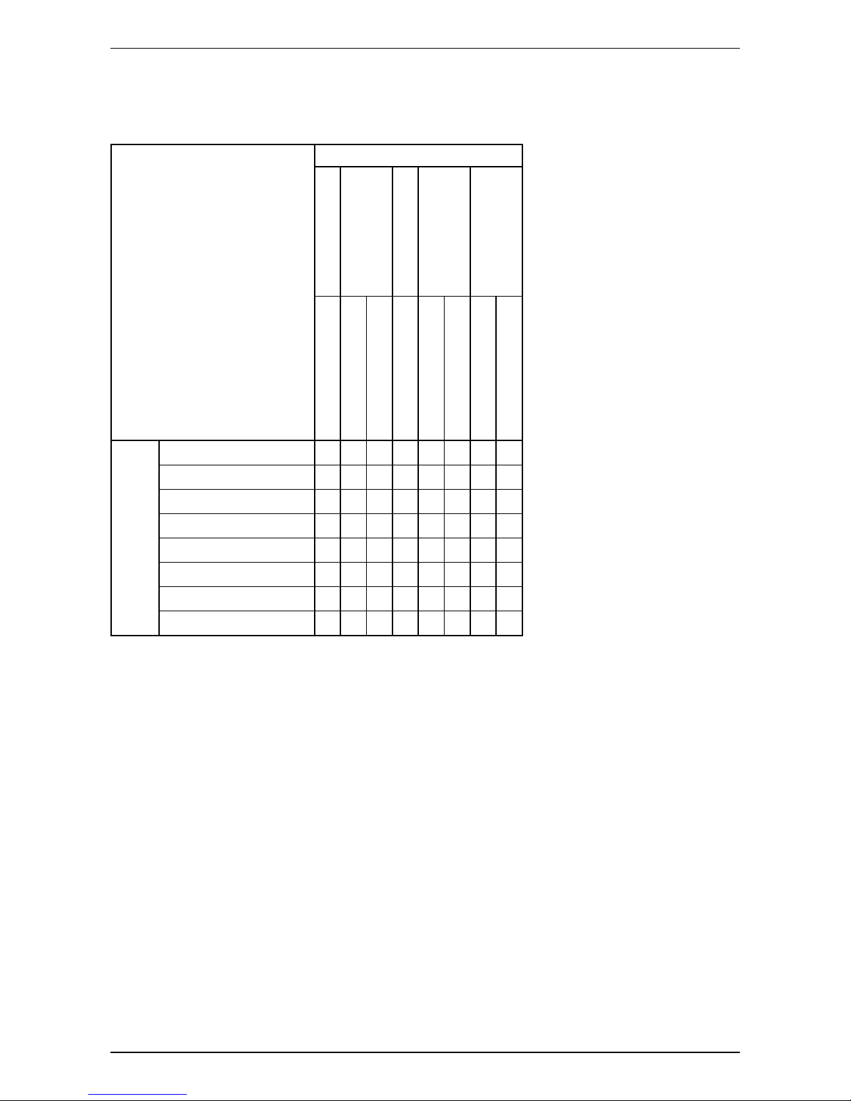
Product Line-Up
Indoor Unit
A5WMY-S
Nomenclature
Classifi cation
Handset
PCB
Air Purifi cation
Specifi cation
Grille
GS02
W2_03_EM
W_204_BM
Saranet Filter
Plasma
Bare
White + Silver
White
COOLING
A5WMY10S-AMILA-R X X X X X
A5WMY10S-AMLIA-R X X X X X
A5WMY15S-AMILA-R X X X X X
A5WMY15S-AMLIA-R X X X X X
A5WMY20S-AMILA-R X X X X X
A5WMY20S-AMLIA-R X X X X X
A5WMY25S-AMILA-R X X X X X
A5WMY25S-AMLIA-R X X X X X
Nomenclature
4
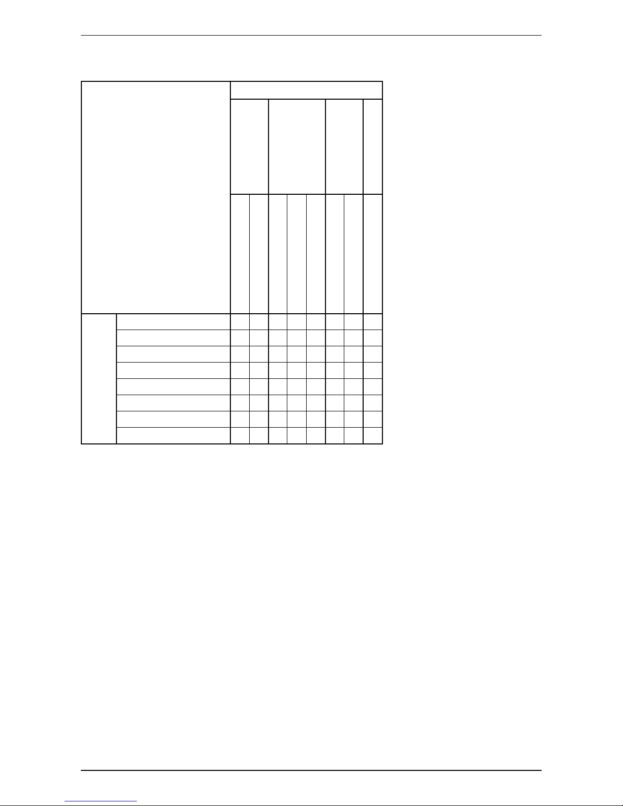
Outdoor Unit
A5LCY-F/C
Nomenclature
Classifi cation
Refrigerant Control
PCB
Fin
Compressor
Cap Tube
EXV
Main PCB (ADGPA31)
Main PCB (2P273854)
Filter PCB (3P273862)
Hydrophilic (Gold)
Bare Aluminium
Swing
COOLING
A5LCY10F-AMDOC-R X X X X
A5LCY10F-AMDIC-R X X X X
A5LCY15F-AMDOC-R X X X X
A5LCY15F-AMDIC-R X X X X
A5LCY20C-AMDOC-R X X X X X
A5LCY20C-AMDIC-R X X X X X
A5LCY25C-AMDOC-R X X X X X
A5LCY25C-AMDIC-R X X X X X

5
Application Information
Application Information
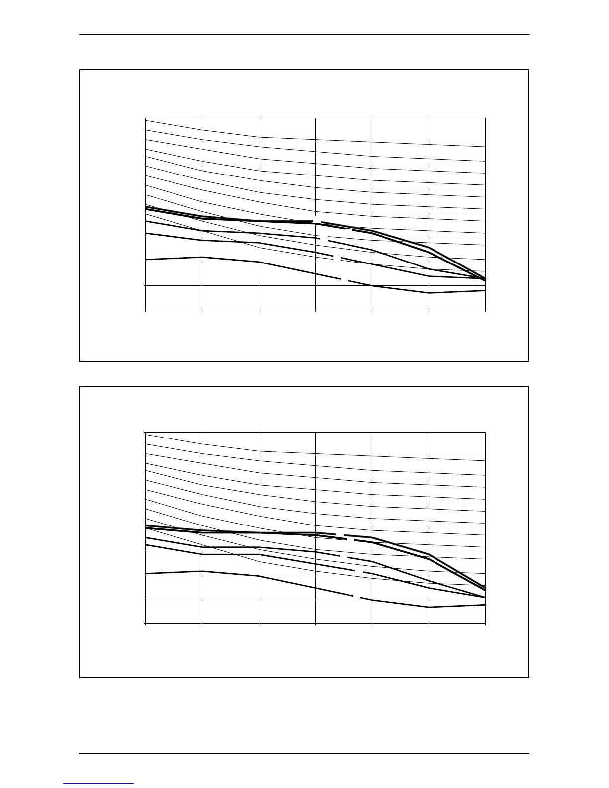
Operating Range
Ensure the operating temperature is in allowable range.
Cooling
A5WMY10/15S-AMLIA/AMILA-R - A5LCY10/15F-AMDOC/AMDIC-R
A5WMY20/25S-AMLIA/AMILA-R - A5LCY20/25C-AMDOC/AMDIC-R
DB: Dry bulb WB: Wet bulb
50
OUTDOOR TEMP. (°CDB)
INDOOR TEMP. (°CWB)
46
43
40
30
20
10
0
10 14 15 19 20 23
50
OUTDOOR TEMP. (°CDB)
INDOOR TEMP. (°CWB)
46
43
40
30
20
10
010 14 15 19 20 23 25
-10
25
-20
20/25S10/15S

6
Application Information
Refrigerant Circuit Diagrams
Model: A5WMY10/15S-AMLIA/AMILA-R - A5LCY10/15F-AMDOC/AMDIC-R /
A5WMY20/25S-AMLIA/AMILA-R - A5LCY20/25C-AMDOC/AMDIC-R
PIPING
GAS
3 WAY
VALVE
MUFFLER
COOLING OPERATION
PIPING
LIQUID
RETURN AIR SENSOR
HEAT EXCHANGER
(INDOOR UNIT)
PIPE TEMPERATURE SENSOR
DISCHARGE
ACCUMULATOR
COMPRESSOR
STRAINER
OUTDOOR UNIT
INDOOR UNIT
3 WAY
VALVE
ELECTRONIC EXPANSION
VALVE
PIPE TEMPERATURE SENSOR
RETURN AIR SENSOR
HEAT EXCHANGER
(OUTDOOR UNIT)

7
Application Information
Installation Guideline
Sharp edges and coil surfaces are potential injury hazard. Avoid from contact with them.
Installation Diagram
Front panel
50mm or more from walls
(on both sides)
75mm or more from ceiling
M4 x 12L
Air filter
Service lid
Ŷ
Opening service lid
Service lid is opening/
closing type.
Ŷ
Opening method
1) Remove the service lid
screws.
2) Pull out the service lid
diagonally down in the
direction of the arrow.
3) Pull down.
500mm from wall
Indoor unit
Outdoor unit
Wrap the insulation pipe with the
finishing tape from bottom to top.
Cut thermal insulation pipe to an
appropriate length and wrap it with
tape, making sure that no gap is left
in the insulation pipe’s cut line.
Caulk pipe
hole gap
with putty.
8
Application Information
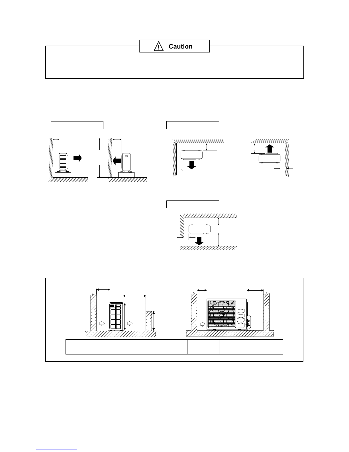
Outdoor Clearance
If the condensing unit is operated in an atmosphere containing oils (including machine
oils), salt (coastal area), sulphide gas (near hot spring, oil refi nery plant), such as
substances may lead to failure of the unit.
• Where a wall or order obstacle is in the path of outdoor unit’s intake or exhaust airfl ow, follow the
installation guidelines below.
• For any of the below installation patterns, the wall height on the exhaust side should be 1200mm or less.
Model: A5LCY10/15F-AMDOC/AMDIC-R
Wall facing one side Wall facing two side
More than 50
Side View Top View
Top View
Unit : mm
More than 50
More than 150
More than 50 More than 300
More than 50
More than 100
More
than 100
1200 or
less
More than 150
Wall facing three side
Model: A5LCY20/25C-AMDOC/AMDIC-R
ALL MODELS
Minimum Distance
A
300 mm
B
1000 mm
C
300 mm
D
500 mm
Obstacle
Return air
Service access
DC
Obstacle
Return air
Discharge air
A
Obstacle
Obstacle
B
H/2
H

9
Application Information
Cable Size
Model Indoor Unit A5WMY10/15S A5WMY20/25S
Outdoor A5LCY10/15F A5LCY20/25C
Power supply cable size
Number of wire
mm21.5
3
2.5
3
Interconnection cable size
Number of wire
mm21.5
4
2.5
4
Recommended fuse A 15 20
10
Application Information
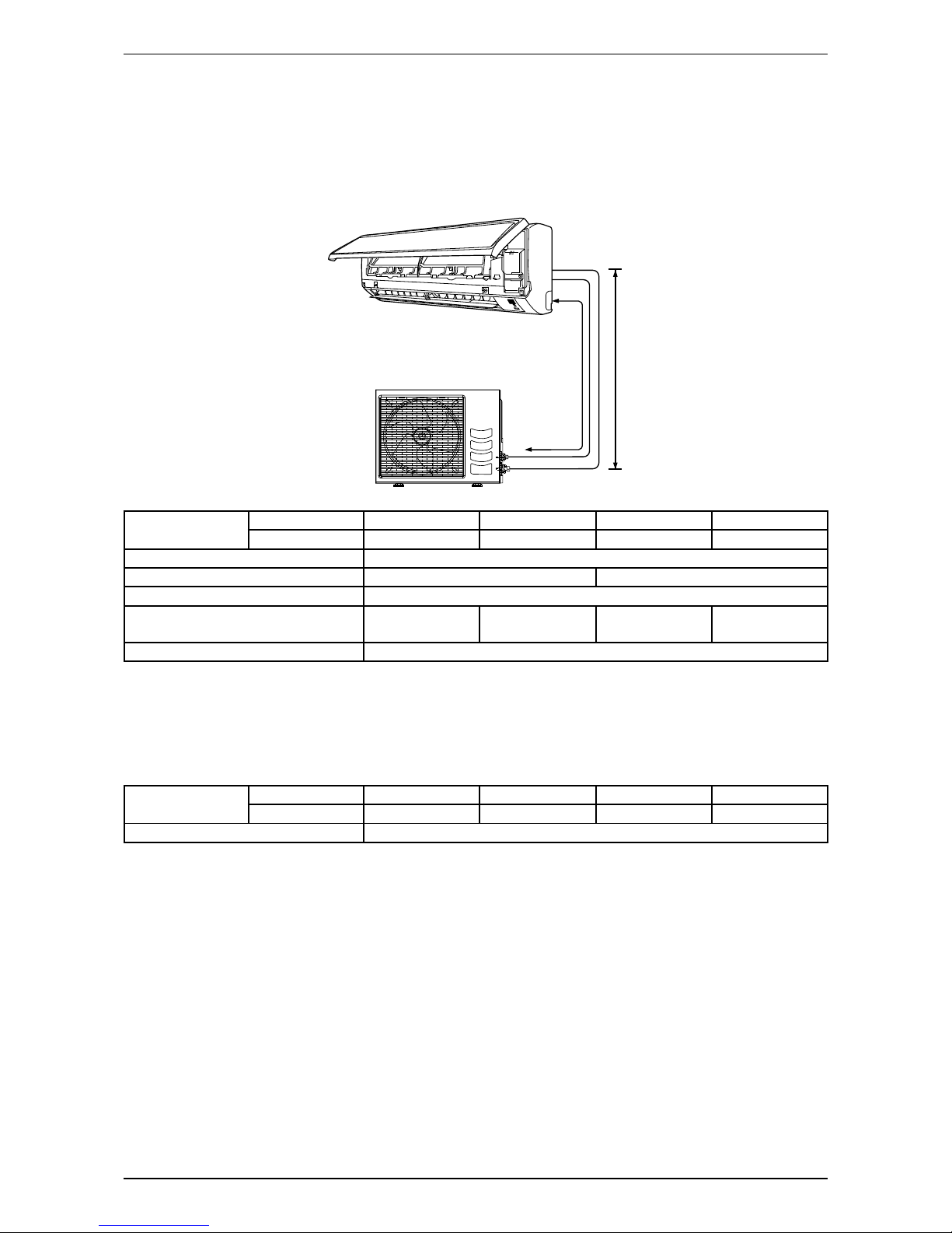
Refrigerant Piping
Piping Length and Elevation
When the pipe length becomes too long, both the capacity and reliability drop. As the number of bends increases,
system piping resistance to the refrigerant fl ow increases, thus lowering the cooling capacity, and as the result
the compressor may become defective. Always choose the shortest path and follow the recommendation as
tabulated below:
Outdoor Unit
LE
Indoor Unit
Model Indoor A5WMY10S A5WMY15S A5WMY20S A5WMY25S
Outdoor A5LCY10F A5LCY15F A5LCY20C A5LCY25C
Min. Allowable Length (L), m 3
Max. Allowable Length (L), m 20 30
Max. Allowable Elevation (E), m 10
Gas Pipe Size, mm/(in) 9.52
(3/8”)
12.70
(1/2”)
12.70
(1/2”)
15.88
(5/8”)
Liquid Pipe Size, mm/(in) 6.35 (1/4”)
Additional Charge
• The refrigerant gas is charged in the outdoor unit and, if the piping length is 7.5m, additional charge of the
refrigerant after vacuuming is not necessary.
• When the piping length is more than 7.5m, additional refrigerant charge (g) per additional 1m length as
tabulated:
Model Indoor A5WMY10S A5WMY15S A5WMY20S A5WMY25S
Outdoor A5LCY10F A5LCY15F A5LCY20C A5LCY25C
Additional charge [g/m] 20
Example:
A5WMY10S & A5LCY10F with 15m piping length, additional piping length is 7.5m. Thus,
Additional charge = 7.5m x [20g/m]
= 150 [g]

11
Sound Data
Sound Data
Sound Pressure Level
Model Speed
1/1 Octave A-weighted Sound Pressure Level
(dB, ref 20μPa) Overall
(dBA)
Noise
Criteria
125Hz 250Hz 500Hz 1kHz 2kHz 4kHz 8kHz
A5WMY10S-
AMLIA/
AMILA-R
Turbo 43 39 37 37 33 26 13 41 36
Hi 42 38 37 36 32 24 12 40 35
Me 37 33 32 30 25 17 13 34 29
Lo 32 29 28 24 19 14 13 29 22
Quiet 21 22 20 15 10 7 8 21 -
A5WMY15S-
AMLIA/
AMILA-R
Turbo 41 39 38 38 36 29 15 42 37
Hi 40 38 38 37 34 27 14 41 36
Me 36 32 32 30 26 18 11 34 29
Lo 33 29 29 25 21 15 11 30 23
Quiet 24 22 21 17 11 7 7 22 -
A5WMY20S-
AMLIA/
AMILA-R
Turbo 39 41 40 40 37 29 16 44 39
Hi 35 37 37 36 32 25 12 40 35
Me 34 36 36 34 29 22 11 38 33
Lo 30 34 33 31 26 18 10 35 30
Quiet 28 32 30 28 22 14 10 32 26
A5WMY25S-
AMLIA/
AMILA-R
Turbo 42 44 43 42 40 35 20 46 41
Hi 39 41 40 38 36 31 16 43 37
Me 37 39 38 37 33 28 13 41 36
Lo 33 36 35 33 28 22 11 37 32
Quiet 28 33 32 28 23 17 9 33 26
Model Measuring Location
A5WMY10S-AMLIA/
AMILA-R
A5WMY15S-AMLIA/
AMILA-R
A5WMY20S-AMLIA/
AMILA-R
A5WMY25S-AMLIA/
AMILA-R
Microphone
1.0m
0.8m
Standard : JIS C 9612
12
Sound Data
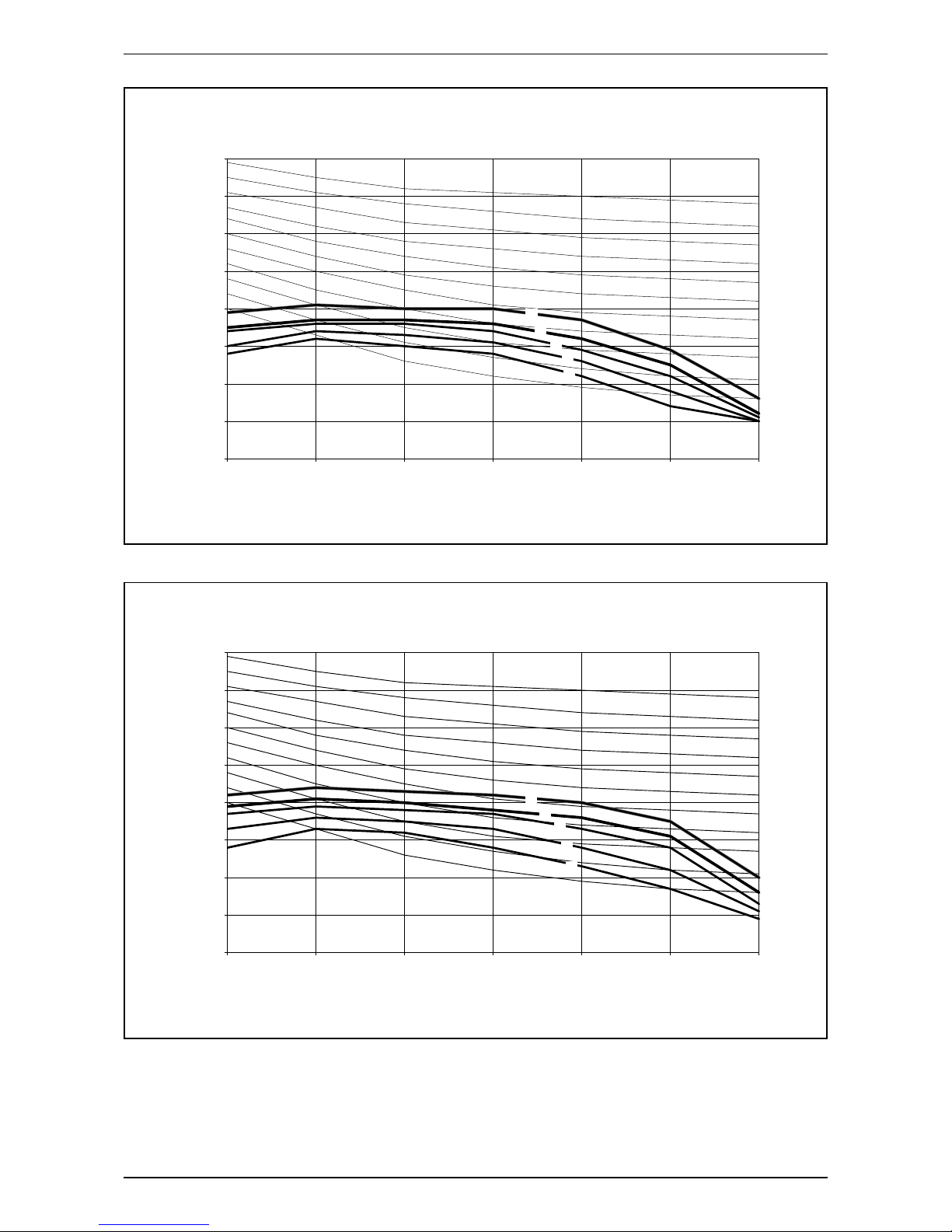
NC Curve
0
10
20
30
40
50
60
70
80
125 250 500 100020004000800
0
Sound pressure level (dB, ref 20μPa)
Octave-band frequency (Hz)
NC-20
NC-30
NC-25
NC-35
NC-40
NC-45
NC-50
NC-55
NC-65
NC-60
NC-70
T
H
M
L
Q
A5WMY10S-AMLIA/AMILA-R
0
10
20
30
40
50
60
70
80
125 250 500 1000 2000 4000 8000
Sound pressure level (dB, ref 20μPa)
Octave-band frequency (Hz)
NC-20
NC-30
NC-25
NC-35
NC-40
NC-45
NC-50
NC-55
NC-65
NC-60
NC-70
T
H
M
L
Q
A5WMY15S-AMLIA/AMILA-R
13
Sound Data
0
10
20
30
40
50
60
70
80
125 250 500 1000 2000 4000 8000
Sound pressure level (dB, ref 20μPa)
Octave-band frequency (Hz)
NC-20
NC-30
NC-25
NC-35
NC-40
NC-45
NC-50
NC-55
NC-65
NC-60
NC-70
T
H
M
L
Q
A5WMY20S-AMLIA/AMILA-R
0
10
20
30
40
50
60
70
80
125 250 500 1000 2000 4000 8000
Sound pressure level (dB, ref 20μPa)
Octave-band frequency (Hz)
NC-20
NC-30
NC-25
NC-35
NC-40
NC-45
NC-50
NC-55
NC-65
NC-60
NC-70
T
H
M
L
Q
A5WMY25S-AMLIA/AMILA-R

14
Engineering & Physical Data
Engineering & Physical Data
Engineering Data - R410A MODEL (Cooling Only)
MODEL
INDOOR UNIT A5WMY10S-AMLIA-R
A5WMY10S-AMILA-R
A5WMY15S-AMLIA-R
A5WMY15S-AMILA-R
A5WMY20S-AMLIA-R
A5WMY20S-AMILA-R
A5WMY25S-AMLIA-R
A5WMY25S-AMILA-R
OUTDOOR UNIT A5LCY10F-AMDOC-R
A5LCY10F-AMDIC-R
A5LCY15F-AMDOC-R
A5LCY15F-AMDIC-R
A5LCY20C-AMDOC-R
A5LCY20C-AMDIC-R
A5LCY25C-AMDOC-R
A5LCY25C-AMDIC-R
NOMINAL COOLING CAPACITY (MIN-MAX) Btu/h 9100 (4400-10200) 12100 (4400-13000) 18500 (4700-21200) 21500 (5800-23000)
W2670 (1290-2990) 3550 (1290-3810) 5420 (1400-6210) 6300 (1700-6740)
NOMINAL TOTAL INPUT POWER W 780 1075 1600 1870
NOMINAL RUNNING CURRENT A 3.49 4.82 7.11 8.30
EER Btu/h/W 11.67 11.26 11.56 11.50
W/W 3.42 3.30 3.39 3.37
REFRIGERANT CHARGE kg 0.74 1.00 1.25 1.45
POWER SOURCE V/Ph/Hz 220-240/1/50 220-240/1/50 220-240/1/50 220-240/1/50
REFRIGERANT TYPE R410A R410A R410A R410A
INDOOR UNIT
CONTROL AIR DISCHARGE AUTO LOUVER (UP & DOWN) & MANUAL GRILLE (LEFT & RIGHT)
OPERATION WIRELESS REMOTE CONTROL
AIR FLOW
TURBO l/s / CFM 178 / 378 185 / 392 273/578 332/703
HIGH l/s / CFM 163 / 345 169 / 358 250/529 309/654
MEDIUM l/s / CFM 128 / 272 133 / 282 222/471 276/585
LOW l/s / CFM 102 / 215 110 / 232 197/418 239/507
SILENT l/s / CFM 86 / 182 86 / 182 177/374 206/437
SOUND PRESSURE LEVEL (T/H/M/L/Q) dBA 41 / 40 / 34 / 29 / 21 42 / 41 / 34 / 30 / 22 44/40/38/35/32 46/43/41/37/33
UNIT DIMENSION HEIGHT X WIDTH X DEPTH mm 288 X 859 X 209 288 X 859 X 209 310 X 1124 X 237 310 X 1124 X 237
PACKING DIMENSION HEIGHT X WIDTH X DEPTH mm 367 X 970 X 303 367 X 970 X 303 400 X 1252 X 333 400 X 1252 X 333
UNIT WEIGHT kg 9 9 14 14
CONDENSATE DRAIN SIZE mm 19.05 19.05 19.05 19.05
FAN TYPE CROSS FLOW CROSS FLOW CROSS FLOW CROSS FLOW
DRIVE DIRECT DIRECT DIRECT DIRECT
FAN MOTOR
TYPE PERMANENT SPLIT CAPACITOR DIRECT CURRENT
INDEX OF PROTECTION (IP) 44 44 20 20
INSULATION GRADE EEEE
RATED INPUT POWER W 37 42 37 63
RATED RUNNING CURRENT A 0.19 0.21 0.32 0.56
MOTOR OUTPUT W 18 18 40 40
POLES 4488
COIL
TUBE MATERIAL COPPER COPPER COPPER COPPER
DIAMETER mm 7777
FIN
MATERIAL ALUMINIUM ALUMINIUM ALUMINIUM ALUMINIUM
FACE AREA m20.18 0.18 0.29 0.29
ROW 2222
AIR QUALITY FILTER TYPE SARANET SARANET SARANET SARANET
QUANTITY pc 2222
CASING COLOUR WHITE WHITE WHITE WHITE
OUTDOOR UNIT
AIR FLOW l/s / CFM 401 / 850 345 / 730 798 / 1690 848 / 1796
SOUND PRESSURE LEVEL dBA 45 46 (47) 51 51
UNIT DIMENSION HEIGHT X WIDTH X DEPTH mm 550 x 658 x 273 550 x 658 x 273 654 x 855 x 328 756 x 855 x 328
PACKING DIMENSION HEIGHT X WIDTH X DEPTH mm 580 x 775 x 355 580 x 775 x 355 693 x 990 x 415 793 x 990 x 415
UNIT WEIGHT kg 24 26 37 44
PIPE
CONNECTION
TYPE FLARE VALVE FLARE VALVE FLARE VALVE FLARE VALVE
SIZE LIQUID mm 6.35 6.35 6.35 6.35
GAS mm 9.52 12.70 12.70 15.87
FAN TYPE PROPELLER PROPELLER PROPELLER PROPELLER
DRIVE DIRECT DIRECT DIRECT DIRECT
PIPE LENGTH PRE-CHARGED m 7.5 7.5 7.5 7.5
MAXIMUM m 20 20 30 30
FAN MOTOR
TYPE DIRECT CURRENT
QUANTITY 1111
INDEX OF PROTECTION (IP) 24 23 23 23
INSULATION GRADE CLASS E CLASS E CLASS E CLASS E
RATED INPUT POWER W 22 24 86 80
RATED RUNNING CURRENT A 0.31 0.34 0.90 0.77
MOTOR OUTPUT W 41 41 61 61
POLES 8888
COMPRESSOR
TYPE HERMETIC SWING HERMETIC SWING HERMETIC SWING HERMETIC SWING
OIL TYPE DAPHNE FVC50K
(Ether Oil)
DAPHNE FVC50K
(Ether Oil)
DAPHNE FVC50K
(Ether Oil)
DAPHNE FVC50K
(Ether Oil)
COIL
TUBE MATERIAL COPPER COPPER COPPER COPPER
DIAMETER mm 7777
FIN
MATERIAL ALUMINIUM ALUMINIUM ALUMINIUM ALUMINIUM
FACE AREA m20.33 0.32 0.62 0.62
ROW 1222
CASING COLOUR IVORY WHITE
1) ALL UNITS ARE BEING TESTED AND COMPLY TO ISO 5151 (NON-DUCTED UNIT) OR ISO 13253 (DUCTED UNIT).
2) ALL SPECIFICATIONS ARE SUBJECTED TO CHANGE BY THE MANUFACTURER WITHOUT PRIOR NOTICE.
COOLING
INDOOR: 27°C DB / 19°C WB
OUTDOOR: 35°C DB / 24°C WB

15
Performance Data
Performance Data
Calculation Steps
Interpolation method can be used to get the total cooling capacity, TC and sensible cooling capacity, SC
and power input, PI at those temperatures which are not stated out in the table. Extrapolation method is not
allowed to be used.
Example:
AFR
(CFM) EWB EDB
Outdoor temperature
19°C 25°C 30°C 35°C 40°C 46°C
TC SC PI TC SC PI TC SC PI TC SC PI TC SC PI TC SC PI
195
16°C
21°C 2.02 1.54 0.49 1.95 1.50 0.53 1.87 1.46 0.58 1.80 1.42 0.63 1.65 1.32 0.68 1.52 1.24 0.75
24°C 2.02 1.84 0.49 1.95 1.80 0.53 1.88 1.76 0.58 1.80 1.71 0.63 1.66 1.60 0.68 1.53 1.51 0.75
27°C 2.04 2.04 0.49 1.97 1.97 0.54 1.90 1.90 0.58 1.83 1.83 0.63 1.69 1.69 0.68 1.57 1.57 0.75
30°C 2.10 2.10 0.50 2.04 2.04 0.54 1.98 1.98 0.58 1.91 1.91 0.63 1.77 1.77 0.69 1.66 1.66 0.76
19°C
24°C 2.23 1.44 0.50 2.15 1.40 0.54 2.07 1.36 0.59 1.99 1.32 0.64 1.83 1.23 0.69 1.69 1.16 0.76
27°C 2.23 1.64 0.50 2.15 1.61 0.54 2.07 1.57 0.59 1.99 1.53 0.64 1.83 1.43 0.69 1.69 1.36 0.76
30°C 2.23 2.03 0.50 2.15 1.99 0.54 2.08 1.94 0.59 2.00 1.89 0.64 1.84 1.77 0.69 1.71 1.68 0.76
33°C 2.26 2.26 0.50 2.18 2.18 0.54 2.11 2.11 0.59 2.04 2.04 0.64 1.89 1.89 0.70 1.77 1.77 0.77
22°C
27°C 2.45 1.41 0.51 2.36 1.37 0.55 2.28 1.34 0.60 2.19 1.30 0.65 2.01 1.21 0.71 1.86 1.14 0.78
30°C 2.45 1.71 0.51 2.36 1.68 0.55 2.28 1.64 0.60 2.19 1.60 0.65 2.01 1.50 0.71 1.86 1.42 0.78
33°C 2.45 2.00 0.51 2.37 1.96 0.55 2.28 1.92 0.60 2.19 1.88 0.65 2.02 1.77 0.71 1.87 1.68 0.78
36°C 2.46 2.27 0.51 2.38 2.22 0.55 2.29 2.18 0.60 2.21 2.13 0.65 2.04 2.00 0.71 1.90 1.89 0.78
Solution:
Based on the Performance Table,
1. Refer to the Indoor DB column,
- 25°C is located between 24°C & 27°C for 16°C WB.
- 25°C is located between 24°C & 27°C for 19°C WB.
- Thus, Interpolation needs to be applied.
2. Refer to the Indoor WB column,
- 17°C is located between 16°C & 19°C for 25°C DB.
- Thus, Interpolation needs to be applied.
3. Refer to the Outdoor DB column,
- 37°C is located between 35°C & 40°C.
- Thus, Interpolation needs to be applied.
1st Step
Interpolation of Indoor WB
Find TC, SC & PI
(a) Indoor: 25°C DB, 16°C WB
Outdoor: 35°C DB
(b) Indoor: 25°C DB, 19°C WB
Outdoor: 35°C DB
(c) Indoor: 25°C DB, 16°C WB
Outdoor: 40°C DB
(d) Indoor: 25°C DB, 19°C WB
Outdoor: 40°C DB
2nd Step
Interpolation of Indoor DB
Find TC, SC & PI
(a) Indoor: 25°C DB, 17°C WB
Outdoor: 35°C DB
(b) Indoor: 25°C DB, 17°C WB
Outdoor: 40°C DB
3rd Step
Interpolation of Outdoor DB
Find TC, SC & PI
(a) Indoor: 25°C DB, 17°C WB
Outdoor: 37°C DB

16
Performance Data
Details of Calculation:
1st Step:
To obtain the TC, SC & PI for
(a) Indoor Condition: 25°C DB, 16°C WB
Outdoor Condition: 35°C DB
EWB EDB
Outdoor temperature
35°C
TC SC PI
16
24 1.80 1.71 0.63
25 x1y1z1
27 1.83 1.83 0.63
By Interpolation Method
25°C – 24°C =x1 – 1.80kW
27°C – 24°C 1.83kW – 1.80kW
x1 = 1.81kW
Similarly,
y1 = 1.75kW
z1 = 0.63kW
(b) Indoor Condition: 25°C DB, 19°C WB
Outdoor Condition: 35°C DB
EWB EDB
Outdoor temperature
35°C
TC SC PI
19
24 1.99 1.32 0.64
25 x2y2z2
27 1.99 1.53 0.64
By Interpolation Method
25°C – 24°C =x2 – 1.99kW
27°C – 24°C 1.99kW – 1.99kW
x2 = 1.99kW
Similarly,
y2 = 1.39kW
z2 = 0.64kW
Repeat the same process for (c) & (d) in 1st Step
(c) x3 = 1.69 kW; y3 = 1.63 kW; z3 = 0.68 kW
(d) x4 = 1.83 W; y4 = 1.30 kW; z4 = 0.69 kW
2nd Step:
To obtain the TC, SC & PI for
(a) Indoor Condition: 25°C DB, 17°C WB
Outdoor Condition: 35°C DB
EWB EDB
Outdoor temperature
35°C
TC SC PI
16
25
1.81 1.75 0.63
17 x5y5z5
19 1.99 1.39 0.64
By Interpolation Method
17°C – 16°C =x5 – 1.81kW
19°C – 16°C 1.99kW – 1.81kW
x5 = 1.87kW
Similarly,
y5 = 1.63kW
z5 =0.63kW
Repeat the same process for (b) in 2nd Step
(c) x6 = 1.74 kW; y6 = 1.52 kW; z6 = 0.68 kW

17
Performance Data
3rd Step:
To obtain the TC, SC & PI for
(a) Indoor Condition: 25°C DB, 17°C WB
Outdoor Condition: 37°C DB
EWB EDB
Outdoor temperature
35°C 37°C 40°C
TC SC PI TC SC PI TC SC PI
25 17 1.87 1.63 0.63 x y z 1.74 1.52 0.68
By Interpolation Method
37°C – 35°C =x – 1.87kW
40°C – 35°C 1.74kW – 1.87kW
x = 1.82kW
Similarly,
y = 1.59kW
z = 0.65kW
18
Performance Data
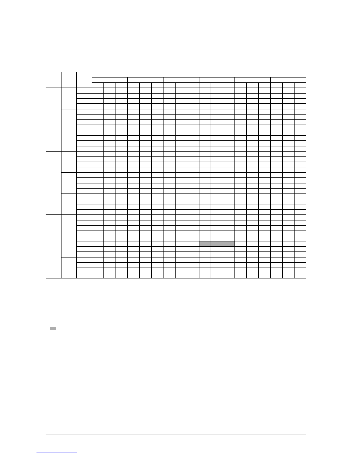
Performance Tables
R410A Cooling Only
Model: A5WMY10S-AMLIA/AMILA-R - A5LCY10F-AMDOC/AMDIC-R
Cooling Mode
AFR
(CFM) EWB EDB
Outdoor temperature
19°C 25°C 30°C 35°C 40°C 46°C
TC SC PI TC SC PI TC SC PI TC SC PI TC SC PI TC SC PI
215
16°C
21°C 2.52 2.09 0.59 2.43 2.03 0.64 2.34 1.98 0.69 2.24 1.92 0.75 2.06 1.79 0.82 1.90 1.68 0.90
24°C 2.52 2.50 0.59 2.43 2.43 0.64 2.34 2.34 0.69 2.25 2.25 0.75 2.06 2.06 0.82 1.91 1.91 0.90
27°C 2.54 2.54 0.59 2.46 2.46 0.64 2.37 2.37 0.70 2.28 2.28 0.75 2.10 2.10 0.82 1.96 1.96 0.90
30°C 2.62 2.62 0.60 2.54 2.54 0.65 2.47 2.47 0.70 2.39 2.39 0.76 2.21 2.21 0.83 2.07 2.07 0.91
19°C
24°C 2.78 1.95 0.60 2.68 1.90 0.65 2.58 1.85 0.71 2.48 1.80 0.77 2.28 1.67 0.83 2.11 1.58 0.92
27°C 2.78 2.23 0.60 2.68 2.18 0.65 2.58 2.13 0.71 2.48 2.08 0.77 2.28 1.94 0.83 2.11 1.84 0.92
30°C 2.78 2.75 0.60 2.69 2.69 0.65 2.59 2.59 0.71 2.49 2.49 0.77 2.30 2.30 0.83 2.13 2.13 0.92
33°C 2.81 2.81 0.60 2.72 2.72 0.65 2.63 2.63 0.71 2.55 2.55 0.77 2.35 2.35 0.84 2.20 2.20 0.92
22°C
27°C 3.05 1.91 0.61 2.95 1.86 0.66 2.84 1.82 0.72 2.73 1.77 0.78 2.51 1.65 0.85 2.32 1.55 0.93
30°C 3.05 2.33 0.61 2.95 2.28 0.66 2.84 2.22 0.72 2.73 2.17 0.78 2.51 2.03 0.85 2.32 1.93 0.93
33°C 3.06 2.72 0.61 2.95 2.66 0.66 2.84 2.61 0.72 2.73 2.56 0.78 2.51 2.40 0.85 2.33 2.28 0.93
36°C 3.07 3.07 0.61 2.96 2.96 0.66 2.86 2.86 0.72 2.76 2.76 0.78 2.54 2.54 0.85 2.36 2.36 0.94
272
16°C
21°C 2.62 2.18 0.60 2.52 2.12 0.65 2.43 2.07 0.70 2.33 2.01 0.76 2.14 1.87 0.82 1.97 1.76 0.91
24°C 2.63 2.63 0.60 2.53 2.53 0.65 2.44 2.44 0.70 2.34 2.34 0.76 2.15 2.15 0.82 1.99 1.99 0.91
27°C 2.66 2.66 0.60 2.57 2.57 0.65 2.48 2.48 0.70 2.39 2.39 0.76 2.21 2.21 0.83 2.06 2.06 0.91
30°C 2.77 2.77 0.60 2.69 2.69 0.65 2.61 2.61 0.71 2.52 2.52 0.77 2.34 2.34 0.84 2.18 2.18 0.92
19°C
24°C 2.89 2.06 0.61 2.78 2.01 0.66 2.68 1.96 0.71 2.57 1.90 0.77 2.36 1.77 0.84 2.18 1.67 0.92
27°C 2.89 2.37 0.61 2.79 2.32 0.66 2.68 2.27 0.71 2.58 2.22 0.77 2.37 2.07 0.84 2.19 1.96 0.92
30°C 2.90 2.90 0.61 2.80 2.80 0.66 2.70 2.70 0.71 2.60 2.60 0.77 2.39 2.39 0.84 2.22 2.22 0.93
33°C 2.95 2.95 0.61 2.86 2.86 0.66 2.77 2.77 0.72 2.68 2.68 0.78 2.48 2.48 0.85 2.32 2.32 0.93
22°C
27°C 3.17 2.02 0.62 3.06 1.97 0.67 2.94 1.92 0.73 2.83 1.87 0.79 2.60 1.74 0.85 2.40 1.65 0.94
30°C 3.17 2.48 0.62 3.06 2.43 0.67 2.95 2.37 0.73 2.83 2.32 0.79 2.60 2.17 0.86 2.41 2.06 0.94
33°C 3.18 2.90 0.62 3.07 2.85 0.67 2.96 2.79 0.73 2.84 2.73 0.79 2.61 2.56 0.86 2.42 2.42 0.94
36°C 3.20 3.20 0.62 3.10 3.10 0.67 2.99 2.99 0.73 2.88 2.88 0.79 2.66 2.66 0.86 2.48 2.48 0.95
345
16°C
21°C 2.72 2.27 0.60 2.62 2.22 0.65 2.52 2.16 0.71 2.41 2.10 0.77 2.21 1.95 0.83 2.04 1.84 0.91
24°C 2.73 2.73 0.60 2.63 2.63 0.65 2.53 2.53 0.71 2.43 2.43 0.77 2.23 2.23 0.83 2.06 2.06 0.92
27°C 2.77 2.77 0.61 2.68 2.68 0.66 2.59 2.59 0.71 2.50 2.50 0.77 2.31 2.31 0.84 2.15 2.15 0.92
30°C 2.91 2.91 0.61 2.83 2.83 0.66 2.74 2.74 0.72 2.65 2.65 0.78 2.45 2.45 0.85 2.29 2.29 0.93
19°C
24°C 2.99 2.18 0.61 2.88 2.13 0.66 2.77 2.07 0.72 2.66 2.02 0.78 2.44 1.88 0.85 2.25 1.77 0.93
27°C 3.00 2.52 0.61 2.89 2.47 0.66 2.78 2.41 0.72 2.67 2.35 0.78 2.45 2.20 0.85 2.27 2.08 0.93
30°C 3.02 3.02 0.61 2.92 2.92 0.67 2.81 2.81 0.72 2.70 2.70 0.78 2.49 2.49 0.85 2.31 2.31 0.94
33°C 3.09 3.09 0.62 3.00 3.00 0.67 2.91 2.91 0.73 2.81 2.81 0.79 2.60 2.60 0.86 2.43 2.43 0.95
22°C
27°C 3.28 2.13 0.62 3.16 2.09 0.68 3.05 2.03 0.73 2.92 1.98 0.79 2.68 1.85 0.86 2.48 1.75 0.95
30°C 3.29 2.63 0.62 3.17 2.58 0.68 3.05 2.52 0.73 2.93 2.47 0.80 2.69 2.31 0.86 2.49 2.19 0.95
33°C 3.30 3.08 0.63 3.18 3.03 0.68 3.07 2.97 0.73 2.95 2.90 0.80 2.71 2.71 0.86 2.51 2.51 0.95
36°C 3.33 3.33 0.63 3.22 3.22 0.68 3.11 3.11 0.74 3.00 3.00 0.80 2.77 2.77 0.87 2.59 2.59 0.96
Remark:
AFR: Air fl ow rate (CFM)
EWB: Entering Wet Bulb Temp. (°C)
EDB: Entering Dry Bulb Temp. (°C)
TC: Total Cooling Capacity (kW)
SC: Sensible Cooling Capacity (kW)
PI: Power Input (kW)
Notes:
1. Ratings shown are gross capacities which do not include a deduction for indoor fan motor heat.
2. shows nominal capacities.
3. Direct interpolation is permissible. Do not extrapolate.
4. Unit is able to operate at ambient from 10°C to 46°C without pressure trip.
This manual suits for next models
8
Table of contents
Other Acson Inverter manuals

Popular Inverter manuals by other brands


Kaysun
Kaysun KFC-AY-2T-250D owner's manual

Rosewill
Rosewill RCI-201MS user manual

Analytic Systems
Analytic Systems IPSi2400 Series Installation & operation manual

Goodwe
Goodwe ES Series user manual

Huawei
Huawei SUN2000-4.95KTL-JPL1 user manual

Mitsubishi Electric
Mitsubishi Electric FR-HC2-7.5K instruction manual


 Service manual")