Acson ACC-D Series User manual

Ceiling Concealed
D Series
ACC-D2-2007
ACC 75 D/DR
ACC100 D/DR
Models:

1. NOMENCLATURE..........................................................................................................3
- PRODUCT LINE-UP
2. FEATURES.....................................................................................................................6
3 . APPLICATION INFORMATION.......................................................................................7
- OPERATING RANGE
- REFRIGERANT CIRCUIT DIAGRAMS
- CONTROLLERS
- PRECAUTION AND INSTALLATION
4. SOUND DATA...............................................................................................................24
5. SELECTION PROCESS...............................................................................................26
- FAN PERFORMANCE CHART
6. ENGINEERING & PHYSICAL DATA...........................................................................28
- GENERAL DATA
- COMPONENTS DATA
- SAFETY DEVICES
7. PERFORMANCE DATA...............................................................................................37
- PERFORMANCE TABLE
8. DIMENSIONAL DATA...................................................................................................47
9. ELECTRICAL DATA.....................................................................................................49
10. WIRING DIAGRAMS.....................................................................................................51
11. SERVICING AND MAINTENANCE...............................................................................53
12. TROUBLESHOOTING..................................................................................................55
13. EXPLODED VIEW & PART LIST.................................................................................61
TABLE OF CONTENTS
1
A CC 75 D R - A B A A
Series
D: D series
Model Type
R: Heatpump
Omitted if cooling only
Capacity
75: 75,000 Btu/h
Model Name
CC: Ceiling Concealed
Refrigerant
Blank: R22
4: R407C
Brand
A: Acson
Electrical Characteristic
A: 50Hz / 1Ph / 220-240V
Type of connection
B: For Brazed
A: First Issue
Production spec variation
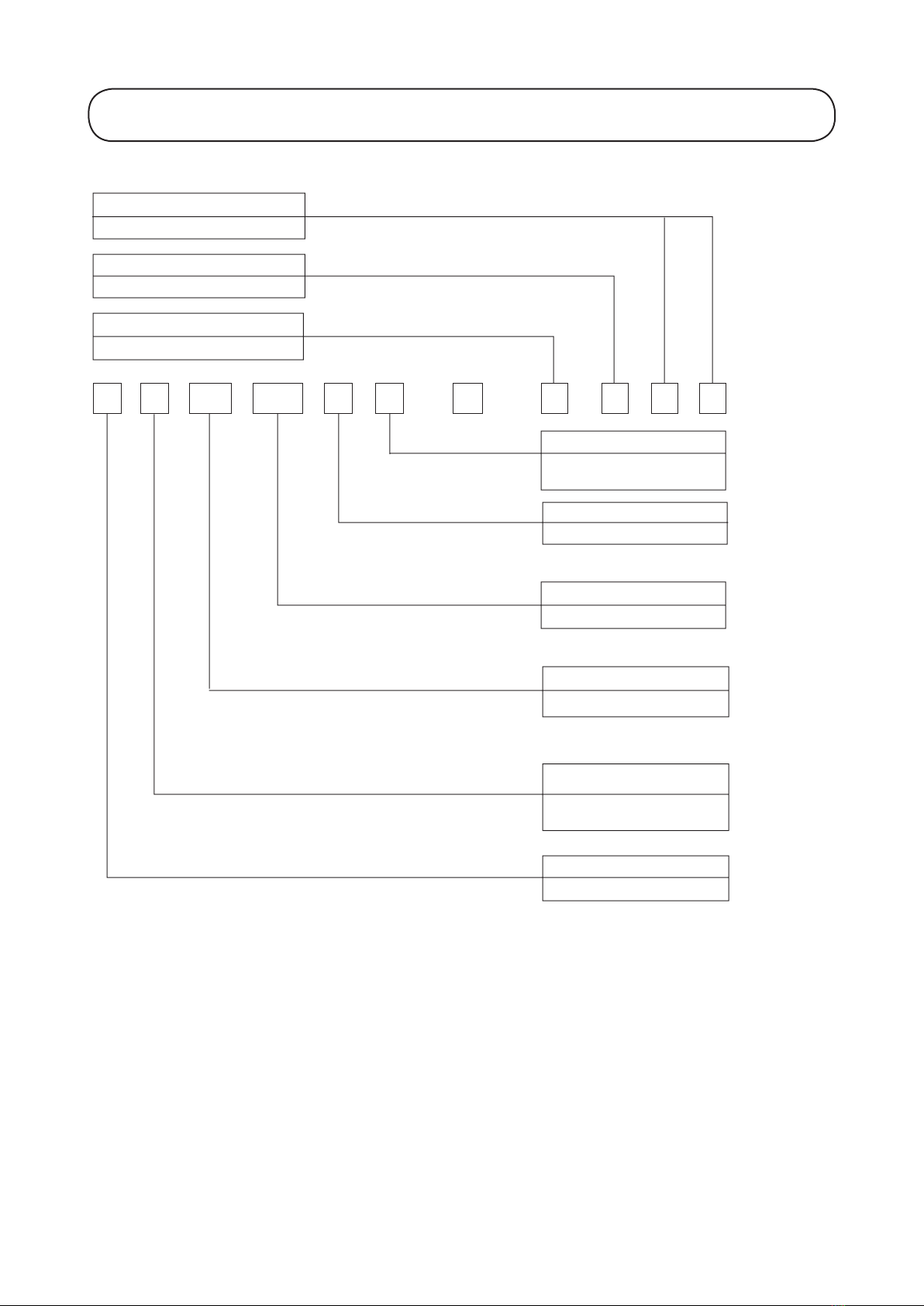
1. NOMENCLATURE

2
A 4 MC 75 E R - F B A A
Series
E: E Series
D: D series
Model Type
R: Heatpump
Omitted if cooling only
Capacity
75: 75,000 Btu/h
Model Name
MC: Single Split
Condensing Unit
Refrigerant
Blank: R22
4: R407C
Brand
A: ACSON
Electrical Characteristic
F: 50Hz / 3Ph / 380-415V
P: 60Hz / 3Ph / 208-230V
Q: 60Hz / 3Ph / 460V
Type of connection
B: For Brazed
A: First Issue
3
Indoor Unit ACC-D Series
Control
Handset
Marking
NETWARE 3
L2
CE Mark
Cap. Tube
TXV
75D ABAA XXX X XXX
100D ABAA XXX X XXX
75DR ABAA XXX X XXX
100DR ABAA XXX X XXX
Cooling
Model
Heat Pump
Model
With Air Filter
X
X
Fin
ALUMINIUM
(CORR.)
X
X
Level Switch
Classification
Refrigerant
Control
ACC
NONMENCLATURE
Built-in Filter Rail
Product Line-up

4
Compressor
With Contactor
Without Contactor
With 24Vac Control Circuit
With Auto HP/LP
With Manual HP/LP
CE Mark
ETL
Without Marking
Scroll-Copeland
TXV
Without Expansion Device
Rivet "Made In Malaysia"
With Accumulator
With Type Brazed Ball Valve
Phase Protector
Gold Fin (NA549)
FBAF X X X X X X
FBAG X X X X X X
FBAH X X X X X X
FCAA X X X X X X
FCAB X X X X X X X
PBAB X X X X X
PBAC X X X X X X X
PCAA X X X X X X
QBAB X X X X X
QBAC X X X X X X X
QCAB X X X X X X X X
FBAF X X X X X X
FBAG X X X X X X
FBAH X X X X X X
FCAA X X X X X X
FCAB X X X X X X X
PBAB X X X X X
PBAC X X X X X X X
PCAA X X X X X X
QBAB X X X X X
QBAC X X X X X X X
QCAB X X X X X X X X
A4MC-D Series Product Line Up
Marking
Compressor
With Contactor
Auto HP/LP
CE Mark
Scroll-Copeland
TXV
Without Expansion Device
For Sequential Controller
With Accumulator
With Type Brazed Ball Valve
Gold Fin (NA549)
FBAA XXXX XX
FBAA XXXX XXX
FCAA XXXX XX X
FCAB XXXX XXXXX
FBAA XXXX XX
FBAA XXXX XXX
FCAA XXXX XX X
FCAB XXXX XXXXX
1-1/8
Others
Liquid Pipe Size (in)
Gas pipe size (in)
1
Cooling Only Model
75D 1/2 1
100D 5/8 1-1/8
Cooling Only Model
75D 1/2
A4MC
Nomenclature
Controller
Refrigerant
Control
100D 5/8
Classification
Classification
AMC
Nomenclature
Controller Marking
Refrigerant
Control
Others
Liquid Pipe Size (in)
Gas Pipe Size (in)
Outdoor Unit
AMC-D Series Product Line Up

5
Outdoor Unit
AMC-ER Series Product Line Up
Marking
Compressor
With Contactor
With Auto HP/LP
CE Mark
Scroll-Copeland
TXV
Without Expansion Device
For Sequential Controller
Gold Fin (NA549)
Rivet "Made In Malaysia"
With Brazed Type Ball Valve
Check valve
Phase Sequencer
FBAA XXXXX X
FBAB XXXXX XX
FBAC X X X X X X X
FCAA XXXXX X X
FBAA XXXXX X
FBAB XXXXX XX
FBAC X X X X X X X
FCAA XXXXX X X
FBAA XXXXX X
FBAB XXXXX XX
FBAC X X X X X X X X
FCAA XXXXX X X
FBAA XXXXX X
FBAB X X X X X X X X
FCAA XXXXX X X
A4MC-ER Series Product Line Up
Marking
Compressor
With Contactor
With Auto HP/LP
CE Mark
Scroll-Copeland
TXV
Without Expansion Device
For Sequential Controller
Gold Fin (NA549)
With Accumulator
With Brazed Type Ball Valve
FBAA XXXXX X
FCAA XXXXX X X
FBAA XXXXX X
FCAA XXXXX X X
FBAA XXXXX X
FCAA XXXXX X X
FBAA XXXXX X
FCAA XXXXX X X
125ER 5/8 1-3/8
150ER 5/8 1-3/8
Others
Liquid Pipe Size (in)
Gas Pipe Size (in)
Heatpump Models
75ER 1/2 1
100ER 5/8 1-1/8
A4MC
Nomenclature
Controller
Refrigerant
Control
150ER 5/8 1-3/8
Classification
HEATPUMP MODLES
75ER 1/2 1
100ER 5/8 1-1/8
125ER 5/8 1-3/8
Classification
AMC
Nomenclature
Controller
Refrigerant
Control
Others
Liquid Pipe Size (in)
Gas Pipe Size (in)

6
Invisible Operation
The unit is installed concealed above the ceiling. ACC-D is designed to intelligently create a comfortable and
healthy indoor air climate, while remaining invisible. This allows user to enjoy conditioned air without sacricing
room space or interior design creativity.
Flexibility In System Design
The unit offers fan motor that can operate up to 4 speeds, thus provide choices of external static pressure for
designing ducting system.
Easy Serviceability
With the concept of easy serviceability in mind, ACC-D series is designed for easy access to internal components.
The internal components, such as fan motor or blower, can be easily accessed for servicing through both sides
or bottom of the unit.
High Level Of Protection
The unit is incorporated with a unique safety feature, i.e. a oat switch, to provide an additional protection from
possible problems of condensate water over ow inside the unit. Once the condensate water reaches critical level,
the level switch will be activated and signal will be sent to the microprocessor controller to stop the compressor
as well as sending an error message to the wired controller, alerting the user, for further action.
Wired Remote Controller
The standard unit comes with the Netware III controller, which offers wide range of control features that, includes
7 days and 24 hours timer setting and more. The ACC-D series is able to communicate with the versatile NIM
network control module and offers the opportunity of one centralized control for a system of multiple indoor
units in a building.
Auto Random Restart
Auto random restart function allows the unit to automatic restart as the last setting condition when the power
supply is resumed after power failure. However, the compressor will restart randomly if more than one unit is
installed and sharing the same phase of power.
Self Diagnosis
The microprocessor provides the possibility to detect and diagnose any fault or malfunction that occurs in the
system. The error will be reected by the wired remote controller with a series of error code.
2. FEATURES

7
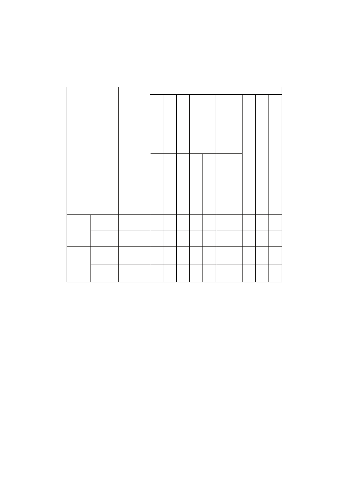
Operating Range
Ensure the operating temperature is in allowable range.
Cooling only
Heat pump
Outdoor temp. (°CDB)
Indoor temp. (°CWB)
Heating
Outdoor temp. (°CWB)
Indoor temp. (°CDB)
Cooling
Outdoor temp. (°CDB)
Indoor temp. (°CWB)
-9
15 21
6
27
-5
19
35
15
46
24
54
Standard
point
High ambient unit
Low ambient kit
18
-5
19
35
15
46
24
54 High ambient
unit
Low ambient kit
Standard
point
Standard
point
Caution :
The use of your air conditioner
outside the range of working
temperature and humidity can result
in serious failure.
Note :
Standard operating range.
With High ambient unit. (Optional item)
Please refer to local dealer for unit of this specification.
With Low ambient kit. (Optional item)
Please refer to local dealer for unit of this specification.
3. APPLICATION INFORMATION

8
Refrigerant Circuit Diagrams
Model: ACC 75D – AMC 75D ACC 100D – AMC 100D
ACC 75D – A4MC 75D ACC 100D – A4MC 100D
Model: ACC 75DR – AMC 75ER ACC 100DR – AMC 100ER
ACC 75DR – A4MC 75ER ACC 100DR – A4MC 100ER
9
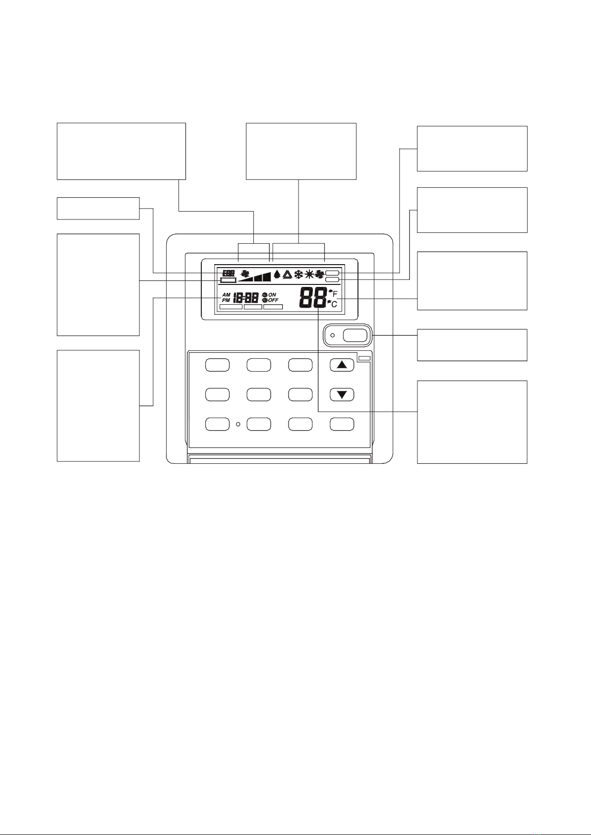
Controllers
°C or °F Display
Display the
temperature in °C
or °F.
HEAT
TEMP.
Key Lock
Display
Display
indicates when
key lock
function is
activated.
FAN
SET TIMER
ON TIMER
DAY
Current Time,
Start / Stop
Time Display
Display the
current time as
well as the start
and stop time
programmed.
CLOCK
HOLD
SWING
SLEEP
TIMER ACTIVE
Set Temperature
or Room
Temperature
Display
Display the set or
room temperature.
MINUTE
HOUR
OFF TIMER
SET TEMP
MODE
ROOM
TEMP.
SET C LOCK
ON / OFF
On/Off Status Lamp
Display
Operation Mode
Display
Displays the current
mode of operation.
AUTO
MON TUE WED THU FRI SAT SUN
Error Display
KEY LOCK
Fan Speed Display
Displays the fan speed
setting.
(Auto/High/Medium/Low)
SLEEP
SWING
COOL
TEMP.
COOLAUTODRY FANHEAT
Swing Display
Display the air swing
status.
Sleep Display
Display the sleep /
energy saving status.
Netware III

10
DAYHOLD
CLOCK
HOUR
ON TIMERSWING
SLEEP
OFF TIMER
MODE
MINUTE
SET TEMP
ON / OFF
FAN
MON TUE WED THU FRI SAT SUN
SET TIMER
AUTO
TIMER ACTIVE
KEY LOCK
ROOM
TEMP.
HEAT
TEMP.
COOL
TEMP.
AUTO
SET CLOCK
DRY HEATCOOL SWING
SLEEP
On / Off
Starting operation:
When the unit is off, press
the ON/OFF button. The
operation LED lights and
the unit will be turned on.
Stopping operation:
When the unit is on, press
the ON/OFF button. The
operation LED is
extinguished and controls
are turned off.
Set Temperature
Press this button to set
the temperature. By
pressing up or down once,
temperature changes by
1°C (or 1°F).
The temperature range is
16°C to 30°F (60°F to
85°F).
In FAN mode,
temperature cannot be
set.
Pressing up and down
buttons simultaneously
will toggle the temperature
unit between °C and °F.
When set temperature
button is pressed, the set
temperature will be
displayed for 5 seconds.
After that, room
temperature will be
displayed.
Operating Lamp
Mode
Press MODE button to
select operation mode from
Cool, Heat, Auto, Dry and
Fan. The display will show
the selected mode.
Swing
Press SWING button to
activate the air sweep
function.
Sleep
Press SLEEP button to
activate the sleep or
energy saving mode.
Fan
Press FAN button to
select Auto, High,
Medium or Low fan
speed.
FAN

11
DAY
CLOCK
HOUR
ON TIMERSWING
SLEEP
OFF TIMER
MODE
MINUTE
SET TEMP
ON / OFF
FAN
MON TUE WED THU FRI SAT SUN
SET TIMER
AUTO
TIMER ACTIVE
KEY LOCK
ROOM
TEMP.
HEAT
TEMP.
COOL
TEMP.
AUTO
SET CLOCK
DRY HEATCOOL SWING
SLEEP
Key Lock
Operating Lamp
FAN
Current Time DisplayTimer Active Display
– This feature protects the
controls from being
tempered with by children or
unauthorized persons.
– To activate, press MINUTE
button three times consecu-
tively, “KEY LOCK” symbol
will appear on the LCD
display.
– During this time, ON/OFF
button and FAN button can
be used.
– To cancel this feature, press
the MINUTE button again
three times consecutively.
When the control is in set clock
or set timer mode, pressing the
MINUTE button will change the
set minute.
Minute
When the control is in set clock
or set timer mode, pressing the
HOUR button will change the
set hour.
Hour
When the control is in set clock
or set timer mode, pressing the
DAY button will change the set
hour.
– Press button once to set the clock mode.
– Press button again to disable the clock mode.
– When the clock mode is activated, the time and date can be
set or changed by pressing ther DAY, HOUR & MINUTE button.
Day
Clock
– Press button until “TIMER ACTIVE” appears to activate the timer.
– The symbol will indicate Event 1, Event 2 and/or Event 3 timers
are active.
– To clear the timer setting, press and hold TIMER ACTIVE button
for 2 to 3 second until the word “TIMER ACTIVE” is no longer
display.
–To resume the timer setting after the timer has been deactivated,
press and hold TIMER ACTIVE button again for 2 to 3 seconds
until the word “TIMER ACTIVE” is displayed.
Timer Active
TIMER ACTIVE

12
Operating State and Fault Table
Wired Handset – Netware III
Cooling / Heat Pump Model
Phase Sequencer
The unit with Scroll Compressor can only rotate in one direction. For this reason, a protective device (phase
sequencer) is fitted to prevent incorrect wiring of the electrical phases. When the three phases are not
connected correctly, the phase sequencer operates, and the unit will not start. This devise is located in the
control box of the outdoor unit.
The following table shows the LED indicator light for phase sequencer under normal operation and fault
conditions.
Room sensor open or short
Indoor coil sensor open
Outdoor coil sensor open
Compressor overload / Indoor or
outdoor coil sensor short
Error Code
Event
Blink E1
Blink E2
Blink E3
Blink E4
Notes: 1. “-“ means LED off.
2. When R phase missing, no LED or buzzer will indicate the error, but relay 71
(Common) and 81 (NO) will cut off.
3. The unit will check the discharge sensor availability only during power up.
4. All errors can only recover through manually reset.
Normal Operation On - - -
Reverse Phase Blink Blink Blink Blink
S & T Phase Missing Blink - Blink Blink
T Phase Missing Blink - - Blink
S Phase Missing Blink - Blink -
R Phase Missing - - - -
Overload Blink - - -
Sensor Missing Blink On On On
LED-P
(Red)
LED-R
(Yellow)
LED-S
(Yellow)
LED-T
(Yellow)

13
Installation
Caution
Sharp edges and coil surfaces are potential injury hazard. Avoid from contact with them.
(1) Installation of Indoor Unit
Preliminary Site Survey
• Electrical supply and installation is to confirm to local authority’s (e.g. National Electrical Board) codes and
regulations.
• Voltage supply fluctuation must not exceed ± 10% of rated voltage. Electricity supply lines must be inde-
pendent of welding transformers which can cause high supply fluctuation.
• Ensure that the location is convenient for wiring, piping and drainage.
Standard Mounting
Ensure that the overhead supports are strong enough to hold the weight of the unit. Position the hanger
rods and check for its alignment with the unit. Also, check that the hangers are secured and the base of the
fan coil unit is leveled in both horizontal directions, taking into account the gradient for drainage flow as
recommended in Figure A.
10.0
The indoor unit must be installed such that there is no short circuit of the cool discharge. Comply with the
installation clearance recommended as shown in Figure B. Do not put the indoor unit where there is direct
sunlight on the unit. Make sure the location is suitable for piping and drainage.
Figure B
Figure A
800.0 800.0
800.0

14
Pipings
Do not use contaminated or damaged copper tubings. If pipings, evaporator or condenser is exposed or had
been opened for 15 seconds or more, vacuum and purge with eld supplied refrigerant. Generally, do not
remove plastic, rubber plugs or caps from ttings, tubings and coils until ready to connect suction or liquid
line into ttings.
For ACC 75/100D/DR, the piping connections are brazing type. If any brazing work is required, ensure that
nitrogen gas is passed through coil and joints while brazing work is being done. This will eliminate soot
formation on the inside walls of copper tubings.
Electrical Connection
As wiring regulations differ from each country, please refer to your LOCAL ELECTRICAL CODES for eld
wiring regulations and ensure that they are complied with. Besides, take note of the following general
precautions:
1. Ensure that the rated voltage of the unit correspond to the name plate before commencing wiring work.
2. Provide a power outlet to be used exclusively for each unit and a power supply disconnect and a circuit
breaker for over-current protection should be provided in the exclusive line.
3. The unit must be EARTHED to prevent possible hazards due to insulation failure.
4. All wiring must be rmly connected.
5. Electrical wiring must not touch the refrigerant piping, compressor and any moving parts of the fan motor.
Operational Check
After all wiring is completed and system is charged with refrigerant, make sure unit is operating properly.
Check that:
1. Condenser fans are running with warm air blowing off the condenser coil.
2. Evaporator fans are running and discharging cool air.
3. Suction line pressures and condensing pressures are in the range of 60 – 75 psig. and 260 – 300 psig.
respectively in cooling cycle or 45 – 60 psig. and 245 – 285 psig. respectively in heating cycle.
4. Microprocessor electronic thermostats as used in the remote controls incorporate a 3 minutes delay in
their circuit. Thus it requires about 3 minutes upon start-up before the outdoor unit is activated.

15
(2) Installation of Outdoor Unit
AMC Series
As condensing temperature rises, evaporating temperature rises and cooling capacity drops. In order to achieve
maximum cooling capacity, the location selected for outdoor unit should fulll the following requirements:
• Install the condensing (outdoor) unit in a way such that hot air distributed by the outdoor condensing unit
cannot be drawn in again (as in the case of short circuit of hot discharge air). Allow sufcient space for main-
tenance around the unit
• Ensure that there is no obstruction of air ow into or out of the unit. Remove obstacles which block air intake
or discharge.
• The location must be well ventilated, so that the unit can draw and distribute plenty of air thus lowering the
condensing temperature.
• A place capable of bearing the weight of the outdoor unit and isolating noise and vibration.
• A place protected from direct sunlight. Otherwise use an awning for protection, if necessary.
• A place where the hot air discharge and operating sound level will not annoy the neighbours.
• The location must not be susceptible to dust or oil mist.
Installation Clearance
• Outdoor units must be installed such that there is no short circuit of the hot discharge air or obstruction to
smooth air ow.
CAUTION : If the condensing unit is operated in an atmosphere containing oils (including machine
oils), salt (coastal area), sulphide gas (near hot spring, oil renery plant), such substances may lead
to failure of the unit.
2000mm
1000mm
300mm
300mm
300mm
16
(3) Refrigerant Piping
Field Piping
To ensure satisfactory operation and performance, the following points should be noted for the eld piping
arrangements of the complete refrigerant cycle.
a) Liquid loops or oil traps must be provided according to the position of the outdoor and indoor units (depend-
ing on whether the indoor unit is above or below the outdoor unit).
b) Field supplied lter dryer should be provided as close to the expansion valve(s) of the indoor unit
(evaporator) as possible.
c) Field supplied sight glass must be assembled and mounted next to lter dryer.
Maximum Piping Length and Maximum Number of Bends
When the pipe length becomes too long, both the capacity and reliability drop. As the number of bends
increases, system piping resistance to the refrigerant ow increases, thus lowering the cooling capacity,
and as the result the compressor may become defective. Always choose the shortest path and follow the
recommendation as tabulated below:
Model
Indoor
Outdoor
ACC 75/100 D/DR
AMC/A4MC
75/100 D/DE
Maximum Length, m 35
Maximum Elevation, m 20
Maximum No. of Bends 8
CAUTION:
1) Our guarantee on the performance of our air-conditioners is strictly revoked if the height, length
and/or the number of bends of the refrigerant piping system installed is beyond the limit above.
2) Bendings must be carefully made so as not to crush the pipe. Use a pipe bender to bend a pipe as
far possible.
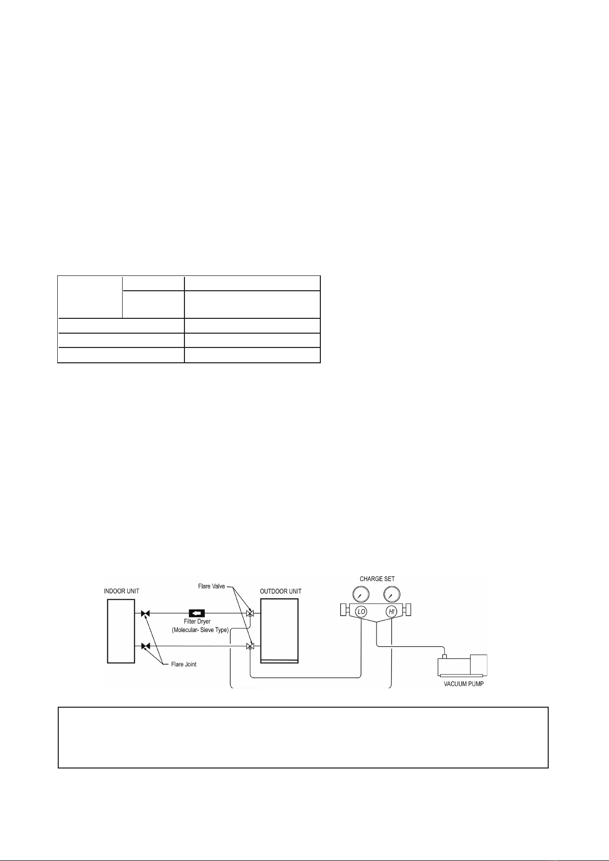
(4) Vacuuming and Charging
The pre-charged outdoor unit does not need any vacuuming or charging. However once it is connected, the
connecting pipe line and the indoor unit need to be vacuumed before releasing the R22/R407C from the out-
door unit.
1. Open the service port core cap.
2. Connect pressure gauge to the service port.
3. Connect the line to vacuum pump. Open the charging manifold valve and turn the pump on. Vacuum to -0.1
MPa (-760mmHg) or lower. (Evacuation time varies by the pump but averagely in 1 hour).
CAUTION FOR R407C
Do not top-up when servicing leak, as this will reduce the unit performance. Vacuum the unit
thoroughly and then charge the unit with fresh R407C according to the amount recommended
in the specication.
17
Guidelines Of Field-charging Air Conditioning Systems With Scroll Compressors
These guidelines are intended for use with Scroll compressors only with R22, R407C, R134a, R404A, R507,
and R410A refrigerants. They do not apply to reciprocating compressors or competitive Scroll compressors.
Field-charging - Some Precaution Points
Scroll compressors have a very high volumetric efciency and quickly pump a deep vacuum if there is
insufcient refrigerant in the system or if refrigerant is added too slowly. Operation with low suction pressure
will quickly lead to very high discharge temperatures. While this process is happening, the scrolls are not being
well lubricated - scrolls depend on the oil mist in the refrigerant for lubrication. A lack of lubrication leads to high
friction between the scroll anks and tips and generates additional heat. The combination of heat of compres-
sion and heat from increased friction is concentrated in a small localized discharge area where temperatures
can quickly rise to more than 300°C. These extreme temperatures damage the Scroll spirals and the orbiting
Scroll bearing. This damage can occur in less than one minute especially on larger compressors. Failure may
occur in the rst few hours or the damage done during eld charging may show up some time later.
Other typical eld charging problems include undercharging, overcharging, moisture or air in the system etc.
In time each one of these problems can cause compressor failure.
Equipment
Minimal equipment is required for eld charging. The minimum equipment required to do a satisfactory job is:-
Set of service gauges
Hoses
Vacuum pump
Vacuum gauge
Scales
Thermometer
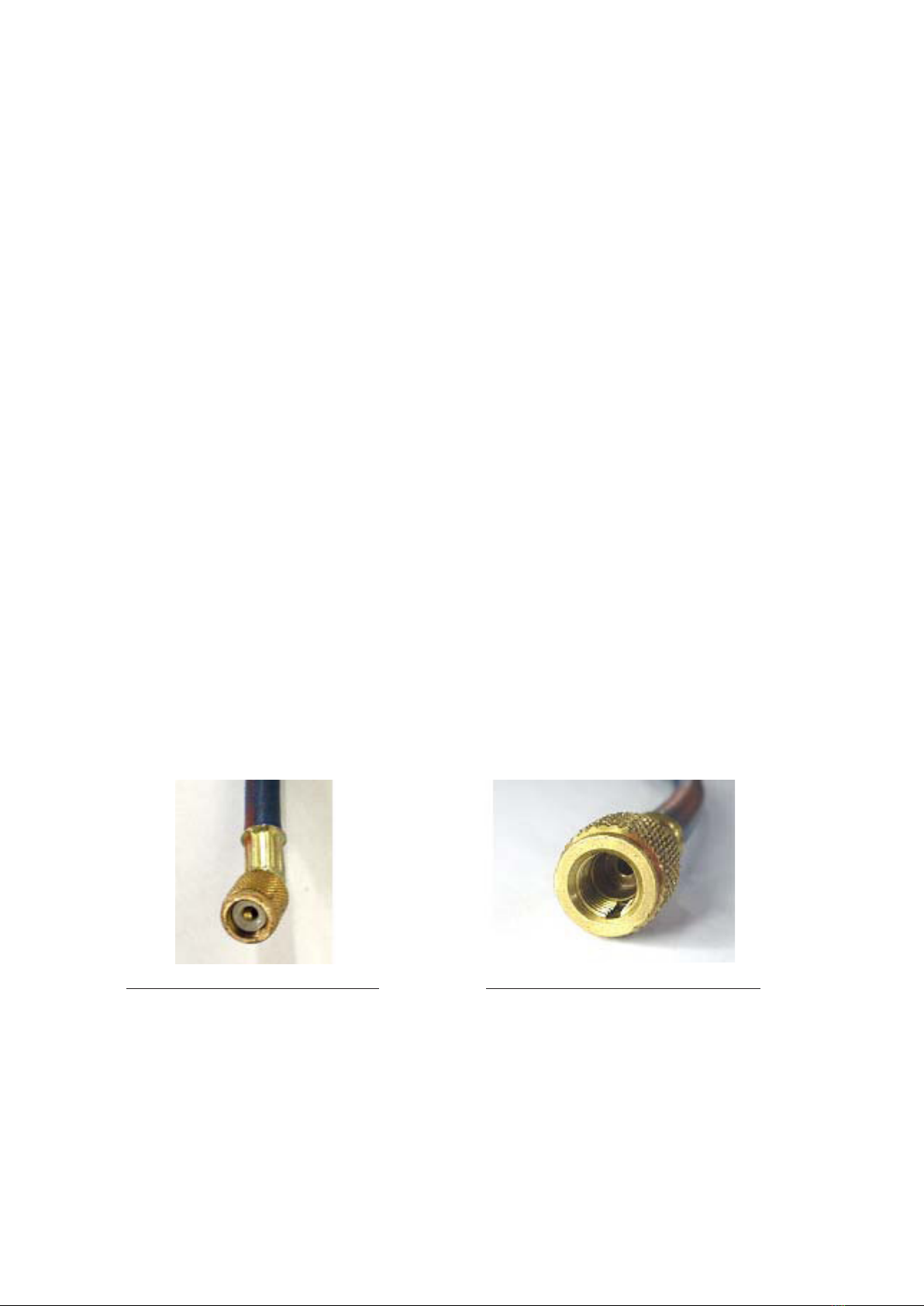
Charging Hoses
Most eld-charging is done using standard service hoses. Hoses are made in different colors with
different working pressures and with different leak rates but the most important point is the presence or
absence of Shredder valve depressors. Shredder valve depressors severely restrict the ow through the
service hoses. This slows evacuation and vapor charging dramatically. In most cases the Shredder depressor
can be removed but it is simpler to have one set of hoses with and one set without Shredder depressors.
Hose with Shredder valve Depressor Hose without Shredder valve Depressor
Hose selection is important depending whether the system is being evacuated or charged. Charging liquid
from the cylinder into the liquid line should be carried out using an open hose connected to an unrestricted
tting. This will reduce charging time.
18
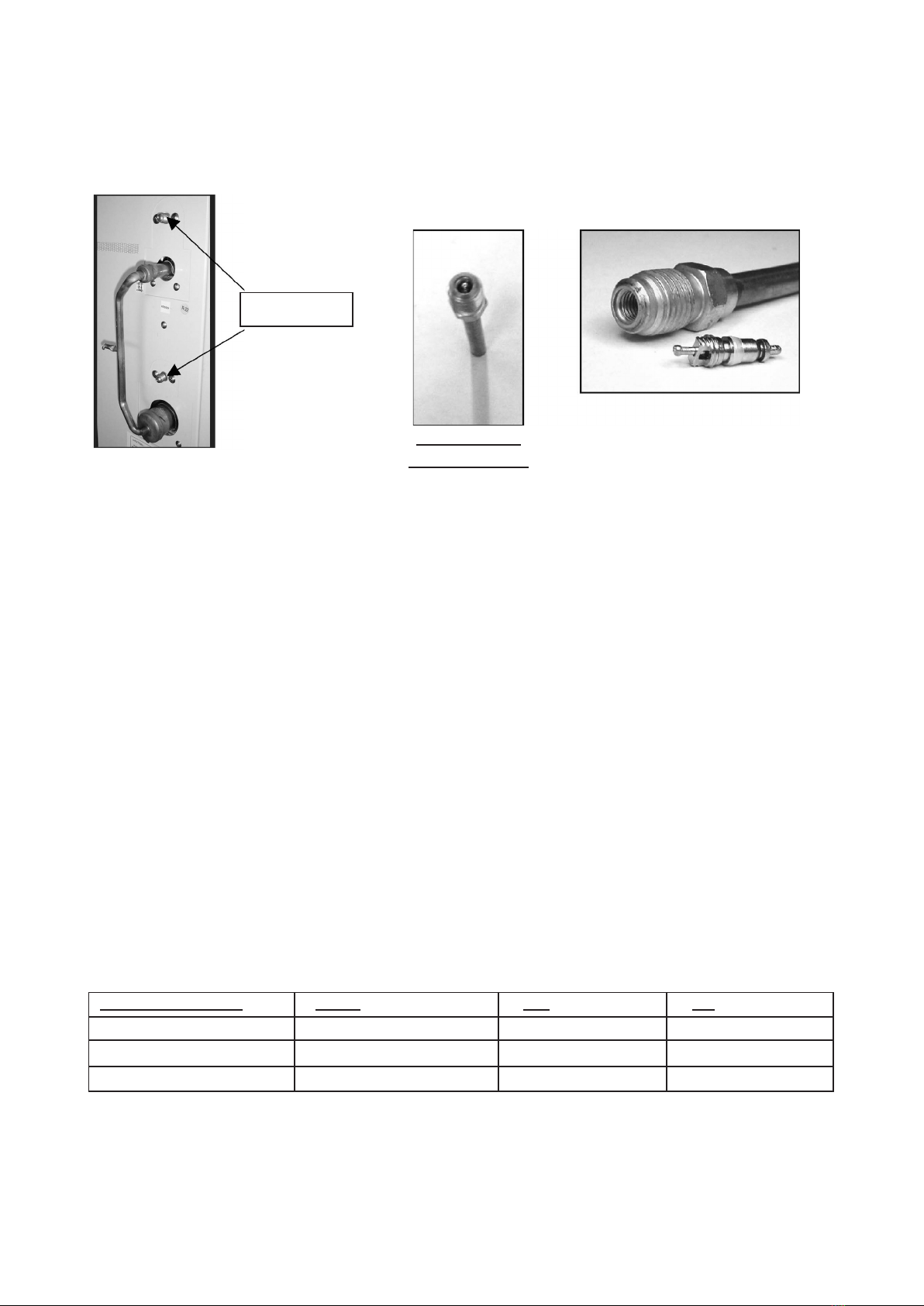
Typical service valves
Found on the outdoor unit
Most split systems have a suitable connection on the outdoor unit
Shredder valves provide easy system access for pressure reading and addition of refrigerant. On small sys-
tems, they provide a reasonable connection for evacuation also. However, Shredder valves and the hoses
connected to them can cause very severe pressure drops and can multiply evacuation time by a factor of 4
or 5.
On the positive side, Shredder valves provide a restriction that slows the speed of liquid charging into the
suction side. When a pressure drop is desirable (charging liquid into suction), connect via a Shredder valve.
When a pressure drop is detrimental (evacuation), connect via an open tting.
How Much Refrigerant?
The proper refrigerant charge should follow the volume as recommended by manufacturer and
recommendation should be followed by the installer. Refer to the table of Refrigerant Charge Level.
If the installer cannot nd the correct charge but the system must be started, refrigerant should be
carefully added to the system until reasonable sub-cooling is measured in the liquid line and reasonable
suction superheat is measured at the compressor suction. Suction and discharge pressures must be moni-
tored carefully during the charging process.
Charge Limits
Copeland Scroll compressors have the different charge limits for different compressor models as shown in
table below. If the total charge exceeds these limits, the system should have a crankcase heater and/or pump
down cycle and/or accumulator to prevent liquid damage to the compressor. Some systems may require ac-
cumulators to limit liquid oodback even though the charge is lower than the published limit.
Shredder core
Shredder valves
Shredder valve
with core in place
Shredder valve with core removed
Compressor Range Model Ibs. kg.
Quest ZR46 to ZR81 10 4.5
Summit ZR84 to ZR144 16 7.3
Specter ZR90 to ZR19M 17 7.7
This manual suits for next models
14
Table of contents
Other Acson Inverter manuals


