Actel ProASIC PLUS User manual

ProASICPLUS Evaluation Board
User’s Guide
QS_Tutorial_eval.book Page i Monday, January 13, 2003 1:08 PM

ii
Actel Corporation, Sunnyvale, CA 94086
© 2002 Actel Corporation. All rights reserved.
Printed in the United States of America
Part Number: 51700003-0
Release: December 2002
No part of this document may be copied or reproduced in any form or by any means
without prior written consent of Actel.
Actel makes no warranties with respect to this documentation and disclaims any im-
plied warranties of merchantability or fitness for a particular purpose. Information
in this document is subject to change without notice. Actel assumes no responsibil-
ity for any errors that may appear in this document.
This document contains confidential proprietary information that is not to be dis-
closed to any unauthorized person without prior written consent of Actel Corpora-
tion.
Trademarks
Actel and the Actel logotype are registered trademarks of Actel Corporation.
Adobe and Acrobat Reader are registered trademarks of Adobe Systems, Inc.
Liberty is a licensed trademark of Synopsys Inc. This product uses SDC, a Propri-
etary format of Synopsys Inc.
Libero is a trademark of Actel Corporation.
Mentor Graphics, Viewlogic, ViewDraw, MOTIVE, and ModelSim are registered
trademarks of Mentor Graphics, Inc.
Synplify and Synplicity are registered trademarks of Synplicity, Inc.
Verilog is a registered trademark of Open Verilog International.
WaveFormer Lite and SynaptiCAD are trademarks of SynaptiCAD, Inc.
Windows is a registered trademark and Windows NT is a trademark of Microsoft
Corporation in the U.S. and other countries.
All other products or brand names mentioned are trademarks or registered trade-
marks of their respective holders.
QS_Tutorial_eval.book Page ii Monday, January 13, 2003 1:08 PM

iii
Table of Contents
Introduction . . . . . . . . . . . . . . . . . . . . . . . . . . . . . . .5
Document Contents . . . . . . . . . . . . . . . . . . . . . . . . . . . .5
Document Assumptions . . . . . . . . . . . . . . . . . . . . . . . . . . 5
1Contents and System Requirements . . . . . . . . . . . . . . . .7
Evaluation Kit Contents . . . . . . . . . . . . . . . . . . . . . . . . . .7
System Requirements . . . . . . . . . . . . . . . . . . . . . . . . . . . .8
2Setup and Self Test . . . . . . . . . . . . . . . . . . . . . . . . . . .9
Software Installation . . . . . . . . . . . . . . . . . . . . . . . . . . . .9
Testing the Evaluation Board. . . . . . . . . . . . . . . . . . . . . . . .9
Programming the Test file . . . . . . . . . . . . . . . . . . . . . . . . 10
3Hardware Description . . . . . . . . . . . . . . . . . . . . . . . . 11
Power Supplies . . . . . . . . . . . . . . . . . . . . . . . . . . . . . . 12
Programming Headers . . . . . . . . . . . . . . . . . . . . . . . . . . 12
Clock Circuits . . . . . . . . . . . . . . . . . . . . . . . . . . . . . . . 13
LED . . . . . . . . . . . . . . . . . . . . . . . . . . . . . . . . . . . . 13
Switches . . . . . . . . . . . . . . . . . . . . . . . . . . . . . . . . . . 14
ABoard Connections . . . . . . . . . . . . . . . . . . . . . . . . . 17
BBoard Schematics . . . . . . . . . . . . . . . . . . . . . . . . . . . 29
CProduct Support . . . . . . . . . . . . . . . . . . . . . . . . . . . 35
Actel U.S. Toll-Free Line . . . . . . . . . . . . . . . . . . . . . . . . . 35
Customer Service . . . . . . . . . . . . . . . . . . . . . . . . . . . . . 35
Customer Applications Center . . . . . . . . . . . . . . . . . . . . . . 36
Guru Automated Technical Support . . . . . . . . . . . . . . . . . . . 36
Web Site. . . . . . . . . . . . . . . . . . . . . . . . . . . . . . . . . . 36
FTP Site . . . . . . . . . . . . . . . . . . . . . . . . . . . . . . . . . . 36
Contacting the Customer Applications Center . . . . . . . . . . . . . . 36
Worldwide Sales Offices . . . . . . . . . . . . . . . . . . . . . . . . . 38
QS_Tutorial_eval.book Page iii Monday, January 13, 2003 1:08 PM

QS_Tutorial_eval.book Page iv Monday, January 13, 2003 1:08 PM

5
Introduction
Thank you for purchasing Actel’s ProASICPLUS Evaluation Board.
The purpose of this user’s guide is to provide you with information so you can
easily evaluate the ProASICPLUS devices.
This is the first release of the user’s guide. The most up-to-date version of this
guide is available at:
http://www.actel.com/products/tools/hw.html
Document Contents
Chapter 1 - Contents and System Requirements describes the
contents of the ProASICPLUS Evaluation Kit.
Chapter 2 - Setup and Self Test describes how to setup the ProASICPLUS
Evaluation Board and how to perform a self test.
Chapter 3 - Hardware Description describes the components of the
ProASICPLUS Evaluation Board.
Appendix A - Board Connections lists a board connection table.
Appendix B - Board Schematics show illustrations of the ProASICPLUS
Evaluation Board.
Appendix C - Product Support describes our support services.
Document Assumptions
This user’s guide assumes the following:
• You intend to use Actel’s Libero software.
• You have installed and are familiar with Actel’s Libero software.
• You are familiar with the VHDL or Verilog hardware description language.
• You are familiar with UNIX workstations and operating systems or PCs and
Windows operating systems.
QS_Tutorial_eval.book Page 5 Monday, January 13, 2003 1:08 PM

QS_Tutorial_eval.book Page 6 Monday, January 13, 2003 1:08 PM

7
1
Contents and System Requirements
This chapter describes the differences between the three versions of the
ProASICPLUS evaluation board. This chapter also details the contents of the
ProASICPLUS evaluation kit and provides power supply and software system
requirements.
Evaluation Kit Contents
The ProASICPLUS evaluation kit has three board versions.
Note: There is no socket on these boards.
APA-EVAL-BRD1
This board contains all the surrounding circuitry, but no APA device. For this
board, it is assumed that you will acquire a device and solder it to the board
yourself. This allows you to use the board with any device in the APA family.
APA-EVAL-BRD300
Same as BRD1 but with an APA300 device mounted.
APA-EVAL-BRD075
Same as BRD1 but with an APA075 device mounted.
When you purchase any of the above board versions, you also receive the
following:
• Evaluation board - one of the three listed above
• The ProASICPLUS Evaluation Board User’s Guide
•CustomerLetter
• CD with design examples
For the CD contents, review the ReadMe.doc file at the top level of the
CD. As more design examples become available, the CD contents will
change. For the latest design examples, refer to the Hardware Tools
section of the Actel website:
http://www.actel.com/products/tools/hw.html
QS_Tutorial_eval.book Page 7 Monday, January 13, 2003 1:08 PM

Chapter 1: Contents and System Requirements
8
Power Supply and Software Requirements
This section describes power supply and software requirements for the
ProASICPLUS evaluation kit.
Power Supply The ProASICPLUS evaluation board requires the following:
• Wall mount power supply
• 9V, 500mA supply with 2.1mm female connector P5 type
• Digikey part number T413-P5P-ND for US
• Digikey part number T408-P5P-ND for Europe
Software Each ProASICPLUS evaluation board requires a different version of the
software.
APA-EVAL-BRD075
This board can use the free evaluation Libero Silver version, which
does not include simulation. To include simulation, use the Libero Gold
version.
APA-EVAL-BRD300
This board requires a full Libero Platinum license.
APA-EVAL-BRD1
With the blank board, you can select any device from the ProASICPLUS family
in a 208 PQFP footprint and solder it to the board yourself.
Use the appropriate software for the device you choose. For software support
details, refer to the Actel Website:
http://www.actel.com/products/tools/support.html
QS_Tutorial_eval.book Page 8 Monday, January 13, 2003 1:08 PM

9
2
Setup and Self Test
Software Installation
Since this package does not include software, this guide does not provide
software installation instructions. For software installation instructions, refer to
the Actel Installation and Licensing Guide at:
http://www.actel.com/products/tools/libero/docs.html
Testing the Evaluation Board
If the evaluation board is shipped directly from Actel, it contains a test program
that determines if the board works properly.
To test the evaluation board:
1. Supply power to the board.
2. Turn on the ON/OFF switch.
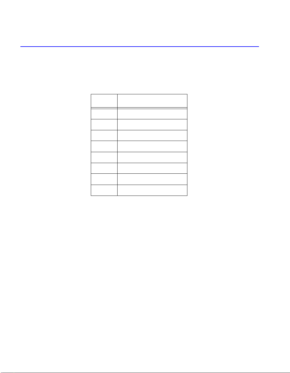
3. Perform the actions described in Table 2-1.
Table 2-1. Evaluation Board Test
Action Result Pass/Fail
Press PB1 multiple times, but not
too fast A sequence of LEDs light up Pass
Press and hold SW1 All LEDs are unlit Pass
Press and hold SW2 All LEDs light up except DS1 Pass
Press and hold SW3
A random sequence of LEDs
light up while you hold the
switch
Pass
Press and hold SW4 The LED is lit/unlit in a
01101010 pattern Pass
Any two switches are pressed
together Creates a 00100110 pattern. Pass
QS_Tutorial_eval.book Page 9 Monday, January 13, 2003 1:08 PM

Chapter 2: Setup and Self Test
10
Programming the Test file
If you want to retest the evaluation board, you can reprogram the board using
the test program at any time. Use the STAPL file test.stp or the bitstream file
test.bit. These files are included on the Evaluation Kit CD. Table 2-2 describes
the actions you should perform when retesting your evaluation board.
This design is currently implemented for the APA300 device. If you have a
device of a different size, you can recompile the design into other device sizes.
The design files are available under actelprj/eval in the Evaluation Kit CD.
For instructions on programming the device using Flash Pro, refer to the Flash
Pro User’s Guide at:
http://www.actel.com/techdocs/manuals/docs/flashproUG.pdf
Table 2-2. Retesting the Evaluation Board
Action Result Pass/Fail
Press PB1 multiple
times, but not too fast
Count sequence should be visible on
the LED Pass
Press and hold SW1 All LEDs are unlit Pass
Press and hold SW2 All LEDs are lit Pass
Press and hold SW3 Count sequence runs while you hold
the switch Pass
Press and hold SW4 LED is lit/unlit alternately in a
10101010 pattern Pass
Any two switches are
pressed together Creates a 00110011 pattern Pass
QS_Tutorial_eval.book Page 10 Monday, January 13, 2003 1:08 PM

11
3
Hardware Description
This chapter describes the components of the evaluation board. See Figure 3-1
for a schematic of the evaluation board.
Figure 3-1. ProASICPlus Evaluation Board
The ProASICPlus evaluation board consists of the following:
• Wall mount power supply connector, with switch and LED indicator
• Jumper to select between 2.5V and 3.3V I/O voltages
• 40MHz oscillator and manual clock option
QS_Tutorial_eval.book Page 11 Monday, January 13, 2003 1:08 PM

Chapter 3: Hardware Description
12
• Small program header (compatible with both Flash Pro and Silicon Sculptor)
• Four switches (provides input to the device)
• eight LED (driven by outputs from the device)
• Jumpers (allows disconnection of all external circuitry from the FPGA)
For further information, refer to the following appendices:
Appendix A – Board Connections
Appendix B – Board Schematics
Power Supplies
The evaluation board requires the following power supplies:
• Wall mount power supply
• 9V, 500mA supply with 2.1mm female connector P5 type
Digikey part number T413-P5P-ND for US
Digikey Part Number T408-P5P-ND for Europe
• The power is controlled by an On/Off switch.
• An LED DS9 indicates the presence of a working wall mount supply
JP1 can be used to select either 3.3V or 2.5V for the Device I/O Voltage
JP2 connects AGND to GND for the use of the PLL.
JP3 connects AVDD to VDD for the use of the PLL.
Note: The five pin header next to the power supply connection can also be
used to drive power to the board from a lab supply.
Programming Headers
A small form programming header, which is suitable to use with both the Flash
Pro and Silicon Sculptor II is supplied with the board. The footprint for the
large programming header is on the board, but has not been populated.
QS_Tutorial_eval.book Page 12 Monday, January 13, 2003 1:08 PM

Clock Circuits
13
When using Flash Pro, use the STAPL(.STP) file to program the device.
Silicon Sculptor II requires the ISP programming adapter module SMPA-ISP-
ACTEL-2-KIT, then you can use either the bitstream (.BIT) file or STAPL
(.STP) file.
Clock Circuits
The evaluation board has two clock circuits, the 40MHz oscillator and the
manual clock.
40MHz
Oscillator The 40MHz oscillator on the board is connected to JP4. JP4 connects
the clock to pin 24 of the devices. Pin 24 is a global input pin.
To use pin 24 for a different clock signal, disconnect JP4.
If you want to use a different Clock Frequency, purchase the Crystal from
Epson programmed to a variety of frequencies. The SG-8002JC40.000M-PCC
from Epson is also available through Digikey.
Manual Clock When activated, the manual clock button (PB1) lights DS10 the pulse generated
LED and generates a pulse. This is connected to JP17. JP17 connects to pin
128 of the device. Pin 128 is a global input pin.
If you want to use pin 128 for a different clock signal, disconnect JP17.
LED Device Connections
Eight LED are connected to the device via jumpers. If the jumpers are in place,
the device I/O can drive the LED. The LED changes based on the following
output:
• A 1 on the output of the device lights the LED.
• A 0 on the output of the device switches off the LED.
• An unprogrammed or tristated output may show a faintly lit LED
Table 3-1 lists the LED/device connections.
QS_Tutorial_eval.book Page 13 Monday, January 13, 2003 1:08 PM
Chapter 3: Hardware Description
14
If you want to use the device I/O for other purposes, remove the jumpers.
Switches Device Connections
Four switches are connected to the device via jumpers. If the jumpers are in
place the device I/O can be driven by the following switches:
• Pressing the switch drives a 1 into the device. The 1 continues to drive while
you hold the switch.
• Releasing the switch drives a zero into the device.
Table 3-2 lists the switch/device connections.
If you want to use the device I/O for other purposes, remove the jumpers.
Table 3-1. LED Device Connections
LED Device Connection
DS1 87
DS2 90
DS3 91
DS4 92
DS5 93
DS6 94
DS7 95
DS8 96
QS_Tutorial_eval.book Page 14 Monday, January 13, 2003 1:08 PM

Switches Device Connections
15
Table 3-2. Switch Device Connections
Switch Device
Connection
SW1 55
SW2 63
SW3 69
SW4 79
QS_Tutorial_eval.book Page 15 Monday, January 13, 2003 1:08 PM

Chapter 3: Hardware Description
16
QS_Tutorial_eval.book Page 16 Monday, January 13, 2003 1:08 PM

17
A
Board Connections
This appendix lists a table for board connections.
Table A-1 shows the board connections.
Table A-1. Board Connections
Pin No. APA
075 APA
150 APA
300 APA
450 APA
600 APA
750 APA
1000 Board
Connect
1GND GND GND GND GND GND GND GND
2I/O I/O I/O I/O I/O I/O I/O I/O
3I/O I/O I/O I/O I/O I/O I/O I/O
4I/O I/O I/O I/O I/O I/O I/O I/O
5I/O I/O I/O I/O I/O I/O I/O I/O
6I/O I/O I/O I/O I/O I/O I/O I/O
7I/O I/O I/O I/O I/O I/O I/O I/O
8I/O I/O I/O I/O I/O I/O I/O I/O
9I/O I/O I/O I/O I/O I/O I/O I/O
10 I/O I/O I/O I/O I/O I/O I/O I/O
11 I/O I/O I/O I/O I/O I/O I/O I/O
12 I/O I/O I/O I/O I/O I/O I/O I/O
13 I/O I/O I/O I/O I/O I/O I/O I/O
14 I/O I/O I/O I/O I/O I/O I/O I/O
15 I/O I/O I/O I/O I/O I/O I/O I/O
16 VDD VDD VDD VDD VDD VDD VDD VDD
17 GND GND GND GND GND GND GND GND
QS_Tutorial_eval.book Page 17 Monday, January 13, 2003 1:08 PM

Appendix A: Board Connections
18
18 I/O I/O I/O I/O I/O I/O I/O I/O
19 I/O I/O I/O I/O I/O I/O I/O I/O
20 I/O I/O I/O I/O I/O I/O I/O I/O
21 I/O I/O I/O I/O I/O I/O I/O I/O
22 VDDP VDDP VDDP VDDP VDDP VDDP VDDP VDDP
23 I/O I/O I/O I/O I/O I/O I/O I/O
24 GL GL GL GL GL GL GL JP4
25 AGND AGND AGND AGND AGND AGND AGND JP2
26 NPECL NPECL NPECL NPECL NPECL NPECL NPECL NPECL
27 AV D D AV D D AV D D AVD D AVD D AV D D AV D D JP3
28 PPECL
(I/P)
PPECL
(I/P)
PPECL
(I/P)
PPECL
(I/P)
PPECL
(I/P)
PPECL
(I/P)
PPECL
(I/P)
PPECL
(I/P)
29 GND GND GND GND GND GND GND GND
30 GL GL GL GL GL GL GL GL
31 I/O I/O I/O I/O I/O I/O I/O I/O
32 I/O I/O I/O I/O I/O I/O I/O I/O
33 I/O I/O I/O I/O I/O I/O I/O I/O
34 I/O I/O I/O I/O I/O I/O I/O I/O
35 I/O I/O I/O I/O I/O I/O I/O I/O
36 VDD VDD VDD VDD VDD VDD VDD VDD
37 I/O I/O I/O I/O I/O I/O I/O I/O
Table A-1. Board Connections
Pin No. APA
075 APA
150 APA
300 APA
450 APA
600 APA
750 APA
1000 Board
Connect
QS_Tutorial_eval.book Page 18 Monday, January 13, 2003 1:08 PM

19
38 I/O I/O I/O I/O I/O I/O I/O I/O
39 I/O I/O I/O I/O I/O I/O I/O I/O
40 VDDP VDDP VDDP VDDP VDDP VDDP VDDP VDDP
41 GND GND GND GND GND GND GND GND
42 I/O I/O I/O I/O I/O I/O I/O I/O
43 I/O I/O I/O I/O I/O I/O I/O I/O
44 I/O I/O I/O I/O I/O I/O I/O I/O
45 I/O I/O I/O I/O I/O I/O I/O I/O
46 I/O I/O I/O I/O I/O I/O I/O I/O
47 I/O I/O I/O I/O I/O I/O I/O I/O
48 I/O I/O I/O I/O I/O I/O I/O I/O
49 I/O I/O I/O I/O I/O I/O I/O I/O
50 I/O I/O I/O I/O I/O I/O I/O I/O
51 I/O I/O I/O I/O I/O I/O I/O I/O
52 GND GND GND GND GND GND GND GND
53 VDDP VDDP VDDP VDDP VDDP VDDP VDDP VDDP
54 I/O I/O I/O I/O I/O I/O I/O I/O
55 I/O I/O I/O I/O I/O I/O I/O JP5
56 I/O I/O I/O I/O I/O I/O I/O I/O
57 I/O I/O I/O I/O I/O I/O I/O I/O
58 I/O I/O I/O I/O I/O I/O I/O I/O
Table A-1. Board Connections
Pin No. APA
075 APA
150 APA
300 APA
450 APA
600 APA
750 APA
1000 Board
Connect
QS_Tutorial_eval.book Page 19 Monday, January 13, 2003 1:08 PM

Appendix A: Board Connections
20
59 I/O I/O I/O I/O I/O I/O I/O I/O
60 I/O I/O I/O I/O I/O I/O I/O I/O
61 I/O I/O I/O I/O I/O I/O I/O I/O
62 I/O I/O I/O I/O I/O I/O I/O I/O
63 I/O I/O I/O I/O I/O I/O I/O JP6
64 I/O I/O I/O I/O I/O I/O I/O I/O
65 GND GND GND GND GND GND GND GND
66 I/O I/O I/O I/O I/O I/O I/O I/O
67 I/O I/O I/O I/O I/O I/O I/O I/O
68 I/O I/O I/O I/O I/O I/O I/O I/O
69 I/O I/O I/O I/O I/O I/O I/O JP7
70 I/O I/O I/O I/O I/O I/O I/O I/O
71 VDD VDD VDD VDD VDD VDD VDD VDD
72 VDDP VDDP VDDP VDDP VDDP VDDP VDDP VDDP
73 I/O I/O I/O I/O I/O I/O I/O I/O
74 I/O I/O I/O I/O I/O I/O I/O I/O
75 I/O I/O I/O I/O I/O I/O I/O I/O
76 I/O I/O I/O I/O I/O I/O I/O I/O
77 I/O I/O I/O I/O I/O I/O I/O I/O
78 I/O I/O I/O I/O I/O I/O I/O I/O
79 I/O I/O I/O I/O I/O I/O I/O JP8
Table A-1. Board Connections
Pin No. APA
075 APA
150 APA
300 APA
450 APA
600 APA
750 APA
1000 Board
Connect
QS_Tutorial_eval.book Page 20 Monday, January 13, 2003 1:08 PM
Table of contents
Other Actel Motherboard manuals


