SiTime SiT6760EB User manual

SiT6760EB UM Rev 1.0 | Preliminary
Page 1 of 11
www.sitime.com
SiT6760EB Evaluation User Manual
Contents
1 Introduction ............................................................................................................................................. 1
2 Board Overview........................................................................................................................................ 1
3 Standard Shipping Configurations ........................................................................................................... 4
3.1 LVPECL, FlexSwing and LVDS Shipping Configuration...................................................................... 4
3.2 HCSL Shipping Configuration ........................................................................................................... 5
4 Phase Noise and Phase Jitter Measurement ........................................................................................... 7
Appendix A – Generic EVB Schematic*......................................................................................................... 8
Appendix B – Connector Ordering Codes ..................................................................................................... 9
Appendix C – Board View............................................................................................................................ 10
1Introduction
The SiT6760EB evaluation board (EVB) is a simple and easy to use tool that enables component-level
performance evaluation of SiTime SiT9501 and SiT937x differential oscillators. The EVB is shipped to
customers with the differential oscillator in 3.2 mm x 2.5 mm 6-pin QFN package mounted on the board.
The oscillator is factory pre-configured according to the ordering part number.
The SiT6760EB supports all output signal options of SiTime SiT9501 and SiT937x differential oscillators,
such as LVPECL, LVDS, HCSL, low-power HCSL and FlexSwing™. For more information about specific
signaling options please refer to the product datasheet.
2Board Overview
The SiT6760EB EVB is a 2 x 2 inch PCB (Figure 1). The only active device on the EVB is the SiTime
differential oscillator. The board contains input and output connectors described in Table 1, a power
supply bypass network (on the back side of the board) and a configurable universal differential output
termination network.
To improve signal integrity the configurable universal differential termination network is designed to
have minimum stubs and trace impedance mismatches. Since it contains a large variety of termination
configurations, some resistor placeholders are dual-purpose and can accommodate capacitors. For
example, R12 can be a 0-ohm resistor in one configuration and a 0.1-uF capacitor in another.
Section 3 describes configuration of the EVB at shipment.
The full detailed schematic is shown in Appendix A.

SiT6760EB UM Rev 1.0 | Preliminary
Page 2 of 11
www.sitime.com
SiT6760EB Evaluation User Manual
Configurable
Termination
Network
Pin 1 Access
Connector
Power Supply
Connector
SiTime Differential
Oscillator
Pin 2 Access
Connector
Bias Voltage
Connector
Differential
Clock Outputs
Figure 1: SiT6760EB

SiT6760EB UM Rev 1.0 | Preliminary
Page 3 of 11
www.sitime.com
SiT6760EB Evaluation User Manual
Table 1: I/O Connectors Description
Connector
Name
Designator
Functional Description
Vdd
P1
Oscillator power supply input. 4-pin connector.
Vdd pin – Input pin for external power supply.
GND pins – PCB ground (including oscillator ground).
Sense pin – Vdd sense signal of the oscillator power supply. Routed
directly from the Vdd pad of the oscillator through low-pass RC filter
(C17 + R22).
Pin locations are identified in the silkscreen.
Vbias
P4
Output termination bias voltage input. Used with certain differential
termination options to supply external bias voltage. 4-pin connector.
Vbias pin – Input pin for external bias voltage.
GND pins – PCB ground (including oscillator ground).
Sense pin – Bias voltage sense signal. Routed directly from the trace
connecting to termination network through low-pass RC filter
(C15 + R23).
Pin 1
P2
A 2-pin header provides access to pin 1 of the oscillator. Has on-board
placeholders for pull-up and/or pull-down resistors.
Pin 2
P3
A 2-pin header provides access to pin 2 of the oscillator. Has on-board
placeholders for pull-up and/or pull-down resistors.
OUT+ and
OUT-
J1, J2
Differential outputs of the device
Note: Pin 1 location of the oscillator is indicated on the silkscreen with a dot.

SiT6760EB UM Rev 1.0 | Preliminary
Page 4 of 11
www.sitime.com
SiT6760EB Evaluation User Manual
3Standard Shipping Configurations
To simplify the evaluation of SiTime differential oscillators the SiT6760EB is shipped with the assembly
option that enables direct connection of the EVB to measurement equipment with 50-ohm inputs, such
as a high-speed oscilloscope. SMA cables of the same length must be used to connect both true and
complimentary outputs of the EVB, otherwise undesired signal skew between the differential outputs
will be introduced due to unequal signal delays in the cables.
The default shipping configuration depends on the requirements of the specific output signaling type.
This section describes the default shipping configuration for each signaling type.
3.1 LVPECL, FlexSwing and LVDS Shipping Configuration
LVPECL, FlexSwing and LVDS output drivers share the same shipping configuration that enables direct
connection to the instrument with a 50-ohm input. The termination on the EVB is very simple and
consists of a pair of 0.1-uF capacitors connected in series with the differential output (Figure 2). This
configuration assumes that the measurement instrument has a built-in 50-ohm termination which
completes an AC-coupled termination for the differential driver.
OUTP
OUTN
50 Ω
Zo = 50 Ω
50 Ω
INP1
0.1 μF
0.1 μF
Zo = 50 Ω
GND
SiT6760EB SMA Cables Measurement
Instrument
INP2
Figure 2: LVPECL, FlexSwing and LVDS AC-coupled termination for direct connection to the instrument
with 50-ohm inputs

SiT6760EB UM Rev 1.0 | Preliminary
Page 5 of 11
www.sitime.com
SiT6760EB Evaluation User Manual
Figure 3: Schematic of LVPECL, FlexSwing and LVDS standard shipping configuration. NL designates
components that should not be loaded. Note that resistor footprints R12 and R15 should be loaded
with 0.1-uF capacitors
3.2 HCSL Shipping Configuration
The HCSL output driver configuration enables direct connection to the instrument with a 50-ohm input
consisting of a pair of 33-ohm resistors connected in series with the differential output (Figure 4). This
configuration assumes that the measurement instrument has a built-in 50-ohm termination which
completes a DC-coupled termination for the HCSL driver.
In contrast to the standard HCSL driver, the low power HCSL driver should not be directly connected to
50-ohm instrument inputs as it will experience signal attenuation and will not meet the datasheet specs.

SiT6760EB UM Rev 1.0 | Preliminary
Page 6 of 11
www.sitime.com
SiT6760EB Evaluation User Manual
OUTP
OUTN
50 Ω
Zo = 50 Ω
50 Ω
INP1
33 Ω
Zo = 50 Ω
GND
SiT6760EB SMA Cables Measurement
Instrument
INP2
33 Ω
Figure 4: HCSL DC-coupled termination for direct connection to the instrument with 50-ohm inputs
Figure 5: Schematic of HCSL standard shipping configuration. NL designates components that should
not be loaded

SiT6760EB UM Rev 1.0 | Preliminary
Page 7 of 11
www.sitime.com
SiT6760EB Evaluation User Manual
4Phase Noise and Phase Jitter Measurement
When measuring phase noise using an instrument with only a single-ended input, such as a spectrum
analyzer or phase noise analyzer (e.g. Keysight Technologies E5052B Signal Source Analyzer), it can be
convenient to connect one of the differential outputs to the equipment and apply a dummy termination
to the other output to balance the load. This approach often yields acceptable results, but in a low noise
device the phase noise measurement may suffer a few dB of noise floor degradation at offsets
above 10 MHz.
To resolve this issue, it is recommended to use a balanced-unbalanced (balun) transformer to convert
the differential signal into a single-ended signal without performance degradation. This balun takes the
differential input and produces a single-ended output that is the difference between OUTP and OUTN.
The common-mode noise present on individual conductors of a differential-pair are attenuated inside
the balun.
The SiTime SiT6801EB balun board can be used together with the SiT6760EB as shown in Figure 6. For
more information regarding measuring phase noise, refer to application note AN10067.
Short SMA
cable
SMA cable
DC block
Figure 6: SiT6760EB (left) and SiT6801EB connection for phase noise and phase jitter measurements


SiT6760EB UM Rev 1.0 | Preliminary
Page 9 of 11
www.sitime.com
SiT6760EB Evaluation User Manual
Appendix B – Connector Ordering Codes
Table 2: Connector Ordering Codes
Connectors Digi-Key p/n
Digi-Key p/n for
mating connector
Digi-Key p/n for
associated products
POWER
WM4302-ND
WM2002-ND
WM1114-ND
VBIAS
WM4302-ND
WM2002-ND
WM1114-ND
PIN 1
732-5335-ND
609-2341-ND
609-3614-1-ND
PIN 2
732-5335-ND
609-2341-ND
609-3614-1-ND
OUTPUT
343-CONSMA020.062-G-ND
SiT6760EB UM Rev 1.0 | Preliminary
Page 10 of 11
www.sitime.com
SiT6760EB Evaluation User Manual
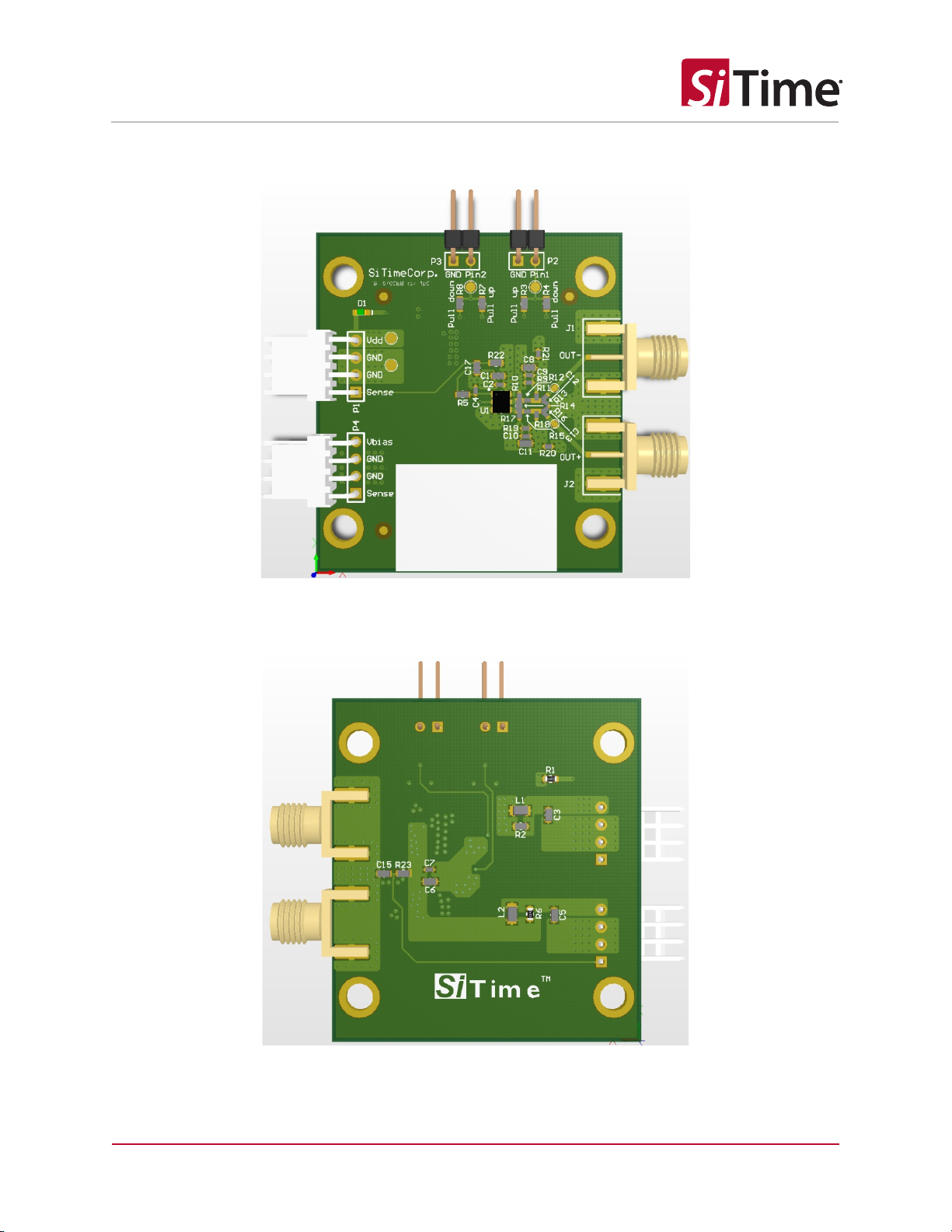
Appendix C – Board View
Figure 8: SiT6760EB rev 1.0 – Top view
Figure 9: SiT6760EB rev 1.0 – Bottom view

SiT6760EB UM Rev 1.0 | Preliminary
Page 11 of 11
www.sitime.com
SiT6760EB Evaluation User Manual
Table 3. Revision History
Version
Release Date
Change Summary
1.0 Nov 10, 2020 Preliminary version
SiTime
Corporation, 5451 Patrick Henry Drive, Santa Clara, CA 95054, USA | Phone: +1-408-328-4400 | Fax: +1-408-328-4439
© SiTime Corporation,
December 2020. The information contained herein is subject to change at any time without notice. SiTime assumes no responsibility or
liability for
any loss, damage or defect
of a Product which is caused in whole or in part by (i) use of any circuitry other than circuitry embodied in a SiTime produc
t, (ii) misuse or abuse
including static discharge, neglect or accident, (iii) unauthorize
d modification or repairs which have been soldered or alte
red during assembly and are not capable of being tested
by SiTime under its normal test conditions, or (iv) improper installation, storage, handling, warehousing or transportation,
or (v) being sub
jected to unusual physical, thermal, or
electrical stress.
Disclaimer:
SiTime makes no warranty of any kind, express or implied, with regard to this material, and specifically disclaims any and al
l express or implied warranties, either in
fact or by opera
tion of law, statutory or otherwise, including the implied warranties of merchantability and fitness for use or a particular purpose, and any implied warranty
arising
from
course of dealing or usage of trade, as well as any common-law duties relating to accuracy or lack of negligence, with respect to this material, any SiTime product and
any
product
documentation. Products sold by SiTime are not suitable or intended to be used in a life support application or component, to operate nuclear facilities, or in
other
mission
critical applications where human life may be involved or at stake. All sales are made conditioned upon compliance with the critical uses policy set forth below.
CRITICAL USE EXCLUSION POLICY
BUYER AGREES NOT TO
USE SITIME'S PRODUCTS FOR ANY APPLICATION OR IN ANY COMPONENTS USED IN LIFE SUPPORT DEVICES OR TO OPERATE NUCLEAR FACILITIES
OR
FOR
USE IN OTHER MISSION-CRITICAL APPLICATIONS OR COMPONENTS WHERE HUMAN LIFE OR PROPERTY MAY BE AT STAKE.
SiTime owns all righ
ts, title and interest to the intellectual property related to SiTime's products, including any software, firmware, copyright
, patent, or trademark. The sale of
SiTime products does not convey or imply any license under patent or other rights. SiTime retains the copyright and trademark rights in all documents, catalogs and plans
supplied pursuant to or ancillary to the sale of products or services by SiTime. Unless otherwise agreed to in writing by SiTime, any reproduction, modification, translation,
compil
ation, or representation of this material shall be strictly prohibited.
Table of contents
Other SiTime Motherboard manuals

SiTime
SiTime SiT6502EB User manual

SiTime
SiTime SiT6722EB User manual

SiTime
SiTime SiT92216 User manual

SiTime
SiTime SiT6098EBB User manual

SiTime
SiTime SiT6731EB User manual

SiTime
SiTime SiT6503EB User manual

SiTime
SiTime SiT92113 User manual

SiTime
SiTime SiT6731EB User manual

SiTime
SiTime Time Machine II User manual

SiTime
SiTime Time Machine II User manual


Popular Motherboard manuals by other brands

EastRising
EastRising ER-DBT018-3 user guide

DMP Electronics
DMP Electronics RoBoard RB-100 manual

MSI
MSI Z370 GAMING PLUS manual

Freescale Semiconductor
Freescale Semiconductor TWR-K60N512-KEIL quick start guide

Asus
Asus PRIME H310M-AT quick start guide

ON Semiconductor
ON Semiconductor NCD9830GEVB user manual


