V2 ELETTRONICA PD2 User manual

26
INDEX
PROGRAMMING .............................................................................................................. 28
CONTROL PANEL ....................................................................................................... 28
PROGRAMMING ......................................................................................................... 29
FUNCTION OF THE BUTTONS, MENU, UP and DOWN ........................................ 29
STANDARD PROGRAMMING (DEFAULT)............................................................. 29
PERSONALIZED PROGRAMME ............................................................................... 30
OPENING TIME ........................................................................................................... 30
OPENING TIME OF PEDESTRIAN GATE ................................................................ 30
CLOSING TIME............................................................................................................ 30
CLOSING OF PEDESTRIAN GATE ........................................................................... 31
PRE-FLASHING TIME................................................................................................. 31
MOTOR POWER .......................................................................................................... 31
START OFF................................................................................................................... 32
START IN OPENING ................................................................................................... 32
START IN CLOSING.................................................................................................... 32
START IN PAUSE ........................................................................................................ 33
PEDESTRIAN START IN OPENING .......................................................................... 33
THE PHOTOCELL IN PAUSE..................................................................................... 33
AUTOMATIC CLOSING ............................................................................................. 34
COURTESY LIGHTS ................................................................................................... 34
FLASHLIGHT IN PAUSE ............................................................................................ 36
FLASHLIGHT WITH INTERMITTENCE................................................................... 36
GB
27
INDEX
CLOCK FUNCTION ..................................................................................................... 36
BRAKE .......................................................................................................................... 37
INPUT STOP ................................................................................................................. 37
INPUT PHOTO 1........................................................................................................... 37
INPUT PHOTO 2........................................................................................................... 38
INPUT SAFETY RIB 1 ................................................................................................. 38
INPUT SAFETY RIB 2 ................................................................................................. 39
INPUT LIMIT SW. OPEN ........................................................................................... 39
INPUT LIMIT SW CLOSE ........................................................................................... 39
RADIO INPUTS ............................................................................................................ 40
INPUT RADIO 1 (tEL1)............................................................................................... 40
INPUT RADIO 2 (tEL2)............................................................................................... 40
INPUT RADIO 3 (tEL3)............................................................................................... 41
INPUT RADIO 4 (tEL4)............................................................................................... 41
END OF PROGRAMMING .......................................................................................... 41
INSTRUCTION FOR THE INSTALLATION .................................................................. 42
WARNING LIGHT DESCRIPTION ................................................................................. 42
TERMINAL CONNECTIONS........................................................................................... 42
TECHNICAL SPECIFICATIONS ..................................................................................... 43
FUNCTION CHART.......................................................................................................... 44
FUNCTION TABLE PD2 .................................................................................................. 47
PCB AND CONNECTIONS .............................................................................................. 49
GB

CONTROL PANEL
First of all make the connections mentioned
above before switching on the power station.
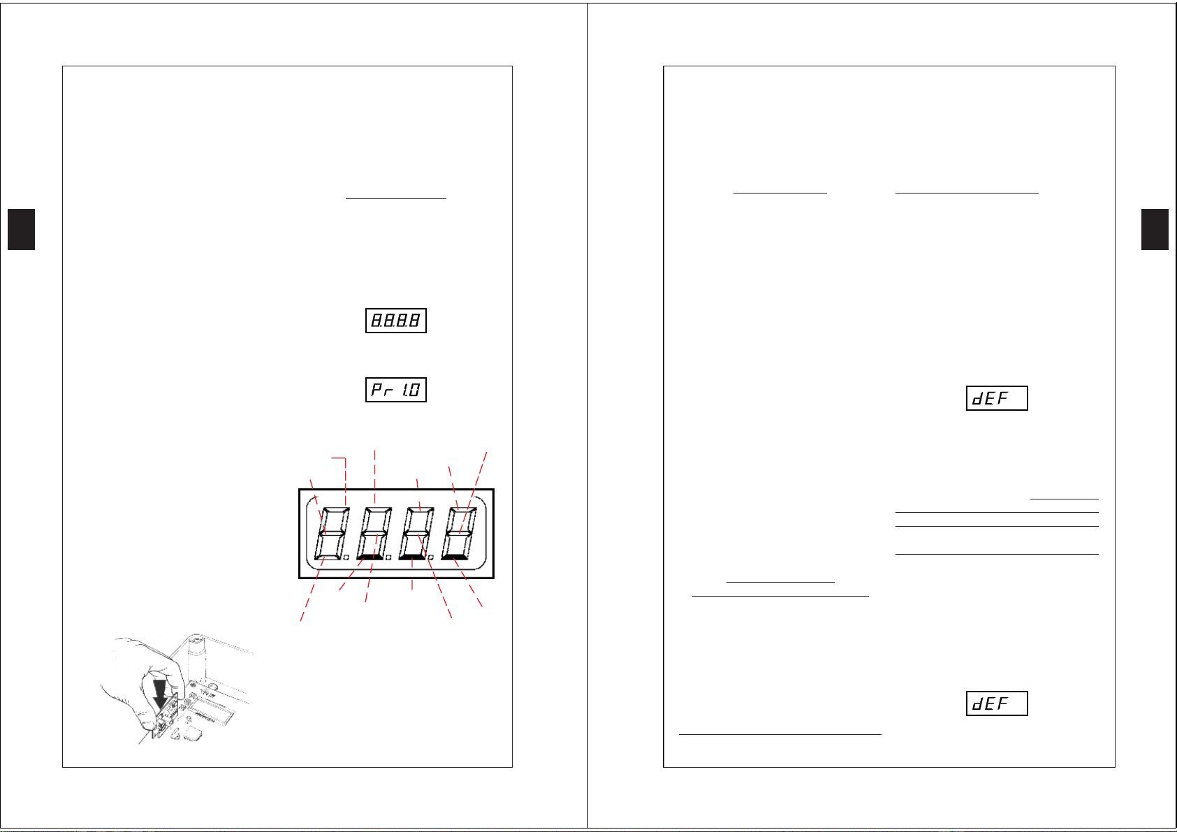
The power station will check DISPLAY 's
correct functioning activating the different
sections for 1,5 seconds
Afterthis, onthe displayappears thesoftware
version for 1,5 seconds. Example:
The display shows the control panel:
START P. LIMIT-SW. OPEN
START PHOTO 1
PHOTO 2 STOP
UP DOWN
SAFETY-RIB 1 MENU
LIMIT-SW. CLOSE SAFETY-RIB 2
The control panel shows the actual state of
the contacts and programming keys: if the
contact is closed the higher section is
illuminated, if the contact is open, the lower
section is illuminated. The drawing above
illustrates the case where no input has been
connected.
PROGRAMMING
28
The new PD2 electronic programmer,
designed and carried out by V2 ELETTRO-
NICA,finds itsapplication in theinstallations
of automated sliding gates with the utmost
reliability and safety.
Thanks to the versatility of this product, it is
possible to satisfy all requirements with
functionality and efficiency.
PD2 is equipped with a display which
enables, besides an easy programming, the
constant monitoring of the inputs'state;
furthermore, its menu structure enables a
simple layout of the working times and
function logics. It is built by a sophisticated
surface assembly technique and it is
characterized by the complete electrical
isolation between the digital circuit and the
power. According to the safety standard UNI
8612, it is equipped with an electronic torque
regulator. The presence on board of a quick
inputconnector enablesthe inputof amodule
receiver of the series MT or MQ: it is
therefore possible to employ the four
available radio channels, associated to the
controls: START, PEDESTRIAN START,
STOP and ACTIVATION AUXILIARY
EXIT.
Furthermore, this control unit is equipped
with an output for the connection of the pilot
lamp indicating the state of the gate, and an
output to control the switching on and off of
the courtesy lights.
PLUG-IN RECEIVER INSERTION
GB
PROGRAMMING
29
PROGRAMMING
PD2has a menuprogramming structure. Each
menu corresponds to a function of the unit
(functionmenu) or to the setting of a working
time(time menu). The time menus enable the
adjustment of the unit's working times (Ex.:
opening or closing time, pre-flashing time,
etc.) and can be set from 0 to 120 seconds
by a scanning of ±0,5 s. On the other hand,
the function menus enable the activation of
the wished functions (Ex: timed courtesy
lights, PHOTO2 disconnected, active
automatic closing, etc.).
There are a few time menus depending on
specific function menus (Ex.: if the
AUTOMATIC CLOSING is activated, it is
necessary to set a STANDSTILL TIME, if
not connected, it is necessary to re-set it); in
order to facilitate the programming, these
timemenus have been put into a fewfunction
menus, on which they depend. Specifically
the menus: AUTOMATIC CLOSING
(Ch.AU), LIGHTS (LUCi), and
PHOTOCELL IN STANDSTILL (Ft.PA)
present among the various options a few time
menus.
FUNCTION OF THE
BUTTONS, MENU, UP and DOWN
Whenthe programming function is activated,
press the button UP or DOWN to select the
menus, by shifting forward or backward
(keep the button pressed for a quick shifting).
Press the button MENU to enter the settings
which can be modified by pressing the
buttons UP and DOWN.
WHEN THE PROGRAMMING
FUNCTION IS NOT ACTIVE, PRESSING
THE BUTTON UP CORRESPONDS TO
THE CONTROL START, PRESSING THE
BUTTON DOWN CORRESPONDS TO
THECONTROL PEDESTRIANSTART: IT
IS POSSIBLE TO CHECK THE SYSTEM
NOW.
Aftersupplying power, thedisplay mustshow
the control panel (make sure that the
connections are correct).
Keep the MENU button pressed until the
display shows:
Now the programming is activated: if within
1 minute no operation is carried out, the
programming goes automatically off
displaying again the control panel.
We can define the programming of the PD2
by two different ways: STANDARD
PROGRAMMING (DEFAULT) and
PERSONALIZED PROGRAMMING.
STANDARDPROGRAMMING(DEFAULT)
dEF is the Default program set by V2 Elet-
tronica. If you wish to memorize it, proceed
as follows.
Press MENU key: the display show no.
Press MENU key to confirm: the display
shows dEF.
Press DOWN key: the display shows FinE.
GB

PROGRAMMING
30
Press MENU key: the display shows no.
Select the option Si pressing UP or DOWN.
Press MENU key to confirm: the display
shows the control panel.
The default standard data have been
memorized and the control unti is ready to
be used.
PERSONALIZED PROGRAMME
This type of programme enables you to
change the working times and all the main
functions, according to the user's
requirements:by pressingUP orDOWN keys
is possible to select the wished menu (For a
quick shifting keep the key pressed. After the
amendment, press the key "END OF
PROGRAMMING" and quit: the new data
has been memorized.
ATTENTION: in case no inputs are made for
more than 1 minute, the control box goes
automatically out from the programme and
the amendment are not memorized.
OPENING TIME
Thismenu is adjustablefrom 0to 120 seconds
(±0,5) and determines the time for the
opening of the gate.
Press UP or DOWN keys, until the display
shows:
Press the MENU key, the display shows:
Set the wished time pressing the UP or
DOWN keys.
Press the MENU key to confirm:the display
shows the writing: t.AP.
OPENINGTIMEOFPEDESTRIANGATE
This menu is adjustable from 0 seconds to
t.AP (±0,5) and determines the opening time
of gate.
Press UP or DOWN keys, until the display
shows:
Press the MENU key, the display shows:
Set the wished time pressing the UP or
DOWN keys.
Press the MENU key to confirm:the display
shows the writing: t.APP.
CLOSING TIME
This menu is adjustable from 0 to 120
seconds(±0,5) which is the closing time for
gate. To avoid the uncompleted closing of
the gate, we suggest to set a longer opening
time of t.AP.
GB
PROGRAMMING
31
Press UP or DOWN keys, until the display
shows:
Press the MENU key,the display shows:
Set the wished time pressing the UP or
DOWN keys.
Press the MENU key to confirm:the display
shows the writing t.Ch.
CLOSING OF PEDESTRIAN GATE
This menu is adjustable from 0 to t.Ch (±0.5)
and determines the closing time of gate. In
order to avoid the uncompleted closing of the
gate, we suggest to set a longer opening time
of t.APP.
Press UP or DOWN keys, until the display
shows:
Press theMENU key, the display shows:
Set the wished time pressing the UP or
DOWN keys.
Press the MENU key to confirm: on the
display will appear: t.ChP.
PRE-FLASHING TIME
This menu permits the introduction of a pre-
flashing that occurs before any movement of
the gate either in opening or in closing phase:
the time of pre-flashing can be adjusted from
0 to 120 seconds (± 0,5).
Press the keysUP orDOWN until the display
shows:
Press the MENU key,the display shows:
Set the wished time pressing the UP or
DOWN keys.
Press the MENU key to confirm, on the
display will appear t.PrE.
MOTOR POWER
This menu permits to adjust the motor power
from 30 to 100% with a scanning of ±0,5.
Press the keysUP orDOWN until the display
shows:
Press the MENU key,the display shows:
Set the wished value pressing the UP or
DOWN keys.
GB

PROGRAMMING
32
Press the MENU key to confirm, on the
display will appear Pot.
START OFF
When the gate is at a standstill and is going
tomove, itis contrasted bythe startinginertia.
As a consequence of this, if the gate is very
heavy the gates might not move. By
activating the start off function, it is possible
to win the initial inertia thanks to the motor
start to the maximum of the power for 2
seconds.
Press the keysUP orDOWN until the display
shows:
Press the MENU key,the display shows one
of the 2 writings:
no the motor start to the maximum the
power is not activated.
Si the motor start to the maximum the
power is activated.
Set the wished functions pressing the UP or
DOWN keys.
Press the MENU key to confirm, on the
display will appear SPUn.
START IN OPENING
This menu permits to select the functions of
start during the opening phase.
Press the keysUP orDOWN until the display
shows:
Press the MENU key, the display shows one
of the 3 writings:
no the command START is not
available.
ChiU the command START clouse the
gate.
PAUS the command START stop the gate
and goes into in PAUSE.
Set the wished functions pressing the UP or
DOWN keys.
Press the MENU key to confirm, on the
display will appear St.AP
START IN CLOSING
This menu permits to select the functions of
start during the closing phase.
Press the keysUP orDOWN until the display
shows:
Press the MENU key, the display shows one
of the 2 writings:
StoP the command START stop the gate
APEr the command START open the gate
Press the MENU key,the display shows one
of the 2 writings.
GB
PROGRAMMING
33
Press the MENU key to confirm, on the
display will appear St.Ch.
START IN PAUSE
This menu permits to select the functions of
the command start during the standstill.
Press the keysUP orDOWN until the display
shows:
Press the MENU key, the display shows one
of the 2 writings:
no the command START is not
available. THIS FUNCTION
CANNOT BE SELECTED UNTIL
THE AUTOMATIC CLOSING
HAS BEEN ACTIVATED (menu
Ch.AU).
ChiU the command START closes the
gate.
Set the wished functions pressing the UP or
DOWN keys.
Press the MENU key to confirm, on the
display will appear St.PA.
PEDESTRIAN START IN OPENING
This menu permits to select the functions of
the command of START P. during the
opening phase.
Press the keysUP orDOWN until the display
shows:
Press the MENU key,the display shows one
of the 3 writings:
PAUS the command PEDESTRIAN
START stops the gate and goes in
PAUSE.
no the command PEDESTRIAN
START is not available
ChiU the command PEDESTRIAN
START closes the gate.
Set the wished functions pressing the UP or
DOWN keys.
Press the MENU key to confirm, on the
display will appear SP.AP.
THE PHOTOCELL IN PAUSE
This menu permits to determine the
functioning of two photocells during the
pause phase.
Press the keysUP orDOWN until the display
shows:
Press the MENU key,the display shows one
of the 2 writings:
rPAU the interrruption of the photocell's
ray causes the top of the pause time;
when the photocells work again, the
pause time restart from zero;
t.PCh the interrruption of the photocell's
ray causes the top of the pause time;
GB

PROGRAMMING
34
when the photocells work again,the
gate stops for a time to be set
between 0 to 120 seconds.
Set the wished functions pressing the UP or
DOWN keys.
Press the MENU key to confirm.
If the function is t.PCh, the display shows:
Press the button UP or DOWN to program
the whished time.
Press the MENU key to confirm, on the
display will appear: Ft.PA.
If the function is rPAU, on the display will
appear: Ft.PA.
AUTOMATIC CLOSING
Permits the selection between the
semiautomatic or automatic functioning. By
the semiautomatic functioning the command
of START or PEDESTRIAN START opens
the gate, when the opening is complete the
gate remains still until the successive
command of opening, which will reclose it.
On the other hand, it stops automatically and
remains in pause phase for the set time
(t.PAU), then it closes again through the set
closing time. If the cycle is started with a
START, the control unit ignores the
command START P. until the end of the
cycle. The in pause time is adjusted from 0
to 999 seconds.
Press the MENU key to confirm, on the
display will appear:
Press the MENU key,the display shows one
of the 2 writings:
no the automatic reclosing is not
available,the gate is semiautomatic.
t.PAU the reclosing is available, the
standstill time is set from 0 to 999.
Set the wished functions pressing the UP or
DOWN keys.
Press the MENU key to confirm
If the function is t.PAU, the display shows:
Set the wished time pressing the UP or
DOWN keys.
Press the MENU key to confirm, on the
display will appear Ch.AU.
If the function is no, on the display will
appear: Ch.AU.
IMPORTANT:If the automatic reclosing is
not available, it is necessary to have the
command START in PAUSE menu St.PA).
COURTESY LIGHTS
Thanks to the connection "warning light" the
GB
PROGRAMMING
35
PD2 control unit enables the connection of
the courtesy lights (I.E. garden lights), which
can work automatically (lights on for the
whole cycle) or timed (lights on for a time
adjustable from 0 to 999 seconds). The lights
turn on with a START or PEDESTRIAN
START control. It is also possible to control
this connection using the code memorized in
the radio input tEL4, in this last case the
connection "warning light" becomes an
auxiliary connection to which it is possible
to match one of the following functional
logics:
monostable: it activates the output relay
through all the tx transmission time, when
the transmission ends the relay is
disconnected.
bistable:it activates the relay with thetx first
transmission, the relay disconnects with the
second transmission.
timer: the tx transnission triggers the relay
which disconnects automatically after a time
adjustable between 0 and 999 seconds.
Press the keysUP orDOWN until the display
shows:
Press the MENU key,the display shows one
of the 3 writings:
t.LUC the courtesy lights start from a time
adjustable from 0 to 999 seconds.
CiCL the courtesy lights are on through
the whole cycle.
AUS auxiliaryexit withadjustable logical
functioning.
Set the wished functions pressing the UP or
DOWN keys.
Press the MENU key to confirm
If the function selected is AUX, one of the
following will appear on the display:
tiM timedauxiliary exit (time adjustable
from 0 to 999 seconds)
biSt auxiliary output relay with bistable
functioning
Mon auxiliary output relay with
monostable functioning
Press the UP or DOWN keys to select the
wished function.
Press the MENU key to confirm.
If the selected function istiM, on the display
will appear:
Press the UP or DOWN keys to select the
wished time.
Press the MENU key to confirm, on the
display will appear: LUCi.
If the selected function is biST or Mon on
the display will appear LUCi.
If the function is t.LUC, on the display will
appear:
Press the UP or DOWN keys to select the
wished time.
GB

PROGRAMMING
36
Press the MENU key to confirm, on the
display will appear: LUCi.
If the function is CiCL, on the display will
appear: LUCi.
FLASHLIGHT IN PAUSE
Thismenu permitsto activate orto disactivate
the flashlight during the pause time.
Press the keysUP orDOWN until the display
shows:
Press the MENU key,the display shows one
of the 2 writings:
no not activated flashlight in pause
Si activated flashlightin in pause
Press the MENU key,the display shows one
of the 2 writings.
Press the MENU key to confirm, on the
display will appear: LP.PA.
FLASHLIGHT WITH
INTERMITTENCE
The control unit PD2 permits the connection
ofa flashlightwith or withoutintermittence.If
the flashlight is equipped with an inner
intermittence effect, it is necessary to select
the option "Si", but if it has no inner
intermittence, it is necessary to select the
option "no" in oder to make it flash.
Press the keysUP orDOWN until the display
shows:
Press the MENU key,the display shows one
of the 2 writings.
no if the flashlight has no inner
intermittence
Si the clock function is activated
Set the wished functions pressing the UP or
DOWN keys.
Press the MENU key to confirm, on the
display will appear: in.LP.
CLOCK FUNCTION
This function permits to program the time
bands of opening and closing. It is necessary
to connect a 24h timer with a contact
normally open in parallel with the START
or PEDONAL START input. When the ti-
mer contact is closed, the gate gets into
opening phase and remains opened until the
contact of the timer opens causing the
re-closing of the gate.
IMPORTANT: FOR A CORRECT
FUNCTIONING IT IS NECESSARY TO
ACTIVATETHE AUTOMATICCLOSING
(menu Ch.AU.)
Press the keysUP orDOWN until the display
shows:
Press the MENU key,the display shows one
of the 2 writings:
GB
PROGRAMMING
37
no the clock function is not activated
Si the clock function is activated
Set the wished functions pressing the UP or
DOWN keys.
Press the MENU key to confirm, on the
display will appear oroL.
BRAKE
This menu enables the activation of the brake
function by which it is possible to avoid
unproper motion of the gate after impulse or
safety intervention ( the gate continues
moving instead of immediately stopping).
This inconvenience occurs when a plate-
clutch motor is employed on a very heavy
gate: because of the inertia, the gate does not
stop immediately but keeps moving for a few
dozens centimetres undermining its safety.
PressUP orDOWN, until the display shows:
Press MENU, the display shows:
no the brake function is disconnected
Si the brake function is activated
PressUPorDOWNtoselectthewishedfunction.
Press MENU to confirm: the display
shows: FrEn.
INPUT STOP
This menu permits to select the functions
associated to the command of STOP.
Press the UP or DOWN keys until on the
display appears:
Press the MENU key,the display shows one
of the 3 writings:
no the input STOP is not available
ProS the input STOP stops the gate:
pressing the command START the
gate continues the motion
invE the command STOP stops the
gate: at the next START the gate
starts moving in the opposite
direction.
NOTE: During the pause STOP stops the
gate: pressing the command START will
always re-closing the gate.
Press UP or Down to select the wished
function.
Press menu to confirm. the display shows
StoP.
INPUT PHOTO 1
The photocell 1 (contact normally closed) is
asafety device whichis activeduring opening
and closing: the intervention of the photocell
during the closing halts the gate, after the
photocell is cleared the gates reverses the
GB

PROGRAMMING
38
movement. On the other hand, the
intervention of the photocell during opening
halts the gate, when the photocell is cleared
the gate re-starts opening. It is necessary to
install photocell 1 in a proper way, to make
it cover the gate's action ray.
Press theUP orDOWN keys until the display
shows:
Press the MENU key,the display shows one
of the 2 writings:
no the opening of PHOTO1 is not
available
APCh the opening of PHOTO 1 is
available for the connection of the
photocell
Set the wished functions pressing the UP or
DOWN keys.
Press the MENU key to confirm, on the
display will appear Fot1.
INPUT PHOTO 2
The photocell 2 is active in closing: if it is
dimmed during the closing it stops the gate
and inverts the motion. The option CFCh
activates the photocell even when the gate is
still: closed gate means that no impulse has
been given, either it is in pause or it has
received a STOP command. In this case
through all the time of the darkening of the
photocell the control unit does not receive
any command of activation at any opening/
closing cycle.
Press the UP or DOWN keys until on the
display appears:
Press the MENU key,the display shows one
of the 3 writings:
no the input PHOTO 2 is not available
CFCh the input PHOTO 2 is available: the
photocell is active in closing and
also when the gate is still
Ch the input PHOTO 2 is available: the
photocell is active only during the
closing
Set the wished functions pressing the UP or
DOWN keys.
Press the MENU key to confirm, on the
display will appear Fot 2.
INPUT SAFETY RIB 1
Theinput SAFETY RIB 1 (contact normallly
closed) enables the connection of the rib,
active safety during opening and closing. Its
intervention during opening halts the gate,
reverses its motion for 3 seconds and blocks
it: next START or START P restores the
opening. On the other hand, the intervention
of the rib 1 during closing blocks the gate:
the next START or START P. restores the
closing.
PressUP orDOWN, until the display shows:
GB
PROGRAMMING
39
Press MENU, the display shows either:
no the input COS 1 is disconnected.
Si the input COS 1 is activated for the
connection of the rib.
Press UP or DOWN to choose the wished
function.
Press MENU to confirm, the display shows:
Cos 1.
INPUT SAFETY RIB 2
The input SAFETY RIB 2 (contact normally
closed) enables the connection of the safety
rib, safety activeduring opening and closing.
Its intervention during the closing halts the
gate reverses the motion for 3 s and blocks
it: the next START or START P. restores the
closing motion. On the other hand, the
intervention of the rib 2 during opening halts
the gate and blocks it: the next START or
START P. restores the openig motion.
PressUP orDOWN, until the display shows:
Press MENU, the display shows one of the
two writings:
no the input COS 2 is disconnected.
Si the input COS 2 is activated
for the connection of the safety rib.
Press UP or DOWN to select the wished
function.
Press MENU to confirm, the display shows:
CoS 2.
INPUT LIMIT SW. OPEN
This input (contact normally closed) enables
the connection of a limit switch which can
be magnetic or micro-switch. This safety
deviceisconnected duringthe openingphase:
its intervention halts the gate and prevents it
from coming out from the rail.
PressUP orDOWN, until the display shows:
Press MENU, the display shows one of the
two writings:
no the input LIMIT SW. OPEN is
disconnected.
Si the input LIMIT SW. OPEN is
activated for the connection of the
limit switch active during opening.
Press UP or DOWN to choose the wished
function.
Press MENU to confirm, the display shows:
FCA.
INPUT LIMIT SW CLOSE
The input LIMIT SW. CLOSE (contact
normally closed) enables the connection of
the limit switch which can be magnetic or
micro-switch. This safety device is active
during the closing motion : its intervention
halts the gate and prevents it from going out
from the rail.
GB

PROGRAMMING
40
PressUP orDOWN, until the display shows:
Press MENU, the display shows one the two
writings:
no the input LIMIT SW. CLOSE is
disconnected.
Si the input LIMIT SW. CLOSE is
activated for the connection of the
limit switch active during closing.
Press UP or DOWN to choose the wished
function.
Press MENU to confirm, the display shows:
FCC.
RADIO INPUTS
The PD2 control unit enables to plug in a
superreactive or quarzed module receiver of
the MT or MQ series. It has 4 radio-channels
in which four codes must be memorized.
They must all belong to the same standard
(53200, K and KF).
Each of the four radio channels tEL1, tEL2,
tEL3 tEL4 is associated to a function of the
unit: :
tEL1 →START transmitting the code
associated to tEL1, the control unit
receives a START
tEL2 →PEDESTRIAN START
transmitting the code associated to
tEL2, the control unit receives a
PEDESTRIAN START
tEL3 →STOP transmitting the code
associated totEL3, the control unit
receives a STOP
tEL4 →AUXILIARY OUTPUT by
transmitting the code memorized in
tEL4, the unit activates the relay of
auxiliary output.
INPUT RADIO 1 (tEL1)
PressUP orDOWN, until the display shows:
Press MENU, the display shows:
Press and keep pressed the button of the
transmitter to be memorized.
If the code has been properly memorized the
display shows:
Release the button, the display shows:tEL1.
Ifyou try toinput an alreadymemorized code,
the display shows the channel in which it is
memorized (Ex.: tEL3).
INPUT RADIO 2 (tEL2)
PressUP orDOWN, until the display shows:
GB
PROGRAMMING
41
Press MENU, the display shows:
Press and keep pressed the button of the
transmitter to be memorized.
If the code has been correctly memorized the
display shows:
Release the button, the display shows:tEL2.
Ifyou try toinput an alreadymemorized code,
the display shows the radio channel where it
has been memorized (Ex.: tEL4).
INPUT RADIO 3 (tEL3)
PressUP orDOWN, until the display shows:
Press MENU, the display shows:
Press and keep pressed the button of the
transmitter to be memorized.
If the code has been correctly memorized the
display shows:
Release the button, the display shows:tEL3.
Ifyou try toinput an alreadymemorized code,
the display shows the channel where it has
been memorized (Ex.: tEL1).
INPUT RADIO 4 (tEL4)
PressUP orDOWN, until the display shows:
Press MENU, the display shows:
Press and keep pressed the button of the
receiver to be memorized.
Ifthe code has been correctly memorized, the
display shows:
Release the button , the display shows:tEL4.
ifyou try toinput analready memorized code,
the display shows the channel where it has
been memorized (Ex.: tEL2).
NOTE: if the code to memorize into one of
the four channels is not correctly learned, the
display keeps showing trAS. The error may
have been caused by incompatibility of the
code's type, or wrong reception. In this latter
case try to memorize again.
END OF PROGRAMMING
This menu allows to finish the programming
(both default and personalized) saving the
modified data into memory.
Press the UP or DOWN keys until on
GB

the display appears:
Press the MENU key to confirm, one of the
following will appear on the display:
no further corrections to carry out: do
not quit the programming
Si end of programming
Press the UP or DOWN keys to select the
wished function.
Press the MENU key to confirm.
If the function is no, on the display will
appear: FinE.
By pressingUP orDOWN you can scroll the
menus to make modifications.
Ifthe function isSi, onthe displaywill appear
the control panel.
The inserted data have been memorized: the
control unit is ready to be used.
INSTRUCTIONS FOR
THE INSTALLATION
The installer must provide for a device (es.
magnetotermical switch) ensuring the
omnipolar sectioning of the
PD2 equipment from the power
supply.
The standards require a separation of the
contacts of at least 3 mm in each pole (CEI
EN 60335-1).
PROGRAMMING
42
The equipment is designed for non enclosed
installations.
For the connection of stiff or flexible tubes
and fasteners, use connectors according to
IP55 protection grade.
WARNING LIGHT DESCRIPTION
The warning light shows in real time
the state of the gate:
STOP →light off
IN PAUSE →light always on
DURING OPENING →the light flashes
slowly (2 Hz)
DURING CLOSING →the light flashes
rapidly (4 Hz)
TERMINAL CONNECTIONS
Inorder to facilitate the connections, the PD2
control unit is equipped with two entirely
removable terminal blocks.
1. Antenna masquade.
2. Antenna shield.
3. Opening control for the connection
of: push-button panel, key switch
and timer. Contact normally open.
4. Pedestrian opening control for the
connection of:: push-button panel,
key switch and timer. orologio.
Contact normally open.
5. Stop. Contact normally closed.
6. Common (-).
GB
PROGRAMMING
43
7. Photocell 1. Contact normally
closed.
8. Photocell 2. Contact normally
closed.
9. Safety bar 1. Contact normally
closed.
10. Safety bar 2. Contact normally
closed.
11. Common(-).
12. Limit switch during opening.
Contact normally closed.
13. Limitswitch during closing.Contact
normally closed.
14.-15. Output power supply 24 Vac for
photocells and other accessories.
16.-17. Pilot lamp 24 Vac 3W.
18.-19. Flashlight 220 Vac 40 W.
20.-21. Contact for courtesy light 220 Vac
10 A.
22. Output motor opening.
23. Common motor.
24. Output motor closing and
connection of the rephasing
capacitor
25. Terminal for the connection of the
rephasing capacitor.
26. Neutral power supply 230 Vac.
27. Power supply phase 230 Vac.
IMPORTANT: it is necessary to connect the
rephasingcapacitor betweenthe terminals 24
and 25.
GB
TECHNICAL SPECIFICATIONS
Power supply: 230 Vac; 50Hz
Max motor load: 700 W
Max load accessories
powered at 24V: 10 W
Working environment
temperature: -20°C / +60°C
Protection fuses:5A for line 230Vac
400mA for line 24Vac
Dimensions: 220x170x80 mm
Weight: 1,65 Kg

FUNCTION CHART
44
For the use of the function chart
proceed as follow:
- press DOWN key to flow the
chart from the top to the bottom.
The functions dEF, t.AP1, t.AP2
etc.. will be appear.
- press UP key to flow the chart
from the bottom to the top;
- press MENU key to flow the
chart horizontally; for example, if
the t.ChP function is displayed, by
pressing the MENU key the
number 7.0 will be dispayed.
Increase the number pressing UP
or DOWN. Press MENU to display
function t.ChP again.
GB
FUNCTION CHART
45
GB

FUNCTION CHART
46
GB
FUNCTION TABLE PD2
47
N. DISPLAY DATAS DESCRIPTION DEFAULT
DATAS MEMO
DATAS
0dEF no/Si Load V2 standard datas no
1t.AP 0 - 120 s Opening time 22.5
2t.APP 0 - t.AP1 Opening time of pedestrian gate 6.0
3t.Ch 0 - 120 s Closing time 23.5
4t.ChP 0 - t.Ch1 Closing time of pedestrian gate 7.0
5t.PrE 0 - 120 s Pre-flashing time 1.0
6Pot. 30 to 100% Motor power 40
7SPUn no/Si Start off Si
8St.AP no
ChiU
PAUS
Start in opening
- START command is not available
- command close the gate
- stop the gate and goes in Pause
PAUS
9St.Ch Stop
APEr
Start in closing
- command START stop the gate
- command START open the gate
StoP
10 St.PA no
chiU
Start in pause
- START command is not available
- START command closes the gate
ChiU
11 SP.AP no
ChiU
PAUS
Pedestrian in opening
- P START command is not available
- P START closes the gate
- gate goes in pause
PAUS
12 Ft.PA rPAU
t.PCh
Photocell in pause
- Pause time recharged
- gate stop for a time to be set
between 0 to 120 seconds
r.PAU
GB

FUNCTION TABLE PD2
48
N. DISPLAY DATAS DESCRIPTION DEFAULT
DATAS MEMO
DATAS
13 Ch.AU no
t.PAU
Automatic closing
- automatic closing not available
- reclosing is available, the standstill time is set
from 0 to 999 s
No
14 LUCi CiCL
t.LUC
AUS
timer
bISt
Mon
Courtesy light
- lights are on trough the whole cycle
- lights start time adjustable from 0 to 999 s
- auxiliary output
--- timed aux out (from 0 to 999 s)
--- aux out relay with bistable functionning
--- aux out relay with monostable functionning
t.LUC
=60 s
15 LP.PA no/Si Flashlight in pause no
16 In.LP no/Si Flashlight with intermittence no
17 OroL no/Si Clock function no
18 FrEn no/Si Brake no
19 StoP no
invE
.
ProS
Input STOP
- input STOP not available
- input STOP stops the gate: pressing the
command START gate continues the motion
- STOP command stops the gate: START
command starts moving in the opposite direction
no
20 Fot 1 no
APCh
Input PHOTO 1
- not available
- photocell active during the opening & the closing
no
21 Fot 2 no
CFCh
.
Ch
Input FOTO 2
- not available
- input available: photocell is active in closing and
also when the gate is still
- input available: photocell active during the
closing
CFCh
22 CoS1 Si/no SAFETY RIB1 input Si
23 Cos2 Si/no SAFETY RIB2 input Si
24 FCA Si/no LIMIT SW. OPEN input Si
25 FCC Si/no LIMIT SW CLOSE input Si
26 tEL 1 Radio input associated to START command
27 tEL 2 Radio input associated to Ped START command
28 tEL 3 Radio input associated to STOP command
29 tEL 4 Radio input associated to courtesy light
30 Fine no/Si End of programming no
GB
49
PCB AND CONNECTIONS
NOTEFor the connection of the cables to the clamp, use the plastic
small band for the cables connected with the accessories and
for the cables connected with the supply power
GB
Table of contents
Popular Motherboard manuals by other brands

Broadcom
Broadcom BCM91125E user manual

Systium Technologies
Systium Technologies Ready 113 User's quick start guide

Beckhoff
Beckhoff CB3063 manual

NavSpark
NavSpark RTK-EB1 quick guide

Texas Instruments
Texas Instruments TLV62585PEVM-030 user guide

Asus
Asus M3N-HT - Deluxe/HDMI Motherboard - ATX user manual