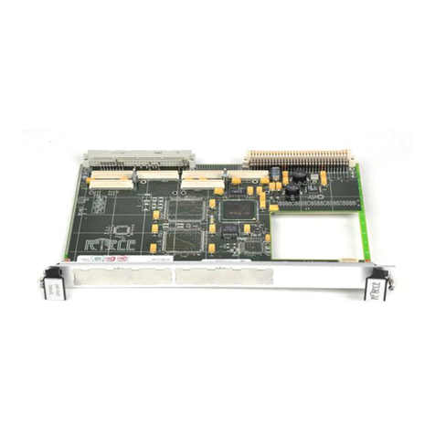
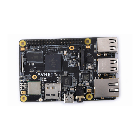
Actis VSBC-6872 Series User manual

-~
ARTISAN
®
~I
TECHNOLOGY
GROUP
Your definitive source
for
quality
pre-owned
equipment.
Artisan Technology
Group
Full-service,
independent
repair
center
with
experienced
engineers
and
technicians
on staff.
We
buy
your
excess,
underutilized,
and
idle
equipment
along
with
credit
for
buybacks
and
trade-ins
.
Custom
engineering
so
your
equipment
works
exactly as
you
specify.
•
Critical
and
expedited
services
•
Leasing
/
Rentals/
Demos
• In
stock/
Ready-to-ship
•
!TAR-certified
secure
asset
solutions
Expert
team
ITrust
guarantee
I
100%
satisfaction
All
tr
ademarks,
br
a
nd
names, a
nd
br
a
nd
s a
pp
earing here
in
are
th
e property of
th
e
ir
r
es
pecti
ve
ow
ner
s.
Find the ACTIS Computer VSBC-6872/FHE-A at our website: Click HERE

USER'S GUIDE
VSBC-6872 series
VMEbus Single Board Computer with
Freescale MPC8270 processor
Revision 1.4
3812
ACTIS Computer
www.actis-computer.com
suppor[email protected]
Artisan Technology Group - Quality Instrumentation ... Guaranteed | (888) 88-SOURCE | www.artisantg.com

Artisan Technology Group - Quality Instrumentation ... Guaranteed | (888) 88-SOURCE | www.artisantg.com

User's guide
http://support.actis-computer.com
3
Copyright statement: Copyright ©2000-2008 by ACTIS Computer, Switzerland.
All rights reserved. No part of this publication may be reproduced, transmitted, transcribed, stored in a
retrieval system, or translated into any language, in any form or by any means without the written
permission of ACTIS Computer.
Licenses and trademarks
All licenses and trademarks are property of their respective owners.
Disclaimer:
The information in this document has been carefully checked and is believed to be entirely reliable.
However, no responsibility is assumed for inaccuracies. ACTIS Computer does not assume any liability
arising out of the application or use of any product or circuit described herein; neither does it convey any
license under its patent rights nor the rights of others. ACTIS Computer products are not designed,
intended, or authorized for use as components in systems intended to support or sustain life, or for any
other application in which the failure of an ACTIS Computer product could create a situation where
personal injury or death may occur, including, but not limited to ACTIS Computer products used in
defense, transportation, medical or nuclear applications. Should the buyer purchase or use ACTIS
Computer products for any such unintended or unauthorized application, the buyer shall indemnify and
hold ACTIS Computer and its officers, employees, subsidiaries, affiliates, and distributors harmless
against all claims, costs, damages and expenses, and reasonable attorney fees arising out of, directly or
indirectly, any claim of personal injury or death associated with such unintended or unauthorized use,
even if such claim alleges that ACTIS Computer was negligent regarding the design or manufacture of
the part.
Printed in Switzerland.
Artisan Technology Group - Quality Instrumentation ... Guaranteed | (888) 88-SOURCE | www.artisantg.com

Artisan Technology Group - Quality Instrumentation ... Guaranteed | (888) 88-SOURCE | www.artisantg.com

User's guide
http://support.actis-computer.com
5
Table of Contents
1
Introduction ....................................................................................................................................13
1.1
Features....................................................................................................................................14
1.2
VSBC-6872 Block Diagram........................................................................................................15
1.3
Component location...................................................................................................................16
2
Getting started................................................................................................................................17
2.1
Unpacking instructions...............................................................................................................17
2.2
Hardware Configuration.............................................................................................................17
2.3
Base board configuration...........................................................................................................17
2.4
Expansion module installation....................................................................................................17
2.5
Board installation.......................................................................................................................17
2.6
ECMon monitor.........................................................................................................................18
3
Functional description.....................................................................................................................19
3.1
Freescale MPC8270 processor..................................................................................................19
3.2
SDRAM controller......................................................................................................................20
3.3
Memory Management Unit.........................................................................................................21
3.4
External Bus Controller..............................................................................................................21
3.5
FLASH Memory.........................................................................................................................22
3.6
SRAM Memory..........................................................................................................................22
3.7
Real Time Clock........................................................................................................................23
3.8
CompactFlash card interface.....................................................................................................24
3.9
Fast Ethernet communication ports............................................................................................25
3.10
SCC multi-protocol serial ports ..................................................................................................25
3.11
Interrupt controller.....................................................................................................................27
3.12
Direct Memory Access Controller...............................................................................................28
3.13
I
2
C serial interface bus...............................................................................................................28
3.13.1
VPD EEPROM (Vital Product Data)...................................................................................29
3.14
MPC8270 PCI bus.....................................................................................................................30
3.14.1
PMC expansion slot..........................................................................................................30
3.14.2
Dual S-ATA Controller.......................................................................................................30
3.15
VMEbus Interface......................................................................................................................31
3.15.1
60x-to-VME Bridge............................................................................................................31
3.15.2
VMEbus Master ................................................................................................................32
3.15.3
VMEbus Slave..................................................................................................................32
3.15.4
VMEbus Requester...........................................................................................................35
3.15.5
VMEbus Interrupter...........................................................................................................35
3.15.6
VMEbus Interrupt Handler.................................................................................................35
3.15.7
VMEbus Mailbox...............................................................................................................35
3.15.8
VMEbus System Controller ...............................................................................................36
3.15.9
Bridge DMA Controller......................................................................................................36
4
Bridge Registers.............................................................................................................................37
5
Board resources.............................................................................................................................57
5.1
Peripheral Chip Select...............................................................................................................57
5.2
Memory map.............................................................................................................................57
5.3
Interrupt sources .......................................................................................................................58
5.4
Multiplexed General Purpose I/O ports......................................................................................59
6
Technical Characteristics................................................................................................................61
7
Hardware description......................................................................................................................63
7.1
Front panel connectors..............................................................................................................63
7.1.1
Fast Ethernet port FCC1..FCC3........................................................................................63
7.1.2
Console port .....................................................................................................................64
7.1.3
Multi-protocol serial ports SCC1..SCC4.............................................................................65
7.2
Board jumpers...........................................................................................................................67
7.3
Serial Communication port jumpers...........................................................................................68
7.4
IEEE1149.1 Test Access Port, P11 Connector...........................................................................69
7.5
SPI/SMC2/I2C connector...........................................................................................................69
7.6
S-ATA ports...............................................................................................................................70
7.7
CompactFlash connector...........................................................................................................70
7.8
VMEbus P1 connector...............................................................................................................71
Artisan Technology Group - Quality Instrumentation ... Guaranteed | (888) 88-SOURCE | www.artisantg.com

VSBC-6872 series
ACTIS Computer
6
7.9
VMEbus P2 connector...............................................................................................................72
7.10
PCI Mezzanine Card (PMC)......................................................................................................73
7.10.1
Installing a PMC................................................................................................................73
7.11
PMC interface, J11 connector....................................................................................................74
7.12
PMC interface, J12 connector....................................................................................................75
7.13
PMC interface, J14 connector....................................................................................................76
8
Software description.......................................................................................................................77
8.1
ECMon commands....................................................................................................................77
8.1.1
Command line and syntax rules........................................................................................77
8.1.2
Command descriptions......................................................................................................78
9
Web resources...............................................................................................................................95
10
Ordering information.......................................................................................................................97
11
Sales department...........................................................................................................................99
12
Technical Support...........................................................................................................................99
12.1
Hardware and Software Assistance...........................................................................................99
13
OEM Warranty..............................................................................................................................101
13.1
RMA request...........................................................................................................................101
14
Index............................................................................................................................................103
Artisan Technology Group - Quality Instrumentation ... Guaranteed | (888) 88-SOURCE | www.artisantg.com

User's guide
http://support.actis-computer.com
7
List of figures
Figure 1 - VSBC-6872 photograph.........................................................................................................11
Figure 2 - Block diagram........................................................................................................................15
Figure 3 - Component location - top assembly........................................................................................16
Figure 4 - Freescale MPC8270 block diagram........................................................................................19
Figure 5 - RTC Snaphat
®
battery............................................................................................................23
Figure 6 - SCC block diagram................................................................................................................26
Figure 7 - SCC resistor networks location...............................................................................................26
Figure 8 - MPC8270 interrupt controller..................................................................................................27
Figure 9 - DMA block diagram................................................................................................................28
Figure 10 - 60x-to-VME Bridge block diagram........................................................................................31
Figure 11 - VME Slave window defined by VSBA24 ...............................................................................34
Figure 12 - VME Slave window defined by XSAV24 ...............................................................................34
Figure 13 - Front panel connectors.........................................................................................................63
Figure 14 - Fast Ethernet port connector................................................................................................63
Figure 15 - Console port connector........................................................................................................64
Figure 16 - Serial port connector............................................................................................................65
Figure 17 - Board jumpers......................................................................................................................67
Figure 18 - Serial port jumpers...............................................................................................................68
Figure 19 - Test Access Port connector..................................................................................................69
Figure 20 - S-ATA connector description................................................................................................70
Figure 21 - PMC module installation.......................................................................................................73
Artisan Technology Group - Quality Instrumentation ... Guaranteed | (888) 88-SOURCE | www.artisantg.com

Artisan Technology Group - Quality Instrumentation ... Guaranteed | (888) 88-SOURCE | www.artisantg.com

User's guide
http://support.actis-computer.com
9
List of tables
Table 1 - Console port setting ................................................................................................................18
Table 2 - SDRAM device organization....................................................................................................20
Table 3 - SDRAM initialization................................................................................................................20
Table 4 - MPC8270 reset word...............................................................................................................22
Table 5 - UPM initialization for CompactFlash........................................................................................24
Table 6 - Fast Ethernet assignment........................................................................................................25
Table 7 - SCC RS-485 removable resistor networks...............................................................................26
Table 8 - VPD EEPROM address...........................................................................................................29
Table 9 - VPD serial EEPROM structure ................................................................................................29
Table 10 - VPD options field...................................................................................................................29
Table 11 - PCI bus devices....................................................................................................................30
Table 12 - PMC-P4 to VME-P2 mapping................................................................................................30
Table 13 - UPM initialization for bridge access .......................................................................................31
Table 14 - VME Master addressing space mapping................................................................................32
Table 15 - Bridge registers accessible from VMEbus..............................................................................33
Table 16 - A24 Slave memory map........................................................................................................33
Table 17 - Bridge registers list................................................................................................................37
Table 18 - Chip Select assignment.........................................................................................................57
Table 19 - Memory map.........................................................................................................................57
Table 20 - Interrupt sources...................................................................................................................58
Table 21 - FCC interrupt.........................................................................................................................58
Table 22 - GPIO port A & B controller setting .........................................................................................59
Table 23 - GPIO port C & D controller setting.........................................................................................60
Table 24 - Fast Ethernet connector assignment......................................................................................63
Table 25 - Network status LEDs.............................................................................................................63
Table 26 - Console port pin assignment.................................................................................................64
Table 27 - User LEDs.............................................................................................................................64
Table 28 - Serial port pin assignment.....................................................................................................65
Table 29 - Board jumper configuration....................................................................................................67
Table 30 - Serial port jumper location.....................................................................................................68
Table 31 - Serial port jumper configuration.............................................................................................68
Table 32 - IEEE1149.1 connector pin assignment..................................................................................69
Table 33 - SPI/SMC2/I2C connector pin assignment ..............................................................................69
Table 34 - S-ATA connector pin assignment...........................................................................................70
Table 35 - CompactFlash connector pin assignment ..............................................................................70
Table 36 - VMEbus P1 connector pin assignment...................................................................................71
Table 37 - VMEbus P2 connector pin assignment...................................................................................72
Table 38 - J11 connector pin assignment...............................................................................................74
Table 39 - J12 connector pin assignment...............................................................................................75
Table 40 - J14 connector pin assignment...............................................................................................76
Table 41 - ECMon command line editing shortcut keys...........................................................................78
Table 42 - ECMon command overview...................................................................................................78
Artisan Technology Group - Quality Instrumentation ... Guaranteed | (888) 88-SOURCE | www.artisantg.com

VSBC-6872 series
ACTIS Computer
10
About this document
History
Revision Description Issue date
0.8 Preliminary edition Apr 26, 2004
0.9 Revised preliminary edition Aug 12, 2004
1.0 First release Sept 16, 2004
1.1 ECMon documentation added, minor changes and correction May 4, 2005
1.2 Minor corrections Oct 13, 2006
1.3 Update for board rev. C, P4 pin assignment Aug 7, 2008
For up-to-date documentation, please refer also to our web site at http://www.actis-computer.com.
While efforts have been made to ensure the accuracy of this document, and although the information
contained in this document is believed to be correct, ACTIS Computer S.A. cannot be held responsible for
any error or for any resulting consequential losses. ACTIS Computer S.A. may change or improve the
specifications of its products at any time without prior notification.
Convention
This symbol mentions an important note or warning concerning proper functionality of
the product described in this document.
This symbol indicates that detailed information are available on third-party literature.
This symbol emphasizes aspects the reader should read through carefully for his or her
own advantage.
Hyperlink This document provides external links to third-party web site for complementary
documentation and information.
Link This document provides some shortcut to related section for detailed information.
0x or $ Placed in front of a number indicates a hexadecimal value.
NC This notation is used to indicates a not connected pin (left open/floating).
Artisan Technology Group - Quality Instrumentation ... Guaranteed | (888) 88-SOURCE | www.artisantg.com

User's guide
http://support.actis-computer.com
11
Photograph
Figure 1 - VSBC-6872 photograph
Artisan Technology Group - Quality Instrumentation ... Guaranteed | (888) 88-SOURCE | www.artisantg.com

Artisan Technology Group - Quality Instrumentation ... Guaranteed | (888) 88-SOURCE | www.artisantg.com

User's guide
http://support.actis-computer.com
13
1 Introduction
The VSBC-6872 is an advanced VMEbus Single-Board Computer based on the Freescale MPC8270
PowerQUICC II processor. It is specifically designed to target embedded applications and features a
complete A32/D32 VMEbus interface with System Controller and Master/Slave capabilities. The VME
interface can be easily configured to fit a wide range of applications and to provide great flexibility at
system level for integration.
The Freescale MPC8270 offers an integrated solution to deal with high-end applications. Its low power
consumption level opens this system to a large range of network applications and system supervisions.
Three on-chip Fast Ethernet 10/100 Mbps controllers are available for standard network applications with
CAT5 cables.
Four high-speed multi-protocol serial links are also available. The Communication Processor Module
allows a management of several protocol types.
The memory controller supports SDRAM memory which offers a high-performance level for the system
executive core.
The non-volatile storage is based on Flash devices, which supports boot capability. The Flash memory is
organized in a two-bank structure. One bank of Flash, the on-board Real-Time Clock (RTC) and the
SRAM memory are accessible from the VMEbus through A24 slave access.
The Freescale MPC8270 has an on-chip 32-bit/66MHz PCI bridge used for connecting a dual S-ATA
controller and one PMC expansion module. The dual S-ATA controller can be used to connect mass
storage peripherals.
A CompactFlash card interface operating in True IDE mode offers an additional data storage capability.
The VSBC-6872 represents a flexible configuration, with one PMC module which can be used for
application extension. This PMC interface supports 32-bit modules, with a PCI clock frequency of 31.25 or
62.5 MHz. The VSBC-6872 can be customized through a wide range of PMC modules available from
ACTIS Computer or third-party manufacturers. The PMC module typical applications are network
controller, storage controller, acquisition system, etc.
Please refer to http://www.actis-computer.com/ for a complete list of available modules, or contact your
local ACTIS Computer representative.
Artisan Technology Group - Quality Instrumentation ... Guaranteed | (888) 88-SOURCE | www.artisantg.com

VSBC-6872 series
ACTIS Computer
14
1.1 Features
Processor
Freescale MPC8270 PowerQUICC II processor
-CPU - 450 MHz
-CPM - 250 MHz
-60x bus - 100 MHz
Memory
SDRAM 128-256 MByte
Flash memory 16-32 MByte (2 swappable banks)
SRAM 1-2 MByte
Serial EEPROM 8 kbit
CompactFlash card interface (True IDE mode)
Interfaces
Three Fast Ethernet 10/100 Mbps
Four high-speed serial links
One RS-232 console port
Dual S-ATA controller for hard disk drives
Internal SPI and RS-232 (SMC2) ports
MPC8270 PCI bus
PCI rev. 2.2 compliant
32-bit @ 31.25/62.5 MHz support
3.3 V environment
PMC mezzanine
One PMC expansion slot
Compatible with IEEE1386-1.2001 specification
PCI 32-bit @ 31.25/62.5 MHz
3.3 V environment support
User I/Os available on VMEbus P2 connector, ANSI/VITA 35-2000 compliant
VMEbus interface
Master: A32/A24/A16/D32/D16/D8/RMW
Slave: A24/A16/D32/D16/D8/RMW
Requester: RWD, ROR, FAIR, programmable request level
Arbiter: SGL, PRI, RRS, programmable timeout
Handler: D8(O), IH(1-7)
Interrupter: D8(O), ROAK, I(1-7)
Bus Timer: BTO(16-112)
Mailbox
DMA Controller
Peripherals
Real-time clock calendar, with 32 kByte battery backed-up SRAM
Software support
ECMon monitor (included)
Linux BSP (on request)
VxWorks BSP (on request)
Artisan Technology Group - Quality Instrumentation ... Guaranteed | (888) 88-SOURCE | www.artisantg.com

User's guide
http://support.actis-computer.com
15
1.2 VSBC-6872 Block Diagram
PCI
PowerQUICC II
MPC8270
450 MHZ
EEPROM
32 bits
Flash
8 MB Bank 0
Flash
8 MB Bank 1
RTC / SRAM
32KB battery backed up
SDRAM
128MB/64-bit
RS-232
Interface
Front
Panel
RJ-45
VME P1
VME BUS
FPGA
Front
Panel
SCSI
RS-232
RS-485
Interface
RS-232
RS-485
Interface
RS-232
RS-485
Interface
RS-232
RS-485
Interface PMC
slot A VME P2
Shared SRAM
1
MB
Front
Panel
RJ-45
10/100
Ethernet
PHY
Front
Panel
RJ-45
10/100
Ethernet
PHY
Front
Panel
RJ-45
10/100
Ethernet
PHY
60x bus
Compact
Flash
S-ATA
Connection on the VME
backplane
Internal
connectors
3 x
4 x
Figure 2 - Block diagram
Artisan Technology Group - Quality Instrumentation ... Guaranteed | (888) 88-SOURCE | www.artisantg.com

VSBC-6872 series
ACTIS Computer
16
1.3 Component location
Figure 3 - Component location - top assembly
PMC Slot
CompactFlash
Card
S-ATA 1
S-ATA 2
JTAG
RTC
Board jumpers
SPI
SMC2
I2C
Board
jumpers
SCC Termination Networks
SCC jumpers
RTC
FT
Artisan Technology Group - Quality Instrumentation ... Guaranteed | (888) 88-SOURCE | www.artisantg.com

User's guide
http://support.actis-computer.com
17
2 Getting started
2.1 Unpacking instructions
If the shipping carton is damaged upon receipt, request that the carrier’s agent be present during the
unpacking and inspection of the equipment.
Unpack the equipment from the shipping carton. Carefully check the packing list and verify that all items
are present. Save the packing material for storing and reshipping of equipment.
Avoid touching areas of integrated circuitry; static discharge can damage circuits.
2.2 Hardware Configuration
To produce the desired configuration and ensure proper operation of the VSBC-6872, you may need to
carry out certain hardware modifications before installing the board.
The VSBC-6872 provides software control over most options: by setting bits in control registers after
installing the board in a system, you can modify its configuration.
For detailed specification and register setting, please consult the Freescale literature:
"MPC8260 PowerQUICC II™ Family Reference Manual"
"MPC8280 PowerQUICC II™ Specification"
“MPC8280 Hardware Specifications"
Some options are not software programmable. Such options are controlled through installation or removal
of jumpers or interface modules on the base board itself. For jumper configuration, please refer to 7.2
Board jumpers and 7.3 Serial Communication port jumpers.
2.3 Base board configuration
The Figure 3 shows the location of the connectors and jumpers on the VSBC-6872.
The VSBC-6872 is factory tested and shipped with the configurations described in the following sections.
The board’s factory-installed debug monitor operates properly with these factory settings.
2.4 Expansion module installation
The VSBC-6872 supports one PMC module. Please refer to 7.10.1 Installing a PMC for a detailed
installation procedure.
2.5 Board installation
Before installing the VSBC-6872 into a VMEbus backplane, make sure that the SLOT1 jumper is set
according to the slot location. If the VSBC-6872 is installed in slot 1 location, the System Controller must
be enabled and then SLOT1 jumper has to be plugged in. For all other locations, the System Controller of
the VSBC-6872 must be disabled and the SLOT1 jumper must be removed.
Artisan Technology Group - Quality Instrumentation ... Guaranteed | (888) 88-SOURCE | www.artisantg.com

VSBC-6872 series
ACTIS Computer
18
2.6 ECMon monitor
The VSBC-6872 is provided with an installed board monitor utility. It features debugging capability and
bootloader support with a user interface through a console port. It supports the primary board initialization
for memory and peripheral bus controllers, and offers an easy to use board setup for board support
package operation.
The ECMon debugger requires the use of the console port connected to a standard terminal. Please refer
to the Figure 3 - Component location - top assembly section to find the console port P5[D] connector. Use
the enclosed cable - part number CAB-RJ45-DB9 - which provides a direct connection to DB-9 female
connector.
The terminal equipment need to have the following setting: data = 8-bit/char, stop bit = 1, parity=none,
flow control=Xon/Xoff.
Terminal setting
Baud rate 9600 bps
Data bit 8-bit/char
Stop bit 1
Parity none
Flow control Xon/Xoff
Table 1 - Console port setting
Please refer to 8.1 ECMon commands for a description of available commands.
Artisan Technology Group - Quality Instrumentation ... Guaranteed | (888) 88-SOURCE | www.artisantg.com

User's guide
http://support.actis-computer.com
19
3 Functional description
3.1 Freescale MPC8270 processor
The VSBC-6872 is based on the Freescale MPC8270 high-end PowerQUICC II processor which is
specifically designed to address embedded applications. This processor architecture offers a very
attractive design density by providing several on-chip peripheral controllers for a flexible Single Board
Computer product.
This chip contains a RISC processor core, SDRAM controller, 32KB RAM CACHE, one PCI bus interface,
three Ethernet interfaces, four multi protocol serial ports, one control for external memories and
peripherals, DMA function, two standard serial ports, one I
2
C interface, one SPI interface and general
purpose I/Os.
The PowerQUICC II features two standard on-chip buses: the 60x Bus and the Peripheral PCI Bus. The
60x bus is used to access all the memories (SDRAM, flash, SRAM) and other devices with CPU access
type (CompactFlash).
A Communication Processor Module manages the communication protocol of Ethernet ports and serial
ports.
Figure 4 - Freescale MPC8270 block diagram
Artisan Technology Group - Quality Instrumentation ... Guaranteed | (888) 88-SOURCE | www.artisantg.com
Table of contents
