Active Design Dynamic Footrest User manual

1
Fitting and Operating Instructions
Dynamic Footrest

2
GETTING STARTED
When assessing for a Dynamic Footrest, please carefully read the following two
stages:
Stage
Task
Page
1
Read ‘Section 1 - Important’ thoroughly
5
2
Read ‘Section 2 – Assessment Notes’ thoroughly
5
When fitting a Dynamic Footrest, please read this complete booklet.
USAGE
The Dynamic Footplates can with used with a CAPS II Seating System or
wheelchair base with a suitable footrest adapter fitted. They are not suitable for
use with the MiniCAPS Seating System.

3
TYPES OF DYNAMIC FOOTREST
We manufacture two types of Dynamic Footrest Assembly. The Part Numbers
and Descriptions are shown below.
XC28/46 Active Dynamic Footrest Assembly (new type)
XC28/45 Dynamic Footrest Assembly (Double Plate Type)

4
SECTION 1 - IMPORTANT
•Caution, Dynamic Seating components must be used with care, and
consideration given to all factors, in particular ensuring that inappropriate
movement patterns are not promoted.
•Dynamic Footplates should not normally be used with a kneeblock. A
‘P-shaped’ adjustable or fixed pommel should be used. Where the travel
of the footrest assembly is less than 25mm (such as on the Double Plate
Type), a kneeblock may be used subject to it being checked. In this case,
you must ensure that on full extension, the front surface of the knee is still
in contact with the full surface of the kneecup, and not the bottom edge.
•By fitting and using this Dynamic Footrest Assembly, you confirm that you
have fully read these instructions, in particular Section 2 – Assessment
Notes and has been taken into account during your clinical
decision-making. You also agree that you will provide feedback on the
use of the footplates to further improve their clinical application.
•This Dynamic Footrest must only be fitted by a competent person.
SECTION 2 – ASSESSMENT NOTES
Dynamic footplates could considered after assessment and configuration of
standard seating, and found that a person demonstrated a need to move within
the seated position using an extension pattern which uses the footplates and
backrest or headrest for leverage.
Research suggests (Nwoabi et al, 1983, 1987) that orientation of the trunk behind
the base of support will often produce increased extensor tone in people with
spastic CP, which reduces their pelvic stability, and therefore their ability to
function effectively.
Rather than accommodate active extension as a total pattern, a better solution
may be to accommodate the need to extend by provision of a footrest assembly
which moves with their legs into extension, rather than utilising total body
extension.
It should be possible to maintain pelvic stability with the usual configuration of
sacral support, pelvic lateral pads, a seat cushion with a flat ischial area and
reduced ramped cushion.
The need to manage any asymmetry at their pelvis should be achieved via a one-
piece pommel or medial pads only, and not through the application of standard
kneeblocks, as the movement of the knees downwards may cause them to get
caught under the lower edge of the kneeblock cup as they relax.

5
The medial support would need to be modified to provide consistent support to
the medial aspect of the knees and upper legs during any extension movement of
the legs.
Great care should be taken to set the seat depth up to the best position to
achieve pelvic stability, with the pelvis in a neutral tilt position.
The footrests should be positioned so that their hips knees and feet are in midline
orientation, with hips, knees and feet flexed to 90o, to increase stability and
encourage relaxed control.
The use of dynamic footrests should be monitored for approximately 8 weeks of
regular use to establish their effectiveness, when it should be possible to observe
improved pelvic stability and less use of total body extension.
At this time there is little published evidence to establish the effectiveness of
dynamic backrests or footplates for people with spastic CP, so it is important to
audit their use to establish the effect on postural control and function.
References:
Nwaobi OM, Brubaker C, Cusick B, Sussman MD (1983) Electromyographical Investigation of
Extensor Activity in Cerebral Palsied Children in Different Seating Positions. Developmental Medicine
and Child Neurology 25: 175-183.
Nwaobi OM (1987) Seating Orientations and Upper Extremity Function in Children with Cerebral
Palsy. Physical Therapy 67 (8): 1209-1212.
6
SECTION 3 – FITTING AND ADJUSTING THE DYNAMIC FOOTRESTS
This section applies to Active Dynamic Footrest Assembly (new type) only. The Dynamic Footrest
Assembly (Double Plate Type) is adjusted in the same way as a standard CAPS II Footplate.
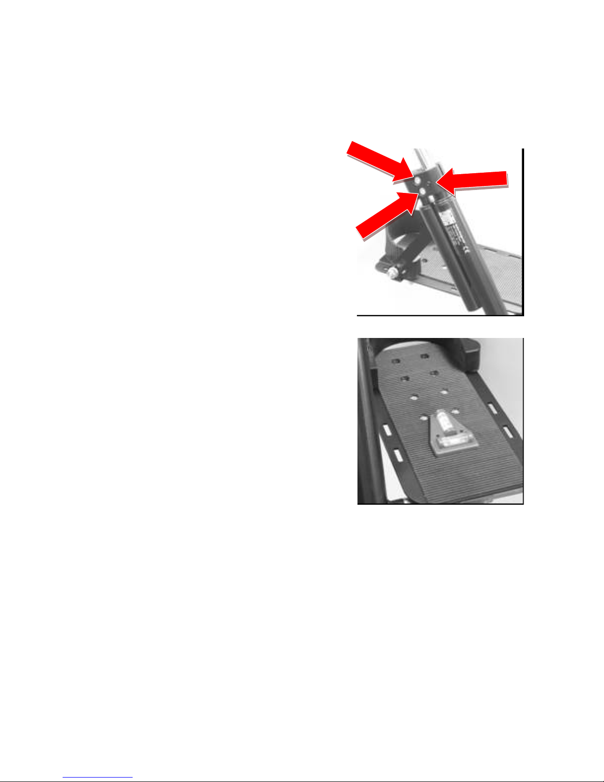
Adjusting the Height of the Dynamic Footrest Assembly
1.
To adjust the height of the footrest,
loosen the grub screw. Loosen the two
retaining bolts until you can slide the
footrest assembly up and down the
footrest drop tube. When you have
reached the required position, tighten
the retaining bolts.
2.
You may want to use a spirit level to
ensure the footplate is level.To adjust
the level, loosen the two retaining bolts
above and rotate the footrest assembly
around the drop tube. Alternatively,
adjust the footplate as shown in X
below.
7
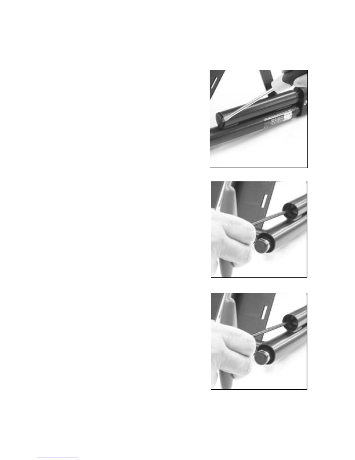
Adjusting the Stiffness of the Dynamic Footrest
The stiffness of the footrest is adjusted by changing the internal spring. Additional springs are
available from Active Design. Four different spring ratings are available.
1.
Ensure the Dynamic Footrest has fully
returned to its ‘rest’ position. Carefully
remove the tube bung using a flat
screwdriver.
2.
Using a 4mm allen key, remove the
spring retaining bolt and washer from
inside the sliding tube.
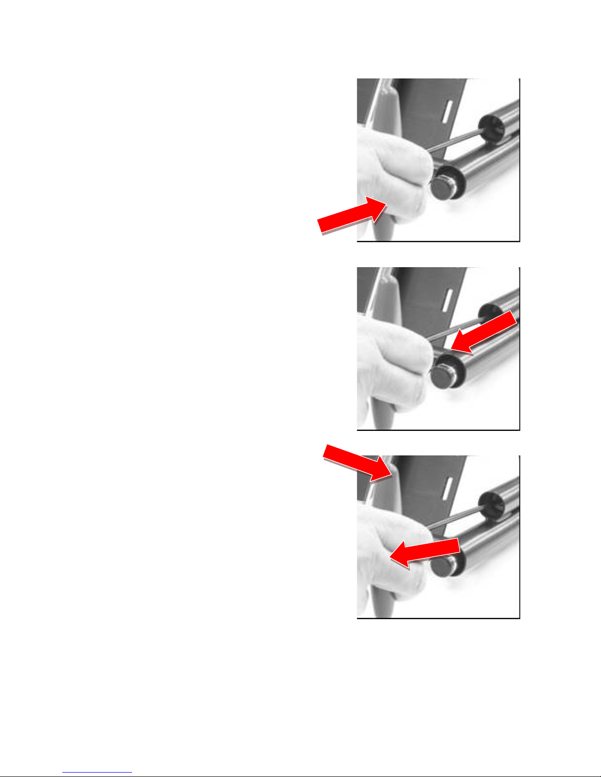
3.
The spring can then be removed. To
reassembly the footrest, insert the
spring you require and replace the
spring retaining bolt and washer while
holding the tube assembly upside
down. Fully tighten the bolt and then
replace the tube bung. Check the
operation of the assembly.
8
Adjusting the Footplate Position
1.
Loosen the bolt attaching the bottom
end of the Footplate Rear Strut.
2.
Loosen the bolt attaching the top end
of the Footplate Rear Strut.
3.
Adjust the width and depth positon of
the footplate by loosening the two nuts
shown. Once the required position has
been reached, tighten the nuts. You
may also wish to check that the
footplates are level.

9
SECTION 4 – FINAL FITTING
Ensure all mounting bolts are tightened, in particular the grub screw in the Height
Adjustment Block.
Check the operation of the Dynamic Footrest Assembly, it should move freely on
the footrest drop tubes and return to its rest position when no force is being
applied to it. Please contact us if required.
SECTION 5 – REVIEW AND MAINTENANCE
We recommend that the red seat restraining strap is fastened around the back of
the remaining seat frame as a secondary safety device, and that the armrests are
also used.
The dynamic footrest should be checked every 8 weeks initially, and then no less
frequently than every 6 months.
If you are unsure about any part of these instructions, please contact us.
Active Design Ltd
68K Wyrley Road
Birmingham B6 7BN
Tel: (0121) 326 7506
Fax: (0121) 327 8807
E-mail:
Web: www.activedesign.co.uk
INS122-1 October 2009
Table of contents
Other Active Design Wheelchair manuals


