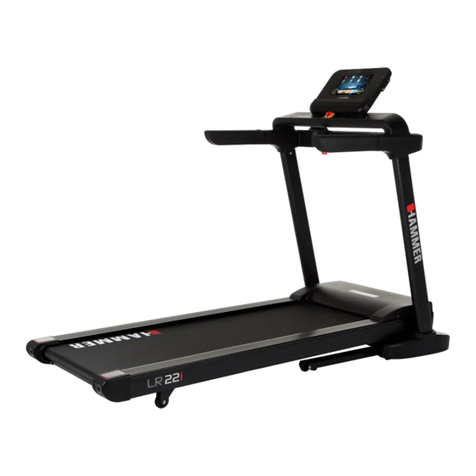
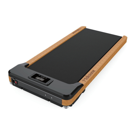
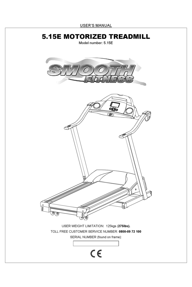
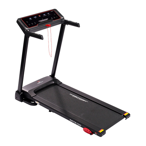
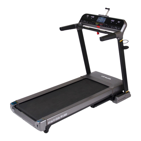
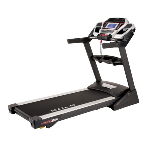
ACTIVE STATION AST1001 User manual

~1~
OWNER'SMANUAL
AST1001/ASWD1001/ASWD2001
IMPORTANT:Readallinstructionscarefullybeforeusingthisproduct.Retainthisowner’smanual
forthefuturereference.

~2~
Caution:Theuseriscautionedthatchangesormodificationsnotexpresslyapprovedbytheparty
responsibleforcompliancecouldvoidtheuser'sauthoritytooperatetheequipment.
ThisdevicecomplieswithPart15oftheFCCRules.Operationissubjecttothefollowingtwoconditions:
(1)thisdevicemaynotcauseharmfulinterference,and(2)thisdevicemustacceptanyinterference
received,includinginterferencethatmaycauseundesiredoperation.
NOTE:ThisequipmenthasbeentestedandfoundtocomplywiththelimitsforaClassBdigitaldevice,
pursuanttoPart15oftheFCCRules.Theselimitsaredesignedtoprovidereasonableprotectionagainst
harmfulinterferenceinaresidentialinstallation.Thisequipmentgenerates,usesandcanradiateradio
frequencyenergyand,ifnotinstalledandusedinaccordancewiththeinstructions,maycauseharmful
interferencetoradiocommunications.However,thereisnoguaranteethatinterferencewillnotoccurin
aparticularinstallation.
Ifthisequipmentdoescauseharmfulinterferencetoradioortelevisionreception,whichcanbe
determinedbyturningtheequipmentoffandon,theuserisencouragedtotrytocorrectthe
interferencebyoneormoreofthefollowingmeasures:
‐‐Reorientorrelocatethereceivingantenna.
‐‐Increasetheseparationbetweentheequipmentandreceiver.
‐‐Connecttheequipmentintoanoutletonacircuitdifferentfromthattowhichthereceiveris
connected.
‐‐Consultthedealeroranexperiencedradio/TVtechnicianforhelp.
FCCRadiationExposureStatement:
ThisequipmentcomplieswithFCCradiationexposurelimitssetforthforanuncontrolledenvironment.
Thistransmittermustnotbeco‐locatedoroperatinginconjunctionwithanyotherantennaor
transmitter.

~3~
IMPORTANTSAFETYPRECAUTIONS
1. Plugthepowercordintoasurgeprotector(notIncluded)thenplug the surge protector into a
groundedcircuit.Nootherappliancesshouldbeonthesamecircuit.
2. Positionthetreadmillonaclearlevelsurface.Donotplacethetreadmillonthickcarpetasitmay
interfere with proper ventilation. Always place treadmill indoors and never place treadmill near
water.
3. Startthetreadmillwhileyouarestandingonthesiderails.Adjustspeedinsmallincrementstoavoid
suddenjumpsinspeed.
4. Alwayswearwalkingoraerobicshoeswithrubbersoles.
5. Alwaysunplugthepowercordbeforeremovingthetreadmillmotorcover.
6. Keepsmallchildrenawayfromthetreadmillduringoperation.
7. Alwaysattachthesafetykeycordtoyourclothingwhenusingthetreadmill.
8. Thepowercordandplugmustalwaysbeinperfectcondition.Otherwise,donotattempttorepair
onyourown. Servicingother thanthe proceduresinthis manual,shouldonlybeperformedbyan
authorizedservicerepresentative.
9. MAXIMUMUSERWEIGHT:300lbs
10. Keepatleast2’ofclearspacearoundthemachineonthesidesandbackoftheuser
Notethefollowingtreadmillelectricalspecifications:
a.Ratedpowerinput:1120W;
b.Powervoltagesupply:110V‐127V;
c.Ratedfrequency:50‐60Hz;
d.Maximumcurrent:15amps.
Introductiontoyourtreadmill:
CongratulationsforchoosingtheActiveStation’sTreadmill.Yourtreadmillcomeswithmanyfeaturesand
benefits. The information below will help youfamiliarize yourself with your treadmill and understand
how to get the most out of the technology in the machine. When callingyourservicerepresentative,
alwaystakenoteoftheserialnumberlocatedonthemotorcovernearthepowercordcable.

~4~
ASSEMBLYINSTRUCTIONS
Ⅰ
Ⅱ
Ⅲ
Ⅳ
Ⅴ
Ⅵ
HARDWARECONTENTS:
Parts# Description Qty.
ⅠMAINFRAME 1
ⅡSAFTYLOCK 1
ⅢOILBOTTLE 1
ⅣCONSOLESET 1
Ⅴ POWERCODE 1
ⅥALLENWRENCH&WRENCHW/SCREWDRIVER 1

~5~
EXPLODEDDIAGRAM
35
35
24
24
28
28
22
62
62
56
88
86
80
79
77
75
76
74
66
65
57
53
53
46
44
44
44
40
39
40
85
29
32
32
32
29
32
32
32
32
32
32
30
29
25
17
17
15
15
23
30
23
30
30
23
12
7
30
25
83
84
71
9
9
51
63
51
27
51
27
1
59
50
44
44
39
11
30
25
25
25
55
6768
70
30
8
30
8
2
64
69
52
89
3
5
4
6
36
37
26
31
41
26
78
73
72
32
62
32
62
32
32
62
32
32
32
33
33
33
33
16
32
44
4444
32
32
32
62
32
10
44
2590
53
53
10
44
3025
3434
81
47
93
92
91
82
45
48
35
35
60
21
19
18
21
21
20
29
25
38
31
2638
38
38
38
38
31
31
31
31
26
26
26
26
21
21
21
19
20
25
18
17
55
32
87
32
62
62
29
85
57
49
50
61
14
14
43
61
49
544213
51
6
58
25
29
26
31
17
17
17
17
17
17

~6~
PARTSLIST
# DESCRIPTION REMARKS QTY # DESCRIPTION REMARKS QTY
1 Mainframe 1 47 Consoletopcover 1
2 Motorholder 1 48 Consolebottomcover 1
3 Oilpipeholder 1 49 Siderail 2
4 Consoleslidingholder 1 50 Rearendcap 1Pair
5 Consolefixedholder 1 51 Footadjuster 4
6 Footadjusterholder 2 52 Stopper 1
7 Bolt M8*35 1 53 Stopper 4
8 Bolt M8*45 2 54 Belt 1
9 Bolt M8*40 2 55 Rearwheel 2
10 Bolt M8*20 2 56 Roller 2
11 Bolt M8*210 2 57 Gelcushion 2
12 Bolt M8*30 1 58 Runningbelt 1
13 Bolt M8*60 2 59 Runningdeck 1
14 Bolt M8*65 3 60 Powercordbuckle 1
15 Bolt M8*20 6 61 Anti‐slipmat 2
16 Bolt M5*30 1 62 R‐shapebuckle 11
17 Bolt M5*10 13 63 Teejunction 1
18 Bolt M8*32 2 64 Oilpipe 1
19 Bolt M8*40 2 65 Oilpipeswitch 1
20 Bolt M6*25 2 66 Powercord 1
21 Bolt M6*30 6 67 Powerswitch 1
22 Bolt M3*10 2 68 Over‐currentprotector 1
23 Springwasher D8 6 69 Powerinput 1
24 Springwasher D5 2 70 Poweroutput 1
25 Nylonnut M8 12 71 DCmotor 1
26 Nylonnut M6 10 72 Ferritebead 4
27 Hexnut 273 Filter 1
28 Nylonnut M4 2 74 Ferritecord 5
29 Lockwasher D8 6 75 Powerconnectingwire 1
30 Flatwasher D8 18 76 Powerconnectingwire 1
31 Flatwasher D6 10 77 Powerconnectingwire 1
32 Screw ST4.2*12 35 78 Powerconnectingwire 1
33 Screw ST4.2*25 4 79 Groundlead 1
34 Screw ST2.5*7 7 80 Groundlead 1
35 Screw ST4.2*15 10 81 Uppercontroller 1
36 Openspanner 182Tableadjuster 1
37 Allenwrench 1 83 Lowercontroller 1
38 Washer 6 84 Lubricator 1
39 Sleeve φ8.5*φ12*80 4 85 Roundcushion φ30*M6*16.5
2
40 Sleeve φ8.5*φ12*25 2 86 Signalline 1
41 Adjusterbolt M6*40 4 87 Speedsensor 1
42 Frontroller 188Sensorholder 1
43 Rearroller 1 89 Switchsensor 1

~7~
# DESCRIPTION REMARKS QTY # DESCRIPTION REMARKS QTY
44 wheelbearing 12 90 Emergencyswitch 1
45 Motortopcover 191Membraneswitch 1
46 Motorbottomcover 192Consoleoverlay 1
93 Membraneswitch 1
ASSEMBLYSTEPS
Step1:Locateacomfortableworksite.Setthetreadmillinaclearareaandremoveallpackaging
materials.Donotdisposeofthepackaginguntilassemblyiscompleted.Refertothedrawingsbelowto
identifythepartsusedinassembly.
Remarks:Bettertoassemblethemachinewithmorethantwopeopletoavoidinjury.
Step2:Attachtheconsoleset(III)tothebottomofthetablewithsupplied4screws(35).
Remarks:Adjustthetensionoftheconsolesetontherailsbythe4piecesofscrewsasthearrowspointin
thebelowpicture.

~8~
Step3:Connectthetreadmillandtablecontrolwiresandplacetheemergencyswitchontotheconsole.
Step4:Turnontheknob(A)forself‐lubricatingcounterclockwiseasshownbelow.

~9~
CAUTION:
1.DONOTPLUGINTHEPOWERCORDUNTILFINALASSEMBLYHASBEENCOMPLETEDANDMOTOR
COVERISINPLACE.
2.Readtheinstructionsfullypriortoassemblystart.
4.KeepChildrenawayfromthetreadmillatalltimes.
DIMENSIONSANDPARAMETERS
SUGGESTEDSTRETCHES
1. WARM‐UP:
Aproperwarm‐upincreasesyourbodytemperature,heartrateand circulation in preparation for
exercise. Starteachworkoutwith5to10minutesofstretching and light exercise. See suggested
stretchesbelow:
BUILTUPSIZE 1,960×710×230mm
77.2×28×9.1inch SPEEDRANGE 0.6–2.5MPH
RUNNINGAREA 1,480×510mm
58.3×20inch
MAXUSER
WEIGHT 136Kg/300Lb
LEDDISPLAY SPEED,DISTANCE,CALORIES&TIME.
CALF
/
ACHILLES
INNERTHIGH
FORWARD
BENDS
SIDEBENDS OUTERTHIGH

T
h
1.
2.
3.
4.
B
U
Pl
e
1.
2.
3.
a.
b.
2.
5
4.
5.
6.
7.
8.
h
eLEDwind
Window
Window
Window
CAL.(cal
o
U
TTONOP
E
e
aseNOTE
START:P
r
STOP:Pr
e
SPEED▲
:
Tosetthe
s
Increase t
5
mph,pres
s
SPEED▼
a.Toset
t
b.Decre
a
0.6mph,
HEIGHT
▲
HEIGHT
▼
HEIGHT
M
Presshei
g
owshows:
MPH(spee
TIME:Disp
l
MILES(dist
o
ries):Disp
l
E
RATIONS:
thatthetr
e
r
essthebu
t
e
ssthebut
t
:
s
peed,pres
s
he speed
a
s
ingSPEED
▲
t
hespeed,
p
a
sethesp
e
pressingSP
▲
:Increase
▼
:Decreas
e
M
EMORY1,
2
g
htmemor
y
C
MPH(spee
d):Display
s
l
aysthetot
a
ance):Disp
l
aysthetot
a
e
admillcan
t
tontostar
t
t
ontostop
t
s
thespeed
a
s desired
▲
willnolo
p
ressthes
p
e
ed as desi
r
EED▼will
n
theheight
e
theheigh
t
2
,3,4:Press
y
buttonfo
C
ONSO
d),TIME,
M
s
thecurre
n
a
lworkout
t
laystheto
t
a
lworkout
c
beoperat
e
t
thetread
m
t
hetreadm
buttonun
t
while wal
k
ngerincre
a
p
eedbutto
n
r
ed while
w
n
olongerd
e
asdesired
b
t
asdesired
buttonswi
r5second
s
~10~
LEOP
E
M
ILES(dista
n
n
tspeed.Sp
t
ime.Time
t
alworkout
c
alories.Ca
e
dON
L
Yw
h
m
ill.
ill.
t
ilthedesir
e
k
ing by pr
e
a
sethespe
e
n
untilthe
d
w
alkingbyp
e
creaseth
e
b
ypressing
bypressin
g
llautomati
c
s
tosethei
g
E
RATIO
N
n
ce)andC
A
eedRange
:
Range:0:0
0
distance.
D
loriesrang
e
h
enthesaf
e
e
dspeeds
h
e
ssing the
S
e
d.
d
esiredspe
e
ressingthe
e
speed.
theHEIGH
T
g
theHEIG
H
c
allytakey
o
g
htmemor
y
N
A
L.(calorie
s
:
0.6~2.5M
P
0
~99:59.
D
istanceran
e
:0~999.
e
tykeyisi
n
h
owonthe
S
peed▲.
W
e
dshowon
Speed▼.
W
T
▲.
H
T▼.
o
utothed
e
y
s
).
P
H.
ge:0.0~99.
n
serted.
display.
W
hen the
s
thedispla
y
W
henthe
s
e
siredheig
h
9.
s
peed reac
h
y
.
s
peed reac
h
h
tlevel.
h
es
h
es

~11~
OPERATIONMODES
1. Normal:InsertthesafetyKeythenpress“START”.Thentherunning beltis starting to move. The
treadmillwillstartfromthespeedof0.6mphandthetimewillcountupfrom0:00to99:59.When
thetimereachesto99:59,itwillcountupfrom0again.PressSPEED▲ and ▼toadjustthespeed.
2. Bluetooth: Download and install the Active Station APP. Pair it with the unit via
Bluetoothandconnectwhenusingittotakeadvantageofitsfeatures.
3. Sleep:ThetreadmillwillturntoSLEEPstatusifinactivefor10minutes.
4. Emergencystop:Theemergencyswitchisdesignedtofunctionasanemergency
stop mechanism. For this reason it extremelyimportant that thesafetykeyCORDisattachedto
your clothing at all times while using the treadmill. Pull out fromtheemergencyswitch,the
treadmill will stop immediately with the beep signaling and the windows will display “‐‐‐“. The
treadmillwillstop.Attachtheswitchtostartthetreadmillagain.
PARAMETERRANGE
SETTINGPARAMETER DISPLAYRANGESETTINGBEGINING
VALUE SETUPRANGE
SPEED 0.6-2.5MPH 0.6MPH(setinapp) 0.6-2.5MPH
TIME(MINUTE:SECOND) 0:00-99:59 0:00(Timerinapp) 5mnsincrements
DISTANCE(MILES) 0.00-99.9 N/A N/A
CALORIES(THERM) 0-999 N/A N/A

~12~
TROUBLESHOOTINGGUIDE
Error
code Cause Checking Correction
E01 Nosensorsignal
1.Checkthedistanceand
placebetweensensorand
magnet.
1.Adjustthedistance
betweenthesensorandthe
magnet.
2.Checkifthewireisbroken. 2.Changethewire.
3.Checkifthemagnetismis
good. 3.Changethemagnet.
4.Checkifthecontrolleris
damaged. 4.Changetoanewcontroller.
E02 Over‐voltageprotectionofthe
motor
1.Checkifthenetwork
voltageisstable.
1.Regulatorisneededto
adjustthevoltage.
2.Checkifthecontrolleris
damaged. 2.Changetoanewcontroller.
E03 Over‐currentprotection
1.Themachineisoverloaded. 1.Verifyuserweightiswithin
allowedparameters
2.Checkifthemotororthe
rollergetsstuckby
something.
2.Taketheforeignmatter
out.
3.Checkrollerlubrication. 3.Lubricatetheroller.
4.Checkifthecontrolleris
damaged. 4.Changetoanewcontroller.
5.Checkifthemotoris
damaged. 5.Changetoanewmotor.
E04 Opencircuit
1.Checkthewiresofthe
motorareconnectedwell.
1.Connectthemotorwires
properly.
2.Checkifthemotoris
open‐circuit. 2.Changetoanewmotor.
3.Checkifthecontrolleris
open‐circuit. 3.Changetoanewcontroller.
E06 Messagefailure
1.Checkiftheconnecting
wiresarepluggedwell. 1.Plugallthewiresproperly.
2.Checkiftheconnecting
wiresarebroken. 2.Changetothenewwires.
3.Checkiftheconsoleis
broken. 3.Changetoa newconsole.
4.Checkifthecontrolleris
damaged. 4.Changetoanewcontroller.
E07 Emergencyswitchoff 1.Checkiftheemergency
switchisattached.
1.Attachedtheemergency
switch.

~13~
Error
code Cause Checking Correction
2.Checkifthesensorwireof
theemergencyswitchis
damaged.
2.Changetothenewsensor
wireoftheemergencyswitch.
3.Checkiftheportofthe
emergencyswitchis
damaged.
3.Changetoanewconsole.
E0C Burstclash Thecontrollerisdamaged. Changetoanewcontroller.
BELTADJUSTMENT
1. Wesuggestthatyou cutoffpowerfor10minutesafteranextendedwalkingperiod
2. Thebeltistoolooseifitslipsduringusewhenyouapplyforwardpressureonit.
3. Ifthebeltistootight,itwouldaffecttheperformanceofmotorandincreasetheabrasionofroller
andbelt.
4. Whenproperlytightened,thebeltcanbeliftedabout2”‐3”from
thedeck.
Centertherunningbelt
1. Placetreadmillonalevelsurfaceandrunatfullspeed.Ifthebelt
driftstotheright,pullouttheswitch,turntherightadjustingbolt
1/4turnclockwise,thenstartrunninguntilcenteringthebelt.
PICTURE‐A
2. Ifthebeltdriftstotheleft,pullouttheswitch,turntheleft
adjustingbolt1/4turnclockwise,thenstartrunninguntilcentering
thebelt.PICTURE‐B
3. Tightenthebeltifloosenedafteraperiodofusebypullingthe
safetyswitchandturningtheleftandrightadjustingbolt1/4turn
clockwise,re‐startthetreadmill.Repeatuntiladequatetightnessis
achievedPICTURE‐C

~14~
BELTANDDECKLUBRICATION
This treadmill is equipped with a pre‐lubricated, low maintenancedecksystemandanautomatic
lubricationpump.Thepumpisdesignedtolubricatethebeltevery200milesofuse.
Theliquidsiliconebottleneedstobere‐filledevery6,000milesofuse.Tore‐fill,removethemotorcover
andunscrewthecaponthepump.Re‐fillusingonlypureliquidsilicone1000cst(seedrawingbelow).
Incaseitisrequired,pressingthe+and–speedbuttonsatthesametimewillalsorunthelubricate
pumpfor10seconds.
Lubricatingoilrefill
1. Removethemotorcoverscrewsandthemotorcover.
2. LoosenthenutAfromthelubricantpump.
3. Fill bottle with pure liquid silicone 1000cst
lubricantandfastenthenut.
4.Reinstallthemotorcoverandtightenscrews.
This manual suits for next models
2
Table of contents

