Active 25/B User manual

MANUALE D’ISTRUZIONE
MANUEL D’INSTRUCTION
F
IGB OWNER’S MANUAL
GEBRAUCHSANWEISUNG BRUKSANVISNING
NL
S
MANUAL DE INSTRUÇÕES MANUAL DE INSTRUCCIONES
NAVODILO ZA UPORABO
SLO
E
D
P
L / B / EVOLUTION
L / B / BT / EVOLUTION
INSTRUCTIEHANDLEIDING

FIG.2 FIG.3 FIG.4
FIG.6 FIG.7 FIG.8
FIG.12 FIG.13 FIG.14
FIG.9 FIG.10 FIG.11

FIG.15 FIG.16 FIG.17
FIG.18 FIG.19 FIG.20
FIG.21 FIG.24 FIG.25
FIG.26
FIG.27 FIG.28

I
Caro cliente, la ringraziamo vivamente per aver scelto un prodotto di qualità della dittaACTIVE.
Per un corretto impiego del decespugliatore e per evitare incidenti, non iniziate il lavoro senza aver letto questo manuale con attenzio-
ne. Troverete su questo manuale le spiegazioni di funzionamento dei vari componenti e le istruzioni per i necessari controlli e per la
manutenzione.
N.B. : La casa produttrice si riserva la possibilità di apportare eventuali modifiche in qualsiasi momento e senza preavviso.
(INDICE PAG.6)
INTRODUZIONE
F
GB INTRODUCTION
Dear customer, thank you very much for having chosen a quality product of the company ACTIVE.
For proper use of brush-saws and to avoid accidents, do not start work without having read the manual carefully.You’ll find this guide
on the explanations of operation of various components and instructions for the necessary inspections and maintenance.
N.B. : The manufacturer reserves the right to make changes at any time without notice.
(CONTENTS PAG.14)
Cher client, je vous remercie beaucoup d’avoir choisi un produit de qualité de la société active.
Pour un bon usage de la brosse-scies et pour éviter les accidents, il ne faut pas commencer à travailler sans avoir lu le manuel
attentivement. Vous trouverez ce guide sur les explications du fonctionnement de divers composants et des instructions pour les
inspections nécessaires et de l’entretien.
N.B. : Le fabricant se réserve le droit d’apporter des changements à tout moment sans préavis.
(INDEX PAG. 22)
INTRODUCTION
FIG.31 FIG.32 FIG.33
FIG.29
B
FIG.30

D
Geehrter Kunde, wir danken Ihnen, dass Sie ein Qualitätsprodukt der FirmaACTIVE gewählt haben.
Zur korrekten Verwendung der Heckenschere und zur Vermeidung von Unfällen muss vor dem Beginn der Arbeiten diese
Gebrauchsanweisung aufmerksam durchgelesen werden. In dieser Gebrauchsanweisung finden Sie die Erklärungen für den Betrieb
der verschiedenen Bauteile und dieAnweisungen für die erforderlichen Kontrollen und Wartungsarbeiten.
ANMERKUNG:Der Herstellerbehält sichdasRechvor, jederzeitund ohneVorankündigungenirgendwelcheÄnderungenvorzunehmen.
(INHALTSVERZEICHNIS S.38)
EINLEITUNG
S
Bäste Kund, tack för att Du har valt en kvalitetsprodukt från företagetACTIVE.
För att kunna använda busktrimmern på ett korrekt sätt och förhindra olyckor är det viktigt att den inte tas i bruk förrän du noggrant har
läst igenom denna handbok. I handboken finns förklaringar till de olika komponenternas funktioner och instruktionerna för de
nödvändiga kontrollerna och för underhållet.
OBS! Tillverkaren förbehåller sig rätten att göra ändringar på produkten utan att från gång till gång anpassa innehållet i handboken.
(INNEHÅLLSFÖRTECKNINGSIDA. 47)
INLEDNING
Caro cliente, agradecemo-lhe muito ter escolhido um produto de qualidade da firmaACTIVE.
Para um uso correcto do cortador de mato e para evitar acidentes, não comece o trabalho sem ter lido este manual com atenção.
Neste manual vai encontrar as explicações do funcionamento dos vários componentes e as instruções para os controlos
necessários e para a manutenção.
N.B. : o fabricante reserva-se a possibilidade de aportar eventuais modificações em qualquer momento e sem pré-aviso.
(ÍNDICE PÁG.55)
INTRODUÇÃO
EINTRODUCCIÓN
Estimado cliente, muchas gracias por haber elegido un producto de calidad de la empresa en cuestión.
Para un buen uso de la brocha-y las sierras para evitar accidentes, no debemos empezar a trabajar sin haber leído el manual
cuidadosamente. Va a encontrar esta guía en las explicaciones de cómo los diversos componentes y las instrucciones para el
mantenimiento y las inspecciones necesarias.
N.B : El fabricante se reserva el derecho a realizar cambios en cualquier momento sin previo aviso.
(ÍNDICE. PAG. 63)
SLO UVOD
Spoštovani kupec, zahvaljujemo se vam za nakup kakovostnega izdelkaACTIVE.
Za pravilno uporabo motorna kosa in za preprecevanje nesrec ne zacnite z delom ne da bi natancno prebrali ta navodila. V teh
navodilih je obrazlo•itev delovanja sestavnih delov in navodila za potrebne preglede in vzdr•evanje.
N.B.: Podjetje si pridr•i pravico glede mo•nih sprememb navodil kadarkoli in brez predhodnega obvestila.
(VSEBINAPAG. 71)
NL
Geachte klant, hartelijk dank voor het kiezen van een kwalitatief product van de onderneming actief is.
Voorhet juistegebruikvan penseel schommelsen ter voorkomingvan ongevallen, nietbeginnen te werkenzonderde gebruiksaanwijzing
aandachtig door te lezen. U vindt deze gids over de uitleg van de werking van diverse onderdelen en instructies voor de noodzakelijke
inspecties en onderhoud.
N.B. : De fabrikant behoudt zich het recht voor om op elk moment zonder voorafgaande kennisgeving.
(INDEX PAG. 30)
INLEIDING

IITALIANO
6
INDICE
1.Spiegazionesimboli.......................................................................................................................................................................................Pag. 5
2.Perla vostrasicurezza............................................................................................................................................................................................5
3.Descrizionedelle parti............................................................................................................................................................................................6
4.Datitecnici eDichiarazione diconformità..........................................................................................................................................................7
5.Caratteristichedel motore.....................................................................................................................................................................................8
6.Assemblaggio.........................................................................................................................................................................................................8
7.SistemaRotofix.......................................................................................................................................................................................................9
8.Oliomotore..............................................................................................................................................................................................................9
9.Modalitàdi utilizzo.................................................................................................................................................................................................9
10.Preparazioneall’uso...........................................................................................................................................................................................10
11.Manutenzioneperiodica....................................................................................................................................................................................11
12.Pianodimanutenzioneprogrammata delmotore...........................................................................................................................................11
13.Rimesaggio..........................................................................................................................................................................................................11
14.Certificatodi garanzia........................................................................................................................................................................................12
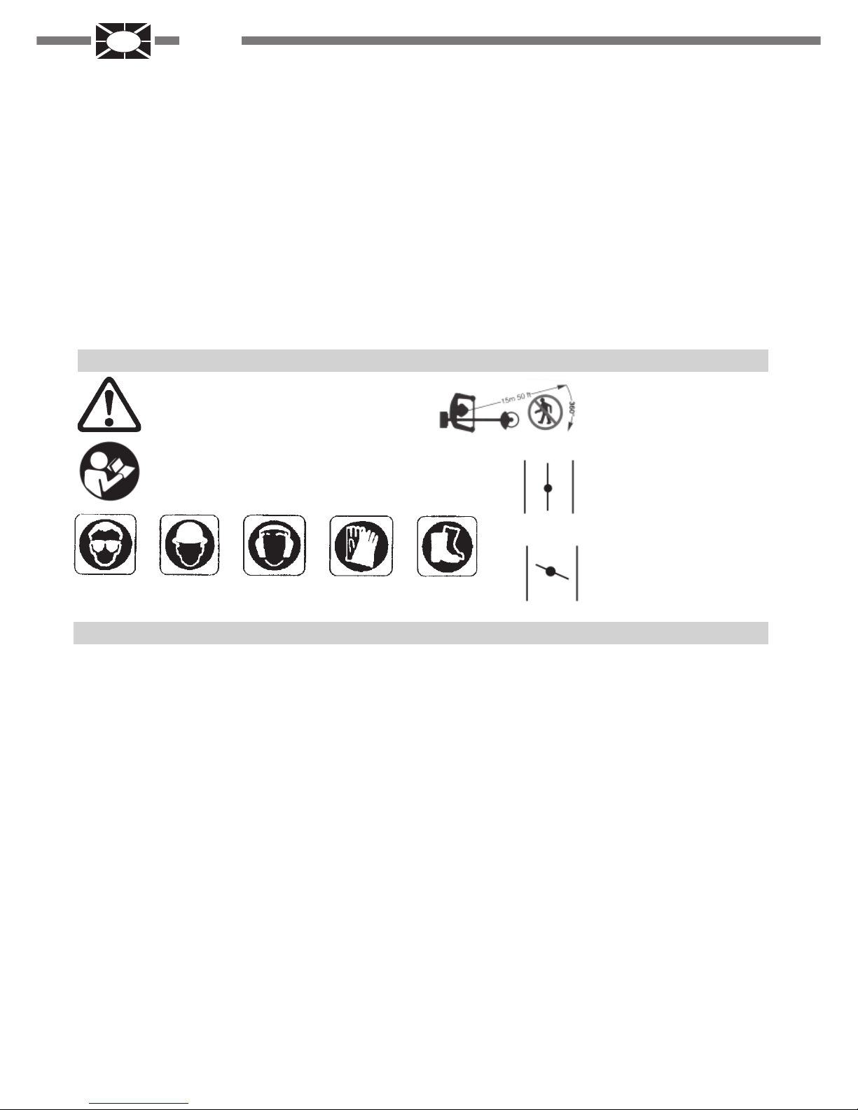
1.SPIEGAZIONESIMBOLI
Avvertenza,pericoloed attenzione.
Leggereil manuale diuso emanutenzione
prima di utilizzare questa macchina.
Indossaredispositivi diprotezione duranteil funzionamento
di questa macchina.
2.PERLAVOSTRASICUREZZA
12-Accertarsiche la protezionedel discoo dellatestina egli
altridispositivi siano montaticorrettamente e saldamente.
13-Trasportareil decespugliatore amotore fermoe con il
1-Leggere attentamente queste istruzioni ed accertarsi di
comprenderleprimadi farfunzionareI’unità.Attenersia tutte
leavvertenzeedalle istruzionidisicurezza.Conservare que-
stomanuale a titolo difuturo riferimento.
2-Usare solamente ricambi originali, pezzi di ricambio pro-
dottida altrifabbricanti potrebberoadattarsi male ecausare
lesioni .
3-
Indossareabiti adattiedarticoli disicurezza quali
:stivali, panta-
lonirobusti, guanti,visierao occhialiprotettivi, cuffiae casco
protettivo.
4-Nonindossarearticolid'abbigliamentopocoaderentioslac-
ciati.
5-Nonpermettere ad altrepersone, bambini oanimali di re-
starenel raggio di 15m. durante I’usodel decespugliatore.
6-Non operare con il decespugliatore quando si è stanchi,
malati o sotto I’effetto di alcool, droghe o farmaci.
7-Nonpermettere airagazzi di usareun decespugliatore.
8-Mantenersiben saldiedin equilibrio.Mantenere ildisposi-
tivo di taglio al di sotto dell’altezza della cintura.
9-Usareildecespugliatore solamentepercompiti indicatidal
presentemanuale.
10-Ispezionarela macchina primadi ogni impiego.Control-
lareche la levaacceleratore funzioni bene.Accertarsicheil
discosia liberodi giraree non siaa contattocon corpiestra-
nei, che non ci siano perdite di carburante, che i dispositivi
di sicurezza non siano allentati ecc..Sostituire le parti dan-
neggiate.
11-Avviare il decespugliatore solo in luoghi ben ventilati, i
gas di scarico, se respirati, possono causare una asfissia
mortale.
copri disco montato.
14-Usareesclusivamente il filodi nylono ildisco raccoman-
dato dal fabbricante, per esempio non usare in alcun modo
fili di metallo o corde rinforzate in metallo, visto che potreb-
berorompersi eformare proiettili pericolosi.
15-Con il motore in moto non fare alcuna manutenzione e
non toccare il disco.
16-Unavolta spentoil motore, primadi appoggiareper terra
l‘unità accertarsi che il dispositivo di taglio si sia arrestato.
17-Arrestareilmotoree lasciarloraffreddareprimadelriforni-
mento.Riempire il serbatoiolontano dafonti di caloree non
fumare durante il rifornimento o la miscelazione del carbu-
rante.
18-Non togliere il tappo del serbatoio con il motore in moto.
19-Asciugare il carburante eventualmente rovesciato sulla
macchina. Spostare il decespugliatore di 3 metri dal punto
di rifornimento prima di mettere in moto il motore.
20-Nonusare carburanteper operazioni dipulizia.
21-Noncontrollare lascintilladella candelavicino alforodel-
lacandela.
22-Nonlavorare conunamarmitta danneggiata.
23-Primadell ‘usodel decespugliatore, liberareI’area dato-
sareda tutti glioggetti: quali sassi, pezzidi vetro, filometal-
lico o corda ecc.,che possono venire scagliati o impigliarsi
neldispositivo di taglio.
24-Prima diriporrein magazzinoil decespugliatore,lasciare
raffreddareil motoree svuotareil serbatoiodi carburante.
Tenere lepersone lontane15 mt.
Farfallaariaaperta,
funzionamento
Farfallaaria chiusa,

I
ITALIANO
7
3.DESCRIZIONEDELLE PARTI
25-Riporre ildecespugliatorein mododa prevenirele lesioni
accidentali causate da oggetti taglienti, lontano da fonti di
caloree sollevato dalsuolo.
26-Nonavviareilmotoresenzail braccio (trasmissione)mon-
tato.
27-Assicurarsi che il dispositivo di taglio sia stato instal-
lato correttamente e che sia ben stretto.
28-Sostituirela testina oil discose apparisseroincrinati,
scheggiatio danneggiati inqualsiasi modo.
29-Indossare iguanti permaneggiare oeffettuare lama-
nutenzionedella lama.
30-Con il motore al minimo il disco non deve girare. In
casocontrario regolare lavite del minimo.
31-Trasportareil decespugliatoreamotore fermoe conil
copri disco montato.
33-Usare sempre le lame affilate,una lama senza filo ha
mag-gior probabilità di bloccarsie causare contraccolpi.
Sostituirei dischi cheabbiano perso ilfilo. NON CERCA-
REdi affilarli.
34-E’necessario arrestareil motoreed esaminareildisco
tutte le volte che si colpisce un oggetto duro.
35-Gliattrezzi dataglio oppuregli accessoriusati dovran-
noessere originaliACTIVEoppureessere espressamen-
teapprovati perI' applicazioneal presente modello.
36-Quando viene applicato il disco per il taglio del legno,
montare la protezione disco specifica .
32-Ondeevitareil rischiodilesioni,spegnere sempreilmoto-
re prima di rimuovere qualsiasi oggetto avvolto sia attorno
all’albero della testina o al disco.
1.Interruttore diarresto (STOP)
2.Levaacceleratore
3.Semi acceleratore
4.Levettafarfallaaria(STARTER)
5.Primer (spurgodel carburatore)
6.Tapposerbatoiocarburante
7.Serbatoio carburante
8.Impugnaturaavviamentomotore
9. Filtro aria
10.Impugnaturaanteriore
11.Attacco cinghiaggio
12.Tubo di trasmissione
13.Giuntomotore/asta (ANTIVIBRANTE)
14. Protezione di sicurezza
15.Tubo
16. Coppia conica
17. Disco
18. Testina a fili di nylon
Solo per modelli EVOLUTION:
19.Albero di trasmissione
20.Giunto accoppiamento accessori
21. Levafissaggio ditrasmissione
ACCESSORIARICHIESTA:
A.Potatoreangolato35°
B.Tagliasiepi
C.Potatore dritto

IITALIANO
8
4.DATITECNICI E DICHIARAZIONE DICONFORMITA’
ACTIVE s.r.l. Zona Artigianale - 26037 S. Giovanni in Croce (CR)
dichiara sotto la propria responsabilità che la macchina:
25 / B
IMPUGNATURAMANUBRIO MANUBRIO IMPUGNATURA
24.5
0.81 /1.1 (7000 rpm)
33.5
1.18 / 1.6 (7000 rpm)
AMEMBRANA WALBRO WYL
DIGITALE
DISPOSITIVODISICUREZZACONSGANCIOAUTOMATICO
26mm.
1 : 1.57
MODELLO: PRESSIONEACUSTICA
LpA av - EN ISO 22868 POTENZAACUSTICA
LwA av - EN ISO 22868
24.5 / 33.5 cm³ 78.7 / 82.2 dB (A)
87.7 / 91.2 dB (A)
90.7 / 96.6 dB (A)
97.7 / 103.6 dB (A)
25 / EVO 35 / L 35 / EVO
0.65 L
0.5 L
0.1 L (100 cc.)
0.08 L (80 cc.)
OLIOMOTORESAE10W-30 SF OSUPERIORE
centrifuga da 54 mm centrifuga da 78 mm
tra motore e trasmissione
5.8 kg 6.5 kg 7.2 kg6.5 kg6.70 kg 7.40 kg
VIBRAZIONI
ENISO22867
25 B-EVO 25 / L 35 B-BT-EVO 35 / L
Manico dx
(posteriore)
Manico sin
(posteriore)
Min m/s2
Min m/s2
Max m/s2
Max m/s2
4.72
4.7
3.83
7.56
2.59
6.27
3.26
7.24
2.79
2.27
3.06
2.19
2.34
9.53
3.83
10.74
MODELLO:
ALBERTOGRIFFINI
PRESIDENTE
ACTIVE S.r.l.
Via Delmoncello, 12
26037 San Giovanni in Croce (CR) - ITALY
10/10/2008
è conforme alle prescrizioni della direttiva 2006/42/CE, 89/336/CE, 2004/108/CE, 2000/14/CE, 2002/44/CE
Ladeterminazionedel livello di potenza sonoro,Misuratae Garantita, è stataeseguitain base
alla direttiva 2004/14/CE, allegato V,in applicazione alla norma ENISO 22868
25 / L 35 / B 35 / BT
7.0 kg
MODELLO ACTIVE
CILINDRATAcm³
POTENZA Kw /CV
CARBURATORE
ACCENSIONE
CAPACITA' SERB. CARB.
FRIZIONE
SISTEMA ANTIVIBRAZIONE
MANUBRIO/IMPUGNATURA
ACCELERATORE
TUBOTRASMISSIONEØ
RAPPORTOCOPPIACONICA
PESOKg.
LUBRIFICANTE
CAPACITA'SERB.OLIO

I
ITALIANO
9
6.ASSEMBLAGGIO
-Assicurarsiche laflangia superiore(5) siaposizionatacor-
rettamente. Montare la lama assicurarsi che sia centrata
sulla flangia (5). Assicurarsi del giusto senso di rotazione
(scritteofreccia didirezionerivolte versol'alto conmacchina
inposizione dilavoro).
-Montare laflangia inferiore (3),coppetta di protezione(2) -
(sela flangiainferiore èsprovvistadi protezioneper ildado),
avvitareil dado (1)in senso antiorarioa Kgm 3.0 (30Nm).
- Per bloccare il dado (1), girare la lama sino a che il foro
della flangia superiore corrisponda con il foro della coppia
conica, ed inserire la chiave a brugola in dotazione (4mm),
Fig. 18
- Montare la testina a fili di nylon seguendo la disposizione
illustrata: Flangia superiore, testina a fili di nylon. Fig. 19
Serratea mano in senso antiorario come illustrato
nella Fig. 20 dopo aver inserito la chiave a brugola (4
mm) nel foro 3 della coppia conica.
Per la vostra sicurezza utilizzare lame originali
ACCESORIARICHIESTA(Mod. EVO).
A-POTATOREANGOLATO35°
B-TAGLIASIEPI
C-POTATOREDRITTO
MONTAGGIODEGLIACCESSORIO(A-B-C)SULLAMAC-
CHINAFig.27
-Allentare,insenso antiorario, laleva (1)
- Infilare il tubo (2), fino al riferimento (3) circa 40mm, nel
manicotto(4)tenendo ilpiolino (12)spostato versol'alto,per
facilitare l’inserimento dell’albero (5) nel mozzo dell’albero
(6), ruotare l’attrezzo un poco a destra e un poco a sinistra
fino a che l’attrezzo/tubo sia inserito correttamente.
-Ruotare l’attrezzo nellaposizione di lavoroe bloccarlo tra-
mitela leva (1).Per la sicurezzadell'operatore il tubo 2pre-
sentaun foro13 dove deveinserirsi ilpiolino (12).
MONTAGGIO DELLA PROLUNGA (a richiesta e SOLO
PER GLIATTREZZIA- B - C)
Accopiamento prolunga - macchina fig.28:
-Allentare,in sensoantiorario, la leva(1).
-Infilare iltubo (2)della prolungafino alriferimento (3),circa
40mm., nel manicotto (4) tenendo il piolino (12) spostato
versol'alto.Per lasicurezza dell'operatoreiltubo (2)presen-
taun foro(13) dove deveinserirsi ilpiolino (12).
Accopiamento accessorio - prolunga fig.28:
-Allentare,insenso antiorario, laleva (7)
-Infilareil tubo(8)dell’accessorio finoalriferimento (9),circa
40mm., nel manicotto (10) tenendo il piolino (12) spostato
versol'alto.Per lasicurezza dell'operatoreiltubo (8)presen-
taun foro(13) dove deveinserirsi ilpiolino (12).
ATTENZIONE: per l’utilizzo degli accessori
A - B - C vedi il manuale d’istruzione specifico
allegato ad ogni accessorio.
L’estensione della macchina (solo con gli accessoriA-
B e D) non può superare i 1500mm., altrimenti è peri-
coloso. Si può utilizzare una sola prolunga, la 750mm
o la 1500mm.
MONTAGGIO MOTORE TRASMISSIONE Fig.2
- Assemblare il motore (B) alla trasmissione (A) e fissarlo
tramite le 4 viti (C).
Accertarsi che l'albero e il tubo della trasmissione
siano inseriti correttamente.
MONTAGGIO FILO ACCELERATORE ECAVIELETTRICI
Fig. 3
-Introdurreil cavoacceleratore(A) attraversoiltenditore (B).
Assicurarsiche laguaina(C) delcavo appoggicontro l'inter-
nodel tenditore (B).Accertarsiche laleva acceleratore non
sia bloccata in semi accelerazione quindi agganciare il ter-
minale del cavo nel morsetto (E). Regolare la tensione del
cavo (A) allentando il controdado (D) e girando il tenditore
(B),raggiungendo lagiustatensione, stringereil controdado
(D).Sela regolazioneécorretta, lalevaacceleratoreavrà un
giocolibero dicirca 2mm. primache simuova laleva carbu-
ratore(E).
- collegare i cavi elettrici (F - G)
MONTAGGIO IMPUGNATURA(L) / MANUBRIO (B) - (BT)
Fig.31(TipoL)-Togliereleviti (1)edallargare l’impugnatura
(2)per infilarlanel tubo(3) efissarla tramite leviti (1)e idadi
(4). Posizionare la barriera di sicurezza (5) nell’apposito
alloggiamentoe fissarla tramitela vite (6) edado (7).
Laposizione dell'impugnatura èregistrabile secondole esi-
genzedell'operatore.
Fig.32 (Tipo B) - Posizionare i due mezzi manubri (1 e 2)
nelsupporto (D),assicurarsi chei terminalisiano posiziona-
ti nella gola (4) (vedi freccia), e fissarli tramite il coperchio
(5), le viti (6) e i dadi (7).
Fig.33(Tipo BT) -Smontarelaleva(1).Aprireil supporto(4)
emontare i duemezzi manubri (2-3) nel supportoinferiore.
Assicurarsi che i terminali dei due mezzi manubri siano po-
sizionati nella gola al centro del supporto i quali vengono
fissati tramite il coperchio (4) e la leva (1).
I due mezzi manubri possono essere registrati indipenden-
tementel’uno dall’altro,secondo leesigenze dell’operatore,
allentandola leva(1).
MONTAGGIO PROTEZIONE DISICUREZZAFig.29
Fissareil cavallotto(6) sulla coppiaconica (5) tramitela vite
(1).Applicarela protezione(8) sul tubodi trasmissione(4) e
fissarla tramite il cavallotto (6), la vite (2) la rondella (3) e il
dado(7).
IMPORTANTE:Assicurarsi che il cavallotto (6) sia
fissato sulla coppia conica (5) tramite la rondella e la
vite (1). Per ragioni di sicurezza le lame a sega non si pos-
sonoutilizzare con laprotezione in dotazione.Non cambia-
re la posizione dell'attrezzo di taglio.
MONTAGGIO LAMA E TESTA A FILI Dl NYLON Fig. 17-
18-19-20
-Fig.17Svitareinsensoorarioildado (1);toglierelacoppetta
(2)-se laflangia(3) èsprovvista diprotezioneper ildado-, e
laflangia (3).
Montare la lama (4) seguendo la disposizione illustrata in
fig.18:
5.CARATTERISTICHEDELMOTORE
Il decespugliatore è equipaggiato con un piccolo e leggero
motore a 4 tempi; presenta le seguenti caratteristiche:
1)Un sistemadi lubrificazionedi piccole dimensioniche ga-
rantisceuna grande regolaritàdi funzionamento e checon-
sente al motore di operare in tutte le posizioni.
2)Costruzione compatta grazieall'ottimo design.
4) Robustezza e leggerezza costruttiva grazie ai materiali
plasticicon cui sonocostruiti la copertura delmotore e altre
parti.
5)Leggerezza costruttiva delsistema diguida valvole.

IITALIANO
10
8.OLIOMOTORE
Disporreorizzontalmenteil motore,svitareiltappo (vedifigu-
ra8) e riempire d'olioil serbatoio dalforo filettato.
Illivello dell'oliodeve essere quelloindicato infigura 10.
La capacità del serbatoio è approssimativamente di 0.08L/
0.1L a seconda del modello di motore.
Siraccomanda l'utilizzodi olio tipoSAE 10W-30 SF o supe-
riore.L'utilizzodi olioMulti-gradotendea incrementareicon-
sumi alle alte temperature. Non aggiungete olio con ca-
ratteristiche diverse da quelle dell'olio già esistente nel
motore.
Quandoilserbatoio risultaessere pieno,serrareil tappodel-
l'olio.
La lubrificazione del vostro motore risulta essere vitale per
garantire le prestazioni e la durata nel tempo della vostra
macchina.
goleprescritte dal costruttore in termini dimanutenzione
periodica.
E' bene controllare giornalmente, prima di utiliz
zare la macchina, il livello dell'olio.
Illivellodell'olio deveessere compresofra iriferimenti MINe
MAXsull'asta di controllo.
Per la sostituzione dell'olio esausto (vedi figura 9), basterà
svitareiltappo einclinareil motoredalla partedelforo facen-
do fuoriuscire il lubrificante in un contenitore posto sotto.
Con motore caldo, agite con molta cautela: pericolo
di ustioni.
L'olio esausto deve essere smaltito negli appositi centri di
raccolta in quanto contiene sostanze pericolose per l'am-
biente
9.MODALITA'DIUTILIZZO
Ilmotore èdotato di unsistema dilubrificazione internapar-
ticolarmente ricercato che garantisce un funzionamento
ottimale in tutte le condizioni di utilizzo. Adifferenza di un
normale motore a 4 tempi che è costretto a lavorare solo
orizzontalmente, il motore ACTIVE è stato progettato per
lavorareinqualsiasiinclinazione garantendounaelevata du-
ratanel tempo.
Nelcaso in cuisi impieghi ildecespugliatore in posi-
zione verticale con il motore verso il basso e l'organo
di taglio verso l'alto è bene non superare i due minuti
di utilizzo continuativo. Per ogni altra inclinazione non
sussistonoproblemi di lubrificazione.
Si consiglia per tanto di attenersi scrupolosamente alle re-
NO ! SI !
7.SISTEMAROTOFIX
IMPUGNATURAGIREVOLE
Tirare la ghiera (1) verso l’impugnatura (2) e ruotarla nella
direzionedella freccia.
Inquesto casol’impugnatura rimane inposizione girevole e
l’operatorepuò variarela direzione di taglio.
IMPUGNATURAFISSA
Ruotare la ghiera fino a quando gli innesti si posizionano
nella propria sede. La ghiera scatta e va a bloccare l’impu-
gnatura nella posizione prescelta dall’operatore. In questo
casol’impugnatura rimane inposizione fissa.

I
ITALIANO
11
10.PREPARAZIONEALL'USO
OPERAZIONIPRELIMINARI
Regolazione del cinghiaggio (fig.25) e della posizione del
decespugliatore. Indossare il cinghiaggio, agganciare il
decespugliatoreal cinghiaggiotramite ilgancio (1). Posizio-
nare la fibbia per ottenere la corretta altezza del
decespugliatore.Regolarela staffa(3) inmodoche ildisco o
la testina penda a circa 5 cm. dal suolo.
CARBURANTE
ATTENZIONE il decespugliatoreèequipaggiatodaun moto-
rea 4tempi, quindisi deve utilizzareesclusivamente carbu-
rantecon numero diottani non inferiore a90.
Nonfumare edeseguire ilrifornimento carburantesempre a
motorespento e lontanoda fiamme.
RIFORNIMENTO
ATTENZIONE ll rifornimentodeveessereeffettuatoamotore
spento.Svitare lentamenteil tappo delserbatoio per lascia-
refuoriuscire I’eventualeeccesso dipressione.
Dopoilrifornimento serrarecorrettamenteil tappodelserba-
toio.Spostare ildecespugliatore di almeno3 m.dal punto di
rifornimento prima di mettere in moto il motore. Prima del
rifornimentopulireaccuratamente intornoaltappodel serba-
toio.La sporcizia all’internodel serbatoio causaproblemi di
funzionamentoal motore.
AVVIAMENTO
Appoggiareil decespugliatore sudi una superficie piana
e sgombra e verificare che I’attrezzo di taglio sia libe-
ro di girare.
PortareI’interruttore sulla posizione(1) Fig. 30.
Premere il bulbo (C) 5 o 6 volte Fig. 6.
Tirarela levaacceleratore (2) ebloccarla insemi accele-
razione premendo il pulsante (3), rilasciare la leva (2)
Fig.30.
Portare la leva starter (A) in posizione (B) Fig.12.
Tenendofermoil decespugliatoretirarel‘avviamentoed ai
primi scoppi del motore riportare la leva starter (A) nella
posizioneoriginale aperta(C) Fig.12.
Ripetere la manovra d'avviamento finché il motore non
parte. Amotore avviato, premere I’acceleratore (2) per
sbloccarlodalla posizione disemiaccelerazione e porta-
re il motore al minimo. Fig. 30.
ATTENZIONE:quandoil motoreègiàcaldo,non premere
il bulbo (C) Fig. 6, non usare lo starter per I’avviamento.
Non rilasciare la corda d’avviamento, ciò potrebbe dan-
neggiareilgruppoavviamento.
ATTENZIONE: Primadi usareil decespugliatoreleggere at-
tentamente le norme di sicurezza.
Siraccomanda diusareil decespugliatoredalla partedestra
del corpo (Fig.26), si dà così la possibilità ai gas di scarico
diuscire liberamentesenza venirostruiti dagli abitidell’ope-
ratore. Se siete nuovi all’uso del decespugliatore seguite il
primoperiodo diaddestramento. Ispezionaresempre atten-
tamente la macchina prima dell’uso. Verificare che non vi
sianovitiallentate, partidanneggiatee perditedi carburante.
Controllate periodicamente le condizioni del sistema
antivibrante.Evitate un uso del decespugliatore eccessi-
vamente prolungato, le vibrazioni possono essere dan-
nose. Primadi ogniutilizzo rimuovete dall‘areainteressata:
pietre, vetri, funi, parti metalliche e tutti i corpi estranei che
potrebberoaggrovigliarsisulle partirotantioessere proiettati
pericolosamente a distanza. Indossare il cinghiaggio e ag-
ganciareildecespugliatore.Teneresempreentrambelemani
sulle impugnature durante il funzionamento del
decespugliatore Fig. 26. Utilizzare il decespugliatore come
illustrato nella Fig. 16. Per facilitare l‘operazione di taglio e
per ragioni di sicurezza, posizionare sempre il fermo della
protezionecontro il materialeda tagliare.Verificare sempre
che il disco non subisca incrinature dopo urti accidentali
contro oggetti estranei. Sostituire gli accessori ( dischi,
testineafilo ,protezioni,cinghiaggi) eventualmentedanneg-
giatio eccessivamente usurati.
Fig. 21 Testina a fili di NYLON ACTIVE®. Il dispositivo
ACTIVE consente il caricamento del filo senza smontare la
testina(è unbrevettoACTIVE).
- Usare sempre lo stesso diametro del filo originale per non
sovraccaricareil motore.
-Spegnere ilmotore. Indossare iguanti dilavoro.
Ruotare,insenso orario,ilpomolo (1)finoa chelafreccia (2)
del pomolo sia allineata con una delle boccole (6).
-Inserire il tubo (4)in dotazione attraverso latestina.
- Infilare il filo e togliere il tubo.
Congiungere le estremità del filo e tirare il filo in modo di
avere i due rami del filo della stessa lunghezza.
- Ruotare il pomolo in senso orario, avendo cura di tendere
idue rami del filo ogni3 giri,finoal completoavvolgimento.
SMONTAGGIODELLATESTINA
Premere il pomolo (1). Contemporaneamente premere la
linguetta(5)edestrarreparzialmenteilcoperchio(7)dalcorpo
della testina .Mantenendo il pomolo premuto, premere
l’altralinguetta edestrarre il coperchio.
ASSEMBLAGGIODELLATESTINA
Montare le boccole (6) nella loro sede del coperchio (7).
Montareil rocchettonelcoperchio(7).Posizionarela molla
sulrocchetto oppure all’interno delcorpo della testina.
Montareilcoperchio/rocchetto/boccolenelcorpodellatestina
assicurandosi che le linguette (5) siano nella loro sede.
FUNZIONAMENTO
Perallungareilfilo: fargirarelatestinamantenendoilmotore
accelerato.Battere al suolo il pomolo (1). Ogni scatto corri-
sponde a circa 3 cm. di fuoriuscita del filo.
Nota: non battere la testina su superfici dure può essere
pericoloso.

IITALIANO
12
11. MANUTENZIONE PERIODICA
12.PIANO DI MANUTENZIONE PROGRAMMATADELMOTORE
Sostituirele lame danneggiate, usurate, criccatee non pia-
ne.Verificare sempreil correttomontaggiodella testina afili
di nylon o la lama e che la vite che blocca la lama sia ben
serrata.
FILTRO ARIA (Fig. 14 per 25cc, fig 15 per 35 cc)
-Verificareperiodicamenteilfiltrod'ariain funzionedellecon-
dizionidilavoro
-Toglierela vite(3);
-Togliere ilcoperchio (1);
-Togliere il filtro(2);
- Pulire il filtro (2) con miscela di benzina/olio e strizzatelo;
- Controllare le parti: se necessario sostituirle. Montare in
sensoinverso allosmontaggio.
- Per ottenere il massimo filtraggio si raccomanda di utiliz-
zare olio per filtri ACTIVE.
FILTRO CARBURANTE Fig.7
Per la pulizia o per la sostituzione, togliere il tappo dal ser-
batoio ed estrarre il filtro servendosi di un gancio o di una
pinza a becchi lunghi.
Verificare periodicamente le condizioni del filtro; in caso di
sporciziaeccessiva, provvederealla suasostituzione.
CANDELAFig.11
Periodicamente smontate e pulite la candela e regolate la
distanza tra gli elettrodi (0.5 - 0.6).
Sostituitela se eccessivamente incrostata o usurata.
Per accedere alla candela svitare la vite (2), e togliere il co-
perchio(1) vediFig. (4).
Candelein dotazione:NGK CMR6A(M10xP1.0)
COPPIA CONICA Fig.13
Aggiungete nella scatola ingranaggi del grasso per ingra-
naggiad alta velocità,attraverso ilforo (A).
DISCO
Verificaresempre lecondizioni generalidella lama.
Sostituire la lama appena appaiono crepe o rotture.
Applicarele seguenti procedure di manutenzionequando il
motorelavora correttamentee nelle normalicondizioni di
lavoro.
Gliintervalli di manutenzione indicati possonosubire varia-
zioni;per esempiose il motoreopera incondizioni estrema-
mente gravose, il filtro dell'aria dovrebbe essere pulito ogni
giornoinvece diogni 50ore.
MANUTENZIONEGIORNALIERA
1)Ondeevitaresurriscaldamentidelmotore rimuoverepolve-
ree sporcodalle feritoie,dal coperchio cilindroe dallealette
delcilindro utilizzando pennelloe aria compressa.
2)Controllareeventualiperditedi carburante,nelcaso,indivi-
duare il guasto e sostituire le parti necessarie
3)Cercare eventuali parti allentate e stringerle se necessa-
rio, per impedire la loro perdita o la rottura di altre compo-
nenti.
4)Controllare il livello dell'olio e rabboccarlo fino alla
tacca di massimo
MANUTENZIONE (Prime 20 ore)
1)Cambiare l'olio contenuto nel basamento del motore e
rabboccarlofino alla taccadel massimo livello.
MANUTENZIONE (Ogni 50 ore o ogni dieci giorni)
1)Cambiare l'olio del motore.
2)Pulireil filtrodell'aria.
3)Controllare epulire la candela.
4)Controllaree aggiungere grassonella scatolaingranaggi
MANUTENZIONE(Ogni100-200 ore)
1)Pulire il filtro del combustibile e il serbatoio
2)Controllareilsistema diraffredamentotogliendo l'eventua-
le sporcizia
3)Sostituirela candela.
MANUTENZIONE(Ogni500-600 ore)
1)Rimuoveredallacameradicombustione iresiduicarboniosi
inquanto possonoprovocare un calodella potenza
2)Disassemblaree pulireil carburatore.
3)Sostituirele membranedel carburatore.
MANUTENZIONE (Ogni 1000 ore o annualmente)
1)Revisionecompletadelmotorepulendoecontrollandoogni
parte. Sostituire le fasce elastiche del pistone e ogni altre
partenecessaria.
2)Sostituirei tubidel combustibileuna voltaall'anno perevi-
tarei rischi dovuti ad eventualiperdite.
13.RIMESSAGGIO
Seguiretutte lenorme dimanutenzione precedentemente
descritte.
Pulireperfettamente il decespugliatore e ingrassarele parti
metalliche.
Svuotareil serbatoiocarburante efate funzionare il motore
sinoad esaurimentodel carburante residuo.
Conservateil decespugliatorein ambiente asciutto.
Togliere lacandela, versareun pò d'olionel cilindro,ruotare
l'alberomotore alcunevoltetramite l'avviamentoper distri-
buirel'olio, rimontarela candela.
ATTENZIONE: tuttele operazionidi manutenzionenon
riportatesul presentemanuale devonoessere effettuateda
unaofficina autorizzata.

I
ITALIANO
13
14.CERTIFICATODI GARANZIA
Questa macchina è stata concepita e realizzata attraverso le più moderne tecniche produttive; la Ditta
costruttrice garantisce i propri prodotti per un periodo di 24 mesi dalla data di acquisto ad eccezione dei
prodotti per servizio professionale continuo, adibiti a lavori per conto terzi, per i quali la garanzia è di 12
mesi dalla data di acquisto.
CONDIZIONIDIGARANZIA
1) Lagaranzia viene riconosciuta a partire dalla datadi acquisto. La Ditta costruttrice sostituisce gratuita-
mente le parti difettose nel materiale, nelle lavorazioni, nella produzione. La garanzia non contempla la
sostituzione della macchina.
2) Ilpersonale tecnicointerverrà nei limitidi tempoconcessi da esigenzeorganizzative ein ogni casoil più
prestopossibile, el'eventualeritardo nonpotrà determinarerichieste dirisarcimentodei danninè prolunga-
mentodel periododi garanzia.
3) Per richiedere l'assistenza in garanzia è necessario esibire al personale autorizzato il certificato di
garanziatimbrato dalrivenditore, compilato intutte lesue partie corredato difattura d'acquistoo scontrino
fiscaleo altro documentoreso fiscalmente obbligatoriocomprovante la datadi acquisto.
4) La garanzia decade in caso di:
-Assenza palese di manutenzione
- Utilizzo non corretto del prodotto o manomissione
- Utilizzo dei lubrificanti o combustibili non adatti
- Utilizzo di parti di ricambio o accessori non originali.
-Interventi effettuatida personalenon autorizzato
5) La Ditta costruttrice esclude dalla garanzia le parti soggette ad un normale logorio di funzionamento:
attrezzi di taglio, guarnizioni, candela, corda avviamento, dispositivi di sicurezza a taglio o a frizione, filtri
ecc.
6) La garanzia ACTIVE non garantisce i motori a scoppio (Robin-Subaru) montati sulle sue macchine
perchè gli stessi sono coperti dalla garanzia del loro produttore, come da documenti allegati alla macchi-
na.
7) Eventuali danni causati durante il trasporto, devono essere immediatamente segnalati al trasportatore
penail decaderedella garanzia.
8) Seguasti o rotture dovesseroaccadere nel periododi garanzia o dopodi esso ilcliente non ha dirittodi
sospendere il pagamento nè ad alcuno sconto sul prezzo.
9) Laditta costruttricenon rispondedi eventualidanni direttiod indiretti,causati apersone ocose daguasti
dellamacchina o conseguentialla forzata sospensioneprolungata nell'uso dellastessa.
S.N.n.° RIVENDITORE:
ACQUISTATODALSIG.
DATA:
...........................
MOD. 4T-2.5 .............. 4T-3.5 ................
GB ENGLISH
14
CONTENTS
1.Symbolinterpretation...................................................................................................................................................................................Pag.13
2.Foryour safety......................................................................................................................................................................................................13
3.Description............................................................................................................................................................................................................14
4.Specifications andDeclarationofconformity..................................................................................................................................................15
5.Characteristics ofthe engine.............................................................................................................................................................................15
6.Assembly...............................................................................................................................................................................................................16
7.Rotofixsystem......................................................................................................................................................................................................16
8.Engineoil...............................................................................................................................................................................................................17
9.Useof brushcutter...............................................................................................................................................................................................17
10.Preparingfor use................................................................................................................................................................................................18
11.Regularmaintenance..........................................................................................................................................................................................18
12.Maintenanceschedule......................................................................................................................................................................................19
13.Storage.................................................................................................................................................................................................................19
14.Warranty certificate............................................................................................................................................................................................20
1.SYMBOLINTERPRETATION
2.FORYOURSAFETY
Warning,dangerandcaution
Readoperator's instructionbookbefore
operatingthis machine
Wearsafety head,eye andear protection.
Keep all by standers at least
15 mt. (50 feet)
Chokefull opened,run.
Chokeclosed, starting when
engine is cold.
1-Readandunderstandthismanualbeforeoperatingthisunit.
Followallwarningsand safetyinstructions.Save thismanual
forfuturereference.
2-Useonly genuine replacement parts,failure to doso may
cause poor fit and possible injury.
3-Wearappropriateclothingandsafetyarticle suchas:boots,
heavydutytrousers,gloves,protectiveeyewear,earprotection
andprotective helmet.
4-Do not wear loose clothing or unlaced items.
5-Keepall by standers,children and petsat least 15mt. (50
feet)during brushcutteruse.
6-Do not operate this brushcutter when you are tired, ill or
underthe influence of alcohol,drugs or medication.
Replacement or if the disk appeared cracked, schegggiati
ordamaged in any way
7-Donot allow children to use thebrushcutter.
8-Keep firm footing and balance. Keep cutting attachment
belowwaist level.
9-Use the brush cutter only for the tasks explained in this
manual.
10-Inspectunit before eachuse, make sure thatthe throttle
leverworks freely, thatthe bladeis freeto moveand isnot in
contact with any foreign object, fuel leaks.
Replacement or if the disk appeared cracked, schegggiati
ordamaged in any way
11-Start the brushcutter only in well-ventilated areas.
Breathing exhaust fumes can kill.
12-Makesurethattheblade guardortheheadand allshields
areproperly and securelyattached.
13-Carry the brushcutter with the engine off and with the
protectivebladecover on.
14-neverusefor examp!e,wireorwire-rope whichcanbreak
offand becomea dangerousprojectile.
15-Nevertouch theblade or attemptany maintenancework
while the engine is running. Wear protective gloves when
handlingor performingmaintenance onthe blade.
16-When the engine is turned off make sure the cutting
attachment has stopped before the unit is set down.
17-Stopengine andallow tocool beforerefueling,fill thefuel
tank withthe engineoff andaway fromheat sourcesand do
not smoke while filling the tank or mixing fuel.
18-Do not remove the fuel tank cap when the engine is
running.
19-Wipe spilled fuel from the unit. Move at least 3 Mt. (10
feet)from fuel insite before startingengine..
20-Donot usefueling for cleaning operations.
21-Do not check the spark plug near the cylinder port.
22-Neverworkwith adamagedmuffler.
23-Clearthe area tobe cut beforeeach use. Removeall
objects such as rocks, broken glass, nails, wire or string
etc.whichcan be thrown or becomeentangled in the
cutting attachment.
24-Beforestoring, allow the engine tocool and empty the
fueltank.
25-Store the unit so that sharp objects will not accidentally
causeinjury,away from heatsources and offthe ground.
26-Do not start the engine with the transmission not
mounted.

ENGLISH GB
15
27- Be sure the cutting attachment is properly installed and
securelyfastened.
28-Replacementorifthediskappearedcracked ordamaged
in any way
29-Wear protective gloves when handling or performing
maintenanceon theblade.
30- With the engine idling, the blade should not turn. If it
does,regulate the idle adjustmentscrew.
31- Transport the brushcutter motor still with cover the di-
sco fitted
32- To avoid the risk of injury, stop the engine and blade
beforeremovingmaterialwrapped aroundtheheador blade.
33-Always use a sharp blade, a dull blade is more likely to
snag and thrust. Replace a dull blade. DO NOT attempt to
sharpen.
34-Alwaysstop engineand examinethe blade afterstriking
anyhard object.
35- In order to maintain performance and safety,be sure to
use original spare parts and accessories approved by the
manufacture.
36- When saw blade is used, fit the specific blade guard.
3.DESCRIPTION
1.Ignition switch (STOP).
2.Throttletrigger.
3.Throttleadvance.
4.Choke.
5.Primer (fuel air purge ).
6. Fuel cap.
7. Fuel tank (only petrol).
8. Starter grip.
9.Air filter.
10.Handle
11.Hook
12.Transmission tube
13.Clutchhousing(ANTIVIBRATION)
14.Safety guard
15. Transmission
16. Gearhead
17. Blade
18.ACTIVENylon head
Only for EVOLUTION model:
19. Brushcutterattachment
20. Couplingsleeve
21.Transmission leverlock
ATTACHMENTS ONOPTION:
A. BENTPRUNER(35°)
B.HEDGETRIMMER
C.STRAIGHTPRUNER

GB ENGLISH
16
4.SPECIFICATIONSAND DECLARATION OFCONFORMITY
ACTIVE s.r.l. Zona Artigianale - 26037 S. Giovanni in Croce (CR)
declare under its own responsability that the machine:
MODEL:
24.5 / 33.5 cm³ 78.7 / 82.2 dB (A)
87.7 / 91.2 dB (A)
90.7 / 96.6 dB (A)
97.7 / 103.6 dB (A)
25 B-EVO 25 / L 35 B-BT-EVO 35 / L
Right handle
(rear)
Left handle
(rear)
Min m/s2
Min m/s2
Max m/s2
Max m/s2
4.72
4.7
3.83
7.56
2.59
6.27
3.26
7.24
2.79
2.27
3.06
2.19
2.34
9.53
3.83
10.74
MODEL:
ALBERTOGRIFFINI
PRESIDENT
ACTIVE S.r.l.
Rue Delmoncello, 12
26037 San Giovanni in Croce (CR) - ITALY
10/10/2008
5.CHARACTERISTICS OF THEENGINE
Thebrushcutters are equipped witha small and lightweight
4T engine, has the following characteristics:
1)Asystemof lubrication of small-scale, which guarantees
a great regularity of operation and which allows the engine
to operate in all positions.
2) Construction thanks to compact design.
4) Durability and lightweight construction with plastics
whichare constructed with the coverage ofthe engine and
otherparts.
5) Lightness of constructive guidance system valves.
Wecertifythatthepowerlevelcomplieswith the requirements established by directive
CE/2000/14,annexe V, and according with thenormENISO 22868
PRESSIONEACUSTICA
LpA av - EN ISO 22868 POTENZAACUSTICA
LwA av - EN ISO 22868
VIBRAZIONI
ENISO22867
MODEL ACTIVE
DISPLACEMENTcm³
POWER Kw /CV
CARBURETOR
IGNITION
FUELTANK CAPACITY
CLUTCH
ANTIVIBRATION
LOOP/BICYCLE
THROTTLE
TRANSMISSIONTUBEØ
PESOKg.
25 / B
24.5
0.81 /1.1 (7000 rpm)
33.5
1.18 / 1.6 (7000 rpm)
25 / EVO 35 / L 35 / EVO
0.1 L (100 cc.)
0.08 L (80 cc.)
Ø54 mm Ø 78 mm
5.8 kg 6.5 kg 7.2 kg6.5 kg6.7 kg 7.4 kg
25 / L 35 / B 35 / BT
7.0 kg
ENGINELUBRICANT
ENGINE LUBRICATING OIL CAP.
BICYCLE LOOP
DIAPHRAGMTYPEWALBROWYKPRIMERDEVICE
DIGITAL
ENGINE OIL SAE 10W-30 SF or higer specifications
YES, between engine and transmission
BICYCLE LOOP
0.65 L (PETROL)
0.5 L (PETROL)
is complies with the requirements established by directive 2006/42/CE, 89/336/CE,
2004/108/CE,2000/14/CE,2002/44/CE
LOCKOUTSAFETYDEVICEWITHAUTOMATCRELEASE
26mm.

ENGLISH GB
17
6.ASSEMBLY
ENGINE / TRANSMISSION ASSEMBLYFig.2
- Connect the engine (B) to the transmission (A) by means
the screws (C).
Makesure thatthe driveshaft andthe tube arepulled
into the sleeve to the end.
FITTINGTHE THROTTLE CABLE
AND STOP SWITCH WIRES Fig. 3
Introducethethrottle cable(A)throughof thecabletensioner
(B). Make sure that the cable sheath (C) rest against the
inside of the tensioner (B). Ensure that the throttle lever is
not in half-throttle, then connect the cable terminal in the
clamp (E). Adjust cable tension (A) by loosening the lock
nut(D)andturningthetensioner(B).Oncethecorrecttension
isreached,tightenthelocknut(D).lfadjustedcorrectly,throttle
triggerwillmovefreelyapproximately2mm beforecarburetor
lever(E) moves.Connect thestop switch wires(F- G).Fig.3
FITTINGTHEHANDLE BICYCLE (B) -(BT)AND LOOP (L)
TYPE
Fig.31 (mod. L) - Remove the screws (1) open the loop
handle(2) inorder toslip itonto thetube (3)and secureit by
meansthe screws (1) andthe nuts (4). Fitthe safety bar (5)
into it’s seat and secure it by means the screws (6) and nut
(7).
Theposition of thehandle could beadjusted according with
therequirementsof theoperator.
Fig.32 (mod. B) - Fit two half-handles (1-2) on the bracket
(D).Make sure the endsof the halfhandles are located into
the groove (4), see the arrow, and secure them using the
cover(5), screws (6)and nuts (7).
Fig.33 (mod. BT) - Remove the lever (1). Open the media
(4)and mount thetwo means handlebars(2-3) in themedia
below. Make sure that the terminals of the two sources
handlebars are positioned in the throat at the center of the
supportwhich theyare setby thecover (4)and thelever (1).
The two media handlebars can be recorded independently
of each other, according to the needs of the operator, by
looseningthe lever(1).
SAFETYGUARDASSEMBLYFig. 29
- Secure the bracket (6) on the gear head (5) by the screw
(1).
-Fit the guard(8) on the transmissiontube (4) andsecure it
using the bracket (6), screws (2), plates (3) and nuts (7).
DANGER:make sure thebracket (6) is secured on
to the gear box (5) by the screw and washer (1).
Do not tamper or change the position of the cutting
tool safety guard.
For safety reason’s don’t use the saw blades.
NYLONHEADASSEMBLYFIG.17-18-19-20
Assemble the nylon head (2) as illustrated:
fit the upper flange (1), the nylon head and tighten by hand
COUNTERCLOCKWISE as show Fig.8. The head is held
fast by inserting the allen key Ø4mm.(3) into the cap, the
upperflange andgear casehole.
FITTINGTHEATTACHMENTS(A-B-C)ON THE MACHINE
Fig.27
-Loose, counter-clockwise, thelever (1).
-Toslipthetube(2)intothecoupling(4)asfarasthereference
(3) (about 40mm.). In order to ease the introduction of the
inner shaft (5) into the coupling shaft (6), twisting slightly
oneway andthe otherthe attachmenttill itslipped to theref.
(3).
To rotatethe attachmentin the working position and secure
it by the lever (1).
FITTING THE EXTENSION (option ONLYFOR A- B - C
attachments)
Fitting extension / machine fig.28
-Loose, counter-clockwise, thelever (1).
-To slipthe extension tube(2) into thecoupling (4) asfar as
thereference(3)(about40mm.).Rotatetheextensioninorder
tolocatethecoupling(12)inthesamepositionasthecoupling
(4) and secure it by the lever (1).
Fitting attachment / extension fig.28
-loose, counter-clockwise, thelever (7).
-To slip theattachmenttube (8) intothe coupling (10)as far
asthe reference (9)(about 40mm.)In order tointroduce the
shaft (11) with ease into the extension coupling shaft, twist
slightlyone wayand the otherthe attachment, tillthe tubeis
fullintroduced.Torotatethe attachmentintheworkingposition
and secure it by the lever (7).
WARNING: the maximum extension allowed is
1.500mm., otherwise is dangerous. Only one extension
each time can be used on the machine, the 750mm. or
alternatively the 1.500mm..

GB ENGLISH
18
8.ENGINEOIL
Havethe engine horizontally, unscrew the cap (see Figure
8) and fill the tank of oil from the threaded hole.
Thelevel must be shown in Figure10.
The capacity of the tank is approximately 0.08L/0.1L
dependingon the enginemodel.
It recommends the use of oil type SAE 10W-30 SF or
higher. Use of Multi-grade oil tends to increase
consumption at high temperatures. Do not add oil with
characteristics different from those of already
existing in the engine
When the tank is full, tighten the cap of the oil.
Thelubrication of your engine isvital to ensure the perfor-
mance and durability of your car.
It is recommended for both follow the rules prescribed by
the manufacturer in terms ofregular maintenance.
Is goodl monitored daily before use
strengthen the machine, the oil level.
Thelevel shouldbe betweenreferences and MINMAX
sull’asta control.
For the replacement of exhausted (see Figure 9), simply
unscrew the cap and tilt the engine on the side of the hole
by the oil spill in a container placed under.
With the engine warm, act with great caution:
danger of burns.
Theoil must be disposed exhausted in the appropriate
collection centers because it contains substances harmful
tothe environment.
9.USEOF BRUSHCUTTER
The engine is equipped with a system of internal
lubricationparticularly sought guarantees optimal
operation under all conditions of use. Unlike a normal 4-
stroke engine which is forced to work only horizontally,
the engineACTIVE is designed to work in any inclination
ensuringa high durability.
If you use the brush-saws in a vertical position with
theengine down and the cutting up is goodnot exceed two
minutes of continuous use. For any other angle there is no
lubricationproblems.
NO ! YES !
7.ROTOFIXSYSTEM
GRIPROTATE
Pull the ring (1) to handle (2) and rotate in the direction of
thearrow.
In this case remains in the grip position rotating operation
may change the direction of cutting.
GRIPFIXED
Rotate the ring until the graft is placed in their home. The
ring snaps and goes to lock the handle in position chosen
by the operator. In this case, the grip remains in a fixed
location.

ENGLISH GB
19
10.PREPARINGFOR USE
PREPARING TO WORK WITHYOUR BRUSHCUTTER
Harness and balancing adjustments. Put on the harness.
Clipthe harness(fig.25) tothehanger (1). Adjustharness to
obtain in the correct brushcutter height pulling or loosening
the strap . Adjust the position of the harness hanger (1).
Loosen the screws (3) and move it back or forward so that
bladeorheadhangsabout5cmabovethegroundthensecure
it by screws.
FUEL
WARNING:themachine isequippedwithafourstrokeengine
which is working only with petrol. Do not smoke. Refill
when the engine is switched off and away from naked flame.
AIwaysuse petrol witha minimum octanenumber of90.
Fill the brushcutterfuel tank onlyto 3/4 capacityto allowfor
fuelexpansion.
FILLINGENGINE PETROL
WARNINGAlwaysshutofftheenginebeforerefueling.Slowly
openthecap ofthe fueltank, whenfilling upwithfuel, sothat
possible over pressure disappears. Tighten the fuel cap
carefullyafterfuelling.Always movethe brushcutter atleast
3m(10Ft)fromthefuelingareabeforestarting.Before fueling
clean the tank cap area carefully, to ensure that no dirt falls
into the tank.
STARTING
Lay brushcutter on a flat, bare surface and make sure that
the cutting tool is free.
- Move ignition switch to (1) Fig.30.
- Push primmer bulb (C) repeatedly 5 to 6 times Fig.6.
-Presslever(2)with thepalmofyourhand thenpressthrottle
trigger andpushdownthe botton(3)tolockthetriggerinhalf-
throttleposition, releasethe trigger(2)Fig.30
- Move choke lever (A) to choke position (B) Fig.12
-Whileholdingthe brushcutterpullthestartinghandleslowly,
untilresistenceisfelt. Thisisthe "compression"point.Return
the starting handle to its original position and pull swiftly.
After startingthe engine,allow the startinghandle to return
to its original position while still holding the handle.
- Once the engine runs, move the choke lever (A) to open
position (C) Fig. 12 and press throttle trigger (2) Fig.30 to
release it from the half-throttle position and let the engine
idle.
Warning once the engine is warmed up do not use the
primmer bulb (C) fig.6 and the choke to start up again.
WARNING: Carefullyread thesafety precautions
before using the brushcutter.
Thisproduct must beheld to theright of theoperator's body
Fig.26, this will ensure exhaust fumes are directed away
fromtheoperator andwillnotbe obstructedbythe operator’s
clothing . If you have not used a brushcutter before, spend
sometimein becomingfamiliarwith thecontrolsand method
ofusagebeforeoperation.Checkthemachinecarefullybefore
using it, make sure that there are no loosened screws,
damagedparts or fuel leakages. Checkthe condition of the
antivibration components on a regular basis. Avoid using
the brushcutter over excessively long periods of time,
excessiveamounts of vibration can beharmful. Remove
fromthe working area grit,debris, ropes, metalparts or any
otherobjects whichmight get entangledaround the rotating
parts or be dangerously projected. Put on the harness and
clip the harness to the hanger.Always keep both hands on
thehandles when operatingthe brushcutter.Fig.26 Use the
brushcutter as illustrated Fig.16.
Alwayscheckthebladeforcracksafterhitting foreignobjects.
RepIacedamaged or excessivelyworn accesories (blades,
nylonhead, guards,harness).
ACTIVE NYLON HEAD SYSTEM (INSERTNYLON LINE
WITHOUT DISASSEMBLING THE NYLON HEAD)
Fig. 21
-Wear protective gloves before handling or performing
maintenanceon thehead.
-Only use line ofthe same diameter asthe original to avoid
overloadingtheengine.
- Stop the engine.
Turnthe knob(1), clockwise,until thearrow (2)is inline with
oneoftheeyelets(3).Insertthepipe (4)Throughbotheyelets
fit the line trough the pipe.
-Remove the pipe onother side ofthe nylon head.
- Pull the line till the ends of the line are at the same length.
- turn the knob clockwise (every 3 turns to tension the
lines) until the line is wound onto the spool.
DIS-ASSEMBLENYLONHEAD
Push the knob (1). At the same time push the clip (5) and
partiallypulloutthecover(7).Pushtheotherclipandpullout
completelythe cover (7)out completely.
ASSEMBLENYLONHEAD
Fit the eyelets (6) into their seats on the cover (7) and the
spoolintothe cover(7).
- Put the spring on the spool or into the body (7).
-Fitthecover(7)andmakesurethetwoclips(5)areclipped
in securely.
TOUSELINEFEEDER
KeeptheengineathighRPMandtaporknocktheunderside
ofthenylonhead(1)againsttheground.Eachknockwillfeed
approximately 3cm. of line.
WARNING: Do not knock the nylon head against hard
surfaces.

GB ENGLISH
20
ENGINE
Regularly:itisimportant,inordertoavoidengineoverheating,
to remove dust and dirt from slots,from cylinder, cover and
fins using a brush or compressed air.
SPARK PLUG Fig. 11
Fromtime totime(at leastevery 50hours)remove andclean
the spark plug and check the electrode gap(0.5-0.6
mm.).Replacespark plug aboutevery 100working hours or
wheneverit is extremelyencrusted.
Typeof sparkplug tobe fitted NGKCMR6A. (M10XP1.0)
BEVEL GEAR Fig. 13
Every 50 working hours inject the bevel gear with ACTIVE
geargreasethrough hole(A)
Recommended grease: ACTIVE Ref. 21230.
CUTTINGTOOL
AIways check the general conditions of the cutting
tool.Replace blade if cracked, chipped or damaged in any
way.
12.MAINTENANCESCHEDULE
ENGINE(IN ORDER TOAVOIDTROUBLES)
Regularly:itisimportant,inordertoavoidengineoverheating,
to remove dust and dirt from slots,from cylinder, cover and
fins using a brush or compressed air.
CHECKENGINEOILLEVEL
Checkregularly theengine oil level.
- Put the engine on a level surface.
-Remove theoil gauge
- If the oil level is below the lower gauge level line refill with
theproper oil upto the upper level.
MAINTENANCEAT 20 hours working from new.
Preferablywhen the oilis warm.
-Remove theoil gauge
-Place a clothor paper towelto the area aroundthe oil filter
hole
- Drain the oil by tilting the engine and draining the oil into a
panor otherreceptacle
-Allow to empty then put the engine on a level surface.
-Fillwith theoil (SAE10W-30) tothepoint ofoverflowing the
fillerneck
MAINTENANCEEVERY 50 hours working
Preferablywhen the oilis warm.
-Remove theoil gauge
-Place a clothor paper towelto the area aroundthe oil filter
hole
- Drain the oil by tilting the engine and draining the oil into a
panor other receptacle .
-Allow to empty then put the engine on a level surface.
-Fillwith theoil (SAE10W-30) tothepoint ofoverflowing the
fillerneck
-Clean the air filter.
- Check the spark plug and if necessary replace it.
MAINTENANCEAT 200 hours working
1)Clean the fuel tankand replace the fuelfilter
2)Clean theengine.
3)Replace the spark plug.
4)* Remove the cylinder and clean off carbon deposits on
piston, cylinder and exhaust system.
5)*Disassemblythecarburettorand replacethediaphragms.
6)*Check andadjust enginevalve clearance.
*) As to the procedures for these items, please refer to
yourACTIVE dealer.
13.STORAGE
Followallthemaintenance instructionspreviouslydescribed.
-Clean thebrushcutter completely andlubricate themetallic
parts.
- Empty fuel tank and run engine until dry.Store brushcutter
in a dry place.
- Remove the spark plug,put a small amount of oil into the
cylinderrotate thecrankshaft severaltimes usingthe starter
in order to distribute the oil,put the spark plug back in.
ATTENTION:allmaintenance operationsnotreported inthis
manualmustbecarriedout byanauthorizedACTIVEservice
center.
11.REGULAR MAINTENANCE
Fromtimetotime makesureall brushcutterscrewsarefirmly
secured.Replacedamaged,worn,cracked orwarped cutting
tools.Alwaysmake surenylon line heador blade havebeen
assembledcorrectly and bladefastener is tightened.
AIR FILTER (Fig.14 per 25cc, fig. 15 per 35cc)
- Check and clean regularly according to the working
conditions.
- Loose the screw (3)
-Removethe cover(1)
-Take out the elements (2)
-Wash theelements (2) witha solutionof warmwater and a
milddetergent, thoroughlydrying themafterward.
-Checkthepartsand replacethemifnecessary.Reassemble
in the opposite sequence to that listed for disassembly.
FUEL FILTER Fig. 7
To clean and to replace the fuel filter,remove the fuel tank
cap (1) and pull out the filter (2) with a hook wire or long
forceps.Checkfuel filterperiodically;replace it if toodirty.
This manual suits for next models
6
Table of contents
Languages:
Other Active Brush Cutter manuals


