Active AC 642 Guide

Safety and operation instruction
AC 842
AC 642

- 2 -

- 3 -
1. USE OF THE MANUAL...................................................................... page 4
2. NOTICE ON THE MACHINE...............................................................page 5
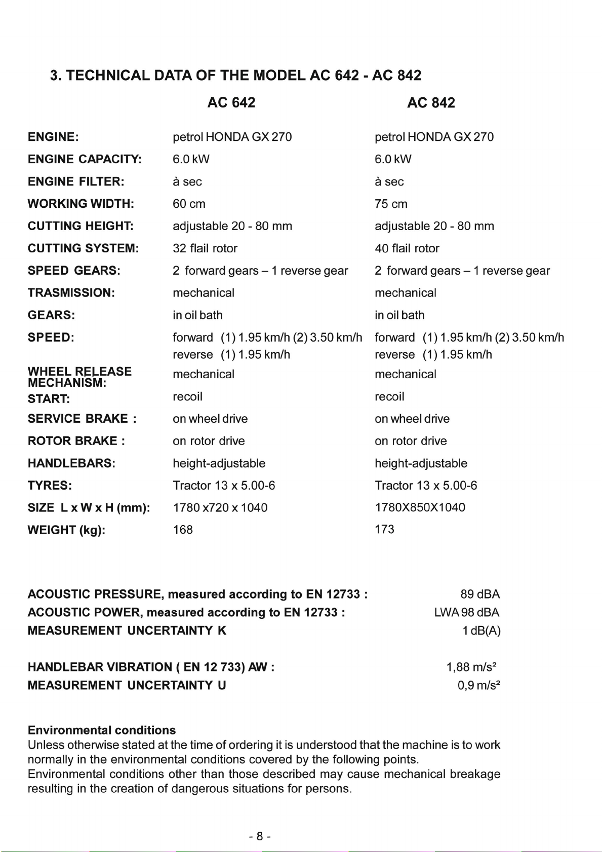
3. TECHNICAL DATA............................................................................page 8
4. LIFTING AND TRANSPORTATION.....................................................page 9
5. MAIN PARTS OF THE MACHINE........................................................page 10
6. CONTROLS AND ADJUSTMENTS.....................................................page 12
7. ASSEMBLY INSTRUCTIONS FOR THE HANDLEBARS AND
FRONT SUPPORT WITH WHEELS....................................................page 14
8. SAFETY INFORMATION
A) GENERAL INSTRUCITONS...........................................................page 15
B) TRAINING.....................................................................................page 15
C) PREPARATION..............................................................................page 15
D) WORKING USE.............................................................................page 16
E) AFTER WORK.............................................................................. page 17
9. TRANSPORTATION OF THE MACHINE..............................................page 18
10. SAFETY SYSTEMS AND GUARDS.....................................................page 19
11. OPERATIONS TO BE CARRIED OUT BEFORE SWITCHING ON....... page 19
12. STARTING AND DRIVING THE FLAIL MOWER................................. page 20
13. CUTTING TIPS...................................................................................page 22
14. CHECKS
A) TYRE PRESSURE.........................................................................page 22
B) CABLE CONTROL ADJUSTMENT................................................page 23
C) BRAKES ADJUSTMENT.................................................................page 25
D) BELT REPLACEMENT AND ADJUSTMENT...................................page 26
E) CHECKING AND REPLACING THE FLAILS..................................page 29
F) SHARPENING THE FLAILS...........................................................page 30
G) CHECKING AND REPLACING THE TRANSMISSION OIL.................. page 31
15. MAINTENANCE AND STORAGE.........................................................page 32
16. CLEANING THE MACHINE.................................................................page 33
17. SEASONAL LONG-TERM STORAGE PERIODS................................. page 33
18. DECOMMISSIONING AND SCRAPPING.............................................page 34
19. TECHNICAL ASSISTANCE................................................................page 34
20. WARRANTY......................................................................................page 34
21. CE MARKING....................................................................................page 35
22. TROUBLESHOOTING.........................................................................page 36
Enclosure 1. NOTES
Enclosure 2. Declaration of Conformity
- FLAIL MOWER MANUAL -
CONTENTS

FLAIL MOWER MOD. AC 642 - AC 842

- 5 -
2. NOTICE ON THE MACHINE
The symbols affixed to the machine serving to warn of danger during its use and
maintenance are as follows:
THE USER MUST READ THE INSTRUCTION MANUAL PROVIDED
DANGER OF FOREIGN OBJECTS BEING THROWN
OUTWARDS. KEEP A SAFE DISTANCE
ALWAYS DISCONNECT THE CABLE FROM THE ENGINE SPARK PLUG.
DANGER OF HAND INJURY. SWITCH OFF THE ENGINE

- 6 -
DANGER OF CRUSHING. KEEP A SAFE DISTANCE
DANGER OF INJURY TO BOTH UPPER AND LOWER LIMBS.
DO NOT PUT HANDS OR FEET INSIDE THE CUTTING
ELEMENT WHILE IN MOTION
DANGER OF GETTING CAUGHT UP IN ROTATING PARTS.
DO NOT PUT HANDS IN THE ROTATING PARTS
DANGER OF FOREIGN OBJECTS BEING THROWN OUTWARDS.
SAFETY GOGGLES MUST BE WORN

- 7 -
EAR MUFFS MUST BE WORN.
DO NOT ALLOW CHILDREN NEAR THE MACHINE
WHEN IN OPERATION.
CAUTION: HOT PARTS. DANGER OF BURNS. FIRE HAZARD
The symbols affixed to the machine serve to warn of danger during its use and maintenance.
It is vitally important to understand the meaning of the danger notices and all messages
should be kept in legible condition. In the instance of wear these no-tices should be
replaced and use of the machine suspended while without such notices.
The operator is advised to observe the warnings given on the affixed notices.

173
168

- 9 -
ALTITUDE
The altitude of the place in which the machine is to be used must not exceed 1500 m
above sea level.
TEMPERATURE
Minimum ambient temperature: -5°C
Maximum ambient temperature: +50°C
ATMOSPHERIC CONDITIONS
The electrical equipment will function correctly in atmospheric conditions with a relative
humidity up to 50% at a temperature of 40°C and at 90% with a temperature up to 20°C
(without condensate).
ATMOSPHERE WITH RISK OF EXPLOSION AND/OR FIRE
The standard machine herein described is not designed to work in explosive atmospheres
or in those with risk of fire.
4. LIFTING AND TRANSPORTATION
All material is carefully checked by the manufacturer before shipping. The flail mower is
delivered in a wooden crate or cardboard box with the handlebars and front support with
wheels disassembled.
Upon receipt of the machine make sure that it has not been damaged during transit and
that the packaging has not been tampered or any parts removed. Report any damage or
missing parts immediately to the driver and the manufacturer with photographic
documentation.
After assembling the handlebars, the front support with wheels and the safety bar as per
the instructions given in paragraph 7 of this manual, the machine may be moved on its
own wheels.
The manufacturer is not liable for any damage caused by transportation of the machine
after its delivery.
WARNING
Extreme care must be taken during handling to prevent overturning. Avoid steep gradi-
ents to prevent loss of control. Make sure that there are no persons present within the
danger area.

- 10 -
5. MAIN PARTS OF THE MACHINE
The machine consists of the following main parts:
A - FORWARD CLUTCH CONTROL LEVER
B - ACCELERATOR CONTROL LEVER
C - PINS TO BLOCK/RELEASE THE FRONT WHEELS
D - FLAIL ROTOR CLUTCH CONTROL LEVER
E - RIGHT WHEEL RELEASE LEVER
E1 - LEFT WHEEL RELEASE LEVER
F - ENGINE
G - FRONT WHEELS
H - FRONT GUARD
I - CUTTING HEIGHT ADJUSTMENT LEVER
M - ON/OFF SWITCH (1/0)
N - GEAR SELECTOR LEVER

- 11 -
Figure 1
Figure 2

- 12 -
6. CONTROLS AND ADJUSTMENTS
A) FORWARD CLUTCH CONTROL LEVER
This lever only has two positions: engage and disengage. Lowering the lever engages
the clutch and releasing it disengages the clutch. The service brake is connected to this
lever. The brake operates automatically when the clutch is disengaged.
B) ACCELERATOR CONTROL LEVER
This is used to adjust the number of engine revolutions according to the operations to be
carried out. Hence at switch on the lever will be positioned on the minimum setting whilst
during work operations it will be positioned as required by use.
C) PINS TO BLOCK/RELEASE THE FRONT WHEELS
The front wheels can turn freely when the pins are in the disengaged position.
When the pins are engaged in place on the fork supporting the wheel, the front wheels will
only move in one direction. Operate the flail mower with the pins engaged when working on
slopes to prevent the risk of slipping.
WARNING
Before changing direction, release the pins to disengage the front wheels
D) FLAIL ROTOR CLUTCH CONTROL LEVER
This is used to engage and disengage rotary movement of the flail holder rotor. Lowering the
lever engages the clutch and releasing it disengages the clutch. The flail brake is connected
to this lever, so the brake operates automatically when the lever is released and the rotor
stops within a few seconds.
WARNING
The flail rotor rotates at high speed if the engine is running and the flail clutch is engaged,
regardless of the position of the forward clutch.
E and E1) RIGHT AND LEFT WHEEL RELEASE LEVERS
These make directional gear changes easier during forward movement or manoeuvring of
the machine.
WARNING
Never use the release levers instead of the forward clutch control lever since release of the
two wheel release levers at the same time automatically disengages the service brake,
thus overriding its safety function. This precaution must be observed particularly when
working on steep banks.
G) FRONT WHEELS
These are the front support for the machine and they are involved in cutting height adjustment.

- 13 -
I) CUTTING HEIGHT ADJUSTMENT LEVER
This lever serves to adjust the cutting height. Warning: if the cutting height is set too low
the following undesirable consequences may occur:
-foreign objects such as stones, etc., may be thrown outwards
-dirt and mud may accumulate inside the rotor guard, thus impeding regular discharge
of cut grass.
-premature flail wear and possible breakage of the same.
M) ON SWITCH
Two-position switch:
(1) for starting the engine
(0) for switching off the engine
N) GEAR SELECTOR LEVER
This lever is used to select the forward speed of the machine.
The numbered positions indicate the speed settings (1st - 2nd) , the letter N indicates the
neutral gear and the letter R indicates the reverse gear.
WARNING
Be sure to set the lever position correctly (Fig. 2 Ref. N), making sure that the lever is
correctly engaged; if it is not, engage the forward clutch momentarily (Fig. 1 Ref. A) so that
the speed setting engages correctly.
The above operation may prove particularly useful during the machine's first working hours.
H) FRONT GUARD
The front guard (Fig. 1 Ref. H) opens or closes automatically according to the amount of
grass to be cut. Use of the machine with the guard left open is strictly prohibited. This may
cause the outward projection of objects.
The guard may only be set in the open position during flail replacement operations with the
machine switched off.

- 14 -
7. ASSEMBLY INSTRUCTIONS FOR THE FRONT SUPPORT
WITH WHEELS
The flail mower is delivered with the front support with wheels disassembled. Remove the
cardboard packaging or crate (to be disposed of in an appropriate manner, in accordance
with current regulations in force).
To assemble, proceed as follows :
Position the support with front wheels and connect the height adjustment piece (Fig. 3 ref.
D) using the screw and washer provided. Fix it to both sides of the bonnet as well using the
screws, washers and spacers provided, as shown in Fig. 3 ref. A.
Fix the safety bar ( Fig.3 ref. E ) to the special holes on the two front sides of the wheel
support using the screws, washers and nuts provided.
Before switching on ensure that the machine has been fully assembled correctly.
Figure 3

- 15 -
8. SAFETY INFORMATION
Before using the flail mower it is essential that the operator has understood the warnings,
do’s and don’ts and precautionary measures given in this manual and in the engine manual:
the prevention of injury to the operator, third parties, animals or objects directly depends
on observance of these instructions.
A) GENERAL INSTRUCTIONS
Use of the flail mower for purposes other than those envisaged is strictly prohibited.
Climbing aboard and/or riding on the flail mower is strictly prohibited.
Tampering with the safety systems and guards is strictly prohibited.
Modifications to devices/components not envisaged by the manufacturer are strictly
prohibited.
The electrical parts of the engine must be protected at all times.
B) TRAINING
Read the Operator’s Manual and the Engine Manual before using the machine.
Use of the machine by minors under the age of 16 years or by persons without the
necessary psychological and physical capabilities is forbidden.
Do not use the machine near other persons or within enclosed areas.
The placing of hands, other parts of the body and clothing in the moving parts of the
machine is prohibited.
It is forbidden to approach the moving parts.
Before carrying out any inspection or servicing operations make sure that the engine
has been switched off and the spark plug wire removed.
C) PREPARATION
Make sure that the working area around the machine is free of obstacles and has
sufficient lighting.
Before switching on the engine make sure there are no persons, animals or vehicles in
the vicinity.
Before switching on the engine make sure that both engagement levers (forward clutch
control lever - Fig. 1 Ref. A and flail clutch control lever - Fig. 1 Ref. D) are in the
disengaged position (released) ; the service brake will be on automatically; then place
the gear lever in neutral (see Fig. 2 Ref.N )
Before switching on the machine make sure that the screws, fixing elements and
protection devices are in place and that the affixed notices are legible.
Then: Make sure that the wheel fixing bolts have been tightened fully.
Secure all flail nuts and fixing bolts to prevent their loss during work operations. Replace
any old or worn flails.
The guard in front of the flails ( Fig. 1 Ref. H) must always be closed while the machine
is in use.
When switching on the engine check the position of the various control levers (see the
section on “Controls and adjustments”).
Supervise the clothing of personnel operating the machine: a long-sleeved jacket with
close-fitting cuffs, long, close-fitting trousers, heavy-duty footwear, and a protective
cap or helmet should be worn. Avoid wearing loose-tailed clothing, unbuttoned jackets
or torn, undone or partially zipped up items to prevent them from being caught up in
the moving parts.
Safety goggles and ear protection devices must be worn. Safety gloves must also be
worn during machine operation and maintenance.

- 16 -
Do not switch on and operate the flail mower in enclosed areas since the engine gives
off carbon monoxide fumes which are colourless, odourless, tasteless and extremely
dangerous.
Take care when handling fuel. Fuel is highly flammable and its vapours explosive :
-Only use an approved container.
-Take care not to remove fuel caps or top up the tank with the engine running.
-Allow the engine to cool before proceeding with fuel-filling operations.
-Do not smoke during this operation.
-Never fill the machine with fuel in an indoor ambient.
-It is advisable to use a wide funnel to prevent spillage of fuel on the engine and on
other surfaces of the flail mower.
-If any fuel is spilled do not attempt to switch on the engine; simply move the machine
away from the area of spillage before switching on.
-After filling up with fuel reposition and screw the fuel tank cap right down.
Do not rest the flail mower or the fuel container in indoor environments with naked
flames.
D) WORKING USE
When working keep everyone at a minimum distance of 10 metres from the machine.
Keep the engine well ventilated and clog-free (materials and other residue) to prevent
damage to the engine and risk of fire. Clean the cooling fan and fins regularly.
Clean the air filter at the same time as well.
Drive smoothly, avoiding brusque starts, braking and turns.
Take care not to touch the silencer when hot.
When reversing make sure there are no children or animals around. Take care not to
get caught up in the moving parts of the machine.
If a slipping belt causes abnormal noise, smells or overheating, switch off the engine
immediately and check the machine to prevent the outbreak of fire and damage to the
transmission.
The rotating flails are extremely dangerous. Keep away from the rotor guard when the
flails are in motion. Do not help the grass into the housing using hands or feet and do
not allow anyone to stand either in front of the machine or in its direction of travel.
WARNING
During work operations the grass is shredded and expelled by the machine. However, if
the grass is damp it tends to build up inside the flail housing, thus leading to the incorrect
feeding of the grass to be cut. The result is that even on short grass the engine may tend
to cut out. Remove the build-up of grass inside the housing (with the engine switched off)
using a stick of wood, or wait until the grass dries out before resuming cutting. If during
work operations the engine tends to stop due to overloading, either a slower gear must be
used or the cutting height must be increased, or else only part of the machine working
width must be used.

- 17 -
When working in a stony or obstacle-riddled area try to remove as many objects as
possible before commencing cutting. Then work at a greater cutting height than usual.
WARNING
Stones and other objects may be thrown outwards in direction of the operator or of other
persons in the vicinity. Keep at a safe distance from persons, animals and objects.
If the cutting mechanism accidentally comes into contact with an object (stump or
stone), switch off the engine and carry out the following operations:
-Inspect the damage.
-Do not attempt to repair it if unskilled to do so.
-Check that no parts have come loose.
Do not use the machine if it does not work properly or is broken: seek authorized
service.
It is strictly prohibited to leave the flail mower running whilst unsupervised.
It is strictly prohibited to transport the machine with the engine running. When loading
the machine onto a vehicle, the inclination of the ramps must not exceed 15°.
WARNING
EXERCISE CAUTION WITH GRADIENTS . Danger of machine overturning.
Given its outdoor use, it is advisable not to use the flail mower when it is raining.
The area next to the engine exhaust may reach a high temperature.
WARNING
Danger of burns.
Do not go near water fountains or precipices and do not cross narrow bridges during
work operations to prevent the risk of falling.
Do not work on steep banks with gradients in excess of 10°.
Take special care on steep banks; avoid working upstream of the machine so as not to
run the risk of slipping under it, particularly when the ground is wet.
Avoid working on the shoulder, between flat ground and a steep bank. The machine
may skid or slip.
In the instance of difficulty or emergency stop simply release the forward clutch control
and flail rotor levers.
Work on flat ground for the utmost safety.
E) AFTER USE
Before moving away from the machine, place the gear lever in neutral (Fig. 2 Ref.N)
and switch off the engine by moving the switch (Fig.2 Ref.M) to the 0 position.
For greater safety shut off the feed cock (Fig. 4).

- 18 -
9. TRANSPORTATION OF THE MACHINE
LOADING AND UNLOADING FROM A VEHICLE
For transportation it is pReferable to use a vehicle with an open bed.
Choose firm, flat ground.
Switch off the vehicle’s ignition, put into reverse gear, pull on the hand brake and block
the tyres with chocks to prevent accidental movement of the vehicle.
WARNING
Alzare al massimo il gruppo di taglio del trinciasarmenti , per evitare il rischio di pericolose
interferenze con i bordi delle rampe
Do not stand in front of the machine
Firmly hook the loading ramps onto the vehicle bed.
Use stable load ramps with a non-slip surface strong enough to take the weight of the
machine.
The inclination of the ramps must not exceed 15°.
Recommended length : at least 31/2 times the vehicle bed’s height from the ground.
Recommended width : to be chosen according to the tyre width of the machine
Proceed with the loading of the machine, manoeuvring it carefully. Set the accelerator
lever at minimum (Fig. 1 Ref. B) and the speed lever ( Fig. 2 Ref. N) to the 1st gear
setting
Using the lever as shown in Figure 2 Ref. N, engage the forward gear for loading, or the
reverse gear for unloading.
During loading/unloading operations on the ramps avoid operating the flail clutch (Fig. 1
Ref. D), the gear lever (Fig. 2 Ref. N) and the right and left wheel release levers (Fig. 1
Ref. E and E1) because such actions may prove extremely dangerous.
Line the front wheels up with the centre of the loading ramps.
Take care when the machine passes from the loading ramps to the vehicle bed, because
a shift in balance occurs.
Once loaded, turn off the engine using the relative switch (Fig. 2 Ref.M), make sure
that the service brake has automatically come into operation upon release of the forward
clutch control levers ( Fig. 1 Ref. A), block the machine wheels using chocks and firmly
tie the machine to the vehicle.

- 19 -
10. SAFETY AND GUARD SYSTEMS
WARNING
The safety devices must never be tampered with. It is necessary to understand how they
work and safeguard their efficiency and correct operation. In the instance of doubt, prob-
lems or malfunction contact your dealer.
FORWARD CONTROL AND FLAIL MOVEMENT LEVERS
When released both of these levers instantly disengage the transmission connected to them,
thus automatically engaging their respective brakes, hence the machine service brake in the
first case and flail rotor brake in the second.
In this way they act as safety devices.
In the instance of difficulty or sudden emergency, the quick release of these levers will
return them to their standard position (raised).
FRONT GUARD
The front guard (Fig. 1 Ref. H) opens or closes automatically according to the amount of
grass to be cut. Use of the machine with the guard left open is strictly prohibited. This may
cause the outward projection of objects.
The guard may only be set in the open position during flail replacement operations with
the machine switched off.
11. OPERATIONS TO BE CARRIED OUT BEFORE SWITCHING ON
Position the flail mower outdoors on sufficiently firm, flat soil. Read the instructions provided
by the engine manufacturer in the relative manual and follow them caRef.ully to prevent
situations arising which may endanger either persons or the machine.
Then check:
-the state of the flails by inspecting them;
-that all the screws are tightened, particularly those securing the flails;
-that the guards and safety devices are securely tightened.
-that there are no persons in the vicinity.
During operation do not allow persons near the machine, especially children. The operator
is responsible for any harm done persons in the working area of the machine.
Oil recommendations
Before switching on the engine check the oil level and top up, if necessary,
while keeping it in a horizontal position. Do not overfill.
Use of a high-grade detergent oil is recommended (Ref.er to the enclosed engine manual).
Fuel recommendations
Use of fresh, clean lead-free petrol is advised.
WARNING
It is advisable to consult the engine manual before swithcing on the machine.

- 20 -
12. STARTING AND DRIVING THE FLAIL MOWER
The machine can be switched on once all the aforementioned preliminary operations
have been carried out.
Place the feed cock in the OPEN position (direction shown by the arrow, Fig. 4).
Bring the choke to the CLOSED position for a cold start (direction shown by the arrow,
Fig. 4a).
Set the accelerator lever at the minimum position.
Grip the engine pull lead handle ( Fig. 4b ) and pull gently until you feel the “bite”, then
pull on the lead sharply to overcome the pressure, prevent kickback and switch on the
engine. Repeat the procedure, if necessary, with the accelerator lever in
INTERMEDIATE position. Once the engine is running, set the accelerator in the
MINIMUM position and gently return the choke to the OPEN position (Fig. 4a).
Cleaning of the machine is recommended after use (see the section “Cleaning the
machine”).
Figure 4 Figure 4a
Figure 4b
This manual suits for next models
1
Table of contents
Other Active Lawn Mower manuals