manuals.online logo
Brands
  1. Home
  2. •
  3. Brands
  4. •
  5. Air OPUS
  6. •
  7. Utility Vehicle
  8. •
  9. Air OPUS OP2 2020 User manual

Air OPUS OP2 2020 User manual

Other Air OPUS Utility Vehicle manuals

Air OPUS OP4 User guide

Air OPUS

Air OPUS OP4 User guide

Air OPUS OP2 User guide

Air OPUS

Air OPUS OP2 User guide

Popular Utility Vehicle manuals by other brands

Strautmann Giga-Trailer 1840 operating instructions

Strautmann

Strautmann Giga-Trailer 1840 operating instructions

FORS MW FARMA T 10 Instruction book

FORS MW

FORS MW FARMA T 10 Instruction book

pronovost PUMA-10000 Operator's manual

pronovost

pronovost PUMA-10000 Operator's manual

Polaris ACE 900 SP owner's manual

Polaris

Polaris ACE 900 SP owner's manual

TrailMax T-12-UR manual

TrailMax

TrailMax T-12-UR manual

Toro 07277 Workman 2110 Operator's manual

Toro

Toro 07277 Workman 2110 Operator's manual

Floe Cargo Max 9.5-73 Assembly instructions

Floe

Floe Cargo Max 9.5-73 Assembly instructions

Toro 07059TC Operator's manual

Toro

Toro 07059TC Operator's manual

Taylor-Dunn B0-050-00 Operation, t roubleshooting and replacement parts manual

Taylor-Dunn

Taylor-Dunn B0-050-00 Operation, t roubleshooting and replacement parts manual

Toro 133-7128 installation instructions

Toro

Toro 133-7128 installation instructions

Taylor-Dunn ET 3000 manual

Taylor-Dunn

Taylor-Dunn ET 3000 manual

Kayo S70 Assembly manual

Kayo

Kayo S70 Assembly manual

Cushman Turf Truckster 84069 Parts & maintenance manual

Cushman

Cushman Turf Truckster 84069 Parts & maintenance manual

Landoll 900D Series Operator's manual

Landoll

Landoll 900D Series Operator's manual

Westward Go-4 XTR Operator's manual

Westward

Westward Go-4 XTR Operator's manual

Club Car Carryall I 1999 owner's manual

Club Car

Club Car Carryall I 1999 owner's manual

Etnyre Street Flusher operation, maintenance, parts and safety manual

Etnyre

Etnyre Street Flusher operation, maintenance, parts and safety manual

Landoll 340 Operator's manual

Landoll

Landoll 340 Operator's manual

manuals.online logo
manuals.online logoBrands
  • About & Mission
  • Contact us
  • Privacy Policy
  • Terms and Conditions

Copyright 2025 Manuals.Online. All Rights Reserved.

SPECIFICATIONS - 2 SLEEPER
Electrical
Power Supply 12V & 120V
Towing 7-PIN rounded plug
Stereo System Stereo System with 2x speakers,
Radio, USB inputs, CD & DVD player
Battery 2x 100Ah deep cycle AGM batteries with 120V charger
Trailer Lights LED tail lights, clearance lights, internal lights, number
plate light, tool box lights, kitchen light, annex light
Tent/Canopy
Material 400GSM Micro Weave Poly Cotton
Tropical Roof Waterproof and UV Protective Tropical Roof
Annex Fully Enclosed Annex with removable doors & side walls
Awning Annex with doors & end walls removed
Ensuite Room Removable ensuite shower room with oor
Optional Accessories
Foldable Roof Rack Optional (maximum 500lbs. load capacity)
e-Go/Enduro Movers Remote controlled
LED Light Kit Flexible strip lighting system w/ dimmer switches
www.opuscamper.us
4
T ENT INFLA TION TECHNOLOGY
OWNERs MANUAL
2020 MODEL
SPECIFICATIONS - 2 SLEEPER
Electrical
Power Supply 12V & 120V
Towing 7-PIN rounded plug
Stereo System Stereo System with 2x speakers,
Radio, USB inputs, CD & DVD player
Battery 2x 100Ah deep cycle AGM batteries with 120V charger
Trailer Lights LED tail lights, clearance lights, internal lights, number
plate light, tool box lights, kitchen light, annex light
Tent/Canopy
Material 400GSM Micro Weave Poly Cotton
Tropical Roof Waterproof and UV Protective Tropical Roof
Annex Fully Enclosed Annex with removable doors & side walls
Awning Annex with doors & end walls removed
Ensuite Room Removable ensuite shower room with oor
Optional Accessories
Foldable Roof Rack Optional (maximum 500lbs. load capacity)
e-Go/Enduro Movers Remote controlled
LED Light Kit Flexible strip lighting system w/ dimmer switches
www.opuscamper.us
4
T ENT INFLA TION TECHNOLOGY
www.opuscamper.us
Vehicle Identication Number (VIN) Page 2
Specications Page 3 - 4
Dimensions Page 5
11 Quick Tips to set up your Air OPUS® Page 6 - 7
Hitching & Trailer Electrics Page 8
Air OPUS® Brake Set Up Page 9
Setting Up your Air OPUS® Camper Page 10 - 11
Understanding the Air OPUS® Switchboard Page 12
Understanding the air valves when setting up your Air OPUS® Camper Page 13
Air OPUS® Water System Page 14 -15
Air OPUS® Gas System Page 16
Air OPUS® 120 Volt Mains Power Page 17
Air OPUS® 12 Volt Power Page 18
Air OPUS® Fridge Slide Page 19
Setting up the Additional Day Bed Page 20
Installing your Air OPUS® Annex Page 21 - 23
Installing your Air OPUS® Ensuite Page 24
Air OPUS® Care & Maintenance Page 25 - 30
Air OPUS® Warranty Page 31 - 33
CONTENTS
www.opuscamper.us
1
T ENT INFLA TION TECHNOLOGY
PCT Patent Pending GB/2017/050391
Design registration No 201712810, No 201712811, No 201712812, No 201712813
VEHICLE IDENTIFICATION NUMBER (VIN)
About you Vehicle Identification Number
Every Air OPUS® has a Vehicle Identication Number (VIN). The VIN Plate can be found
on the exterior of your Air OPUS® to the left of the door secured, to the draw bar. We
recommend making a note of your VIN in the template below.
This will be required by insurance companies.
www.opuscamper.us
2
T ENT INFLA TION TECHNOLOGY
SPECIFICATIONS - 2 SLEEPER
Body Work Baked enamel nish
Box Material Main body aluminium frame & composite panel exterior,
with galvanlized steel chassis and draw bar
Dimension (Lid Closed) 16’2” x 6’8” x 5’1”
Dimension (Lid Open) 18’4” x 6’8” x 11’6”
Ground clearance 12.4”
Ride Height 5’1” (with cargo rack)
Chassis 1’7” x 6’1” x 2’4”
Drawbar 8’6” x 4’7” x 6”
King Size Bed 6’5” x 5’3”
Trailer Dry Weight 2777lbs
Tongue Weight 242lbs
GVWR 3970lbs
Load Capacity 1000lbs
Features
Hitch Articulating Lock’N’Roll Hitch
Suspension Independent Coil Spring Suspension
Shock Absorber Quad Shock: Dual Gas Shock Absorber per side
Kitchen Fully Stainless Steel Kitchen with 4 burner stove
& sink with electric tap with slide out extension
Water System 2 x Electric Water Pump
Water Tank 2 x Stainless Steel Tanks (20gal)
Water Tank Guard 1.5mm checker plate
Fridge Tray 3’6”L x 1’9”W x 1’8”H
Stabiliser Legs 4 x Drop down lockable
Jockey Wheel Adjustable height swing up
Jerry Can Holders 2 x 6gl
Gas Bottle Holders Twin 20gal adjustable gas rings
Stone Guard Front Surface coated with anti chip deadener
Wheels & Tires 16” Alloy Wheel 265/75R16 Off-Road Tires
Spare Wheel 16” Alloy Wheel 265/75R16 Off-Road Tire
Brake System 12” Electric brakes with hand brake and electric break
away switch
Lights LED
Portable Toilet Standard
External Shower Cold water supplied from tank
www.opuscamper.us
3
T ENT INFLA TION TECHNOLOGY
SPECIFICATIONS - 2 SLEEPER
Electrical
Power Supply 12V & 120V
Towing 7-PIN rounded plug
Stereo System Stereo System with 2x speakers,
Radio, USB inputs, CD & DVD player
Battery 2x 100Ah deep cycle AGM batteries with 120V charger
Trailer Lights LED tail lights, clearance lights, internal lights, number
plate light, tool box lights, kitchen light, annex light
Tent/Canopy
Material 400GSM Micro Weave Poly Cotton
Tropical Roof Waterproof and UV Protective Tropical Roof
Annex Fully Enclosed Annex with removable doors & side walls
Awning Annex with doors & end walls removed
Ensuite Room Removable ensuite shower room with oor
Optional Accessories
Foldable Roof Rack Optional (maximum 500lbs. load capacity)
e-Go/Enduro Movers Remote controlled
LED Light Kit Flexible strip lighting system w/ dimmer switches
www.opuscamper.us
4
T ENT INFLA TION TECHNOLOGY
4 SLEEPER
2
www.opuscamper.us
DIMENSIONS - 2 SLEEPER
18’4”
16’2”
5’1”
6’8”
11’6”
5’1”
www.opuscamper.us
5
T ENT INFLA TION TECHNOLOGY
4 SLEEPER
2
www.opuscamper.us
Tip 1 - Invest in a cordless drill and
19mm hex head bit to adjust stabiliser
legs rather than manually winding them.
11 Quick Tips to set up and pack up your Air OPUS®
Tip 4 - When
operating the
winches ensure
that the winch
strap remains at
when using or
retracting.
.
Tip 3 - You can adjust the latch by
turning it along the thread, thus extending
it to avoid excessive pressure on the
latches. You can close your camper with
the latches longer, and then return to
tighten these up.
Tip 6 - When using your key to open and
unlock the door, push the door inwards
on the seal to take pressure off the lock
and it will open easier for you.
Tip 5 - Take special care to ensure
all canvas is tucked away on all sides
especially around gas struts, hinge points.
Tip 2 - To avoid placing too much
pressure on the latches and breaking
the latch hook, make sure you latch
down the back of the camper rst
(furthest from the hinge).
www.opuscamper.us
6
T ENT INFLA TION TECHNOLOGY
4 SLEEPER
2
www.opuscamper.us
11 Quick Tips to set up and pack up your Air OPUS®
Tip 7 - During canopy ination make sure all external air valves are closed off and the main air
valve is open before turning air pump on.
Tip 8 - During annex ination make sure the air valves are closed off before turning air pump
on BUT MAKE SURE the cross filling tube valve is OPEN so that the air from the canopy can
purge/travel through to the air beams on to help.
Tip 9 - Remember to turn the
MAIN INFLATION valve in the
camper to the horizontal CLOSED
position when ination is complete
otherwise the canopy may slowly
deate over time.
Tip 10 - If the beams are losing air slightly you can turn the
inbuilt air pump ON and that will top up the air pressure in
all air beams back to the desired pressure, the pump will
turn OFF automatically. If you have a separate pump tube
and valve, ensure the pump is removed and the valve is fully
closed shut.
Tip 11 - Before you set off on your rst trip, do a couple of full set ups and while you have all
the canopy and annex up, remember to weather-in the canvas and allow to dry completely
before packing up!
To OPEN valve turn counter clockwise.
To CLOSE valve turn clockwise until firm.
External Inflating /
DeflatingAir Valve
OPEN
CLOSED
www.opuscamper.us
7
T ENT INFLA TION TECHNOLOGY
CLOSE VALVE
REMOVE PUMP
About your Hitch
The Air OPUS®comes with a articulating
Lock’N’Roll hitch.
When hitching the Air OPUS®to your towing
vehicle you must ensure that someone is close
to the handbrake in order to maintain control
of the trailer, particularly when maneuvering
on uneven ground or a slope.
About your Electrical Plugs
7 PIN ROUNDED PLUG
The Air OPUS®is tted with a 7-pin rounded
plug that connects all the exterior trailer lighting
and the electric brakes to the towing vehicle.
A standard 7 pin plug is required on your tow
vehicle for this to connect to.
Disconnect these plugs when the engine of the
towing vehicle is not running, as it will continue
to draw current and you may end up with a
flat battery on your towing vehicle.
The 7-pin rounded plug runs through its own
resetable fused system located in the battery
compartment.
SOLAR PORT
You can also use the solar panel port to
attach a solar panel which will also charge your
Air OPUS®batteries. The solar panel must have a
built in charge regulator.
We recommend using any solar panel of at least
110W. Anything over 200W will be excessive as
you will not be draining your battery at such a
heightened rate.
HITCHING & TRAILER ELECTRICS
IMPORTANT
Wheel nuts should be checked
after first 100mi and then
every 2000mi.
www.opuscamper.us
8
T ENT INFLA TION TECHNOLOGY
Air OPUS® BRAKE SET UP
About your Brakes
The Air OPUS® is tted with electric trailer
brakes. You need an electric brake controller
tted to your car in order to tow the
Air OPUS® and operate the electric
brakes safely. Before departing, place car in
drive and check that the Air OPUS® brakes are
on. Refer to brake controller user manual for
correct adjustment.
BREAK-AWAY SWITCH
Your camper comes with a break-away
switch. This is a safety device which will
apply the trailer brakes if it becomes
disconnected from the tow vehicle
MAINTENANCE
As part of the annual service check you
should have completed by an accredited
industry service agent, the brakes should be
checked and maintained.
IMPORTANT
The break-away switch is not a security
device! When cable is pulled, switch
will drain power from batteries
www.opuscamper.us
9
T ENT INFLA TION TECHNOLOGY
Initial Steps
STEP 1 - Once you have positioned & leveled your
Air OPUS® on at ground (leveling wedges may be
required - not supplied), engage the handbrake &
disconnect hitch, wiring & chains from tow vehicle.
STEP 2 - Raise or lower the jockey wheel to level
your Air OPUS® lengthways.
STEP 3 - Using the leg winder supplied, gently
lower corner steady legs until each touches the
ground with enough pressure to stop any rocking.
STEP 4 - If you have a drop down spare wheel set
up, please adhere to these safety requirements.
Unclip the spare wheel carrier and lower it down
gently to the horizontal position, taking care to
support the weight of the spare wheel carrier so
that it does not swing free and fall.
SETTING UP YOUR Air OPUS®CAMPER
IMPORTANT
Corner support legs are only to
support the Air OPUS®NOT to be
used to level or lift.
STEP 5 - If roof rack is tted,
remove D Clips and unlatch the
2 retaining clips. Once rack is free
push up until the gas struts take
the weight. From the other side
of the camper pull roof rack
into vertical position and secure
upright with D clips through
mounting point.
www.opuscamper.us
10
T ENT INFLA TION TECHNOLOGY
Initial Steps
STEP 6 - Unlatch the lid starting at the rear of the camper. Lift the lid 20cm.
STEP 7 - Unwind the front winch until the strap is long
enough to reach the back of the camper. Clamp the winch
onto the rear eyelet mounted on the back of the lid. Unwind
the rear supporting winch and clip on with enough slack to
allow the lid to rise to vertical.
STEP 8 - Ensuring that the strap remains at and tensioned,
slowly wind the winch in to bring the lid up and over the
camper. The gas struts will take the weight of the lid.
STEP 12
Ensure the main internal air valve is open (vertical/inline). Tighten all
external air valves on each air beam (5 on tent and 7 on annex).
STEP 13
Turn the power key ON. Turn the pump master switch ON. Push the
pump button and watch your camper inate!
STEP 14
CLOSE the main internal valve to lock off air system. You may also wish
to close your cross linking valves to retain constant pressure over an
extended stay.
SETTING UP YOUR Air OPUS®CAMPER
IMPORTANT
STEP 9 - Once lid is fully open and resting against stone
guard secure in place using latch provided
STEP 10 - At this stage walk around the Air OPUS®and
inspect the tent to ensure that the canvas is properly
located within the aluminium channels and that no part
of the tent is caught or snagged.
STEP 11 - At front of camper t each corner of the
canvas over the corner of the lid. The seam on the
canvas should line up with each corner of the bed lid.
Secure using straps provided.
Take care not to stand underneath the lid as it comes down.
Ensure lid is lowered slowly & does not drop suddenly.
REPEAT STEPS 1-12
IN REVERSE TO PACK
AWAY. REMEMBER TO
ZIP UP YOUR DOORS
AND WINDOWS &
OPEN MAIN VALVE
BEFORE DEFLATING
CAMPER.
www.opuscamper.us
11
T ENT INFLA TION TECHNOLOGY
UNDERSTANDING THE Air OPUS® SWITCHBOARD
Main features of your switchboard
1 Main Power Key Switch
2 Front Pump
3 Rear Pump
4 Fridge Master Switch
5 Lighting Master Switch
6 Front Tank Indicator
7 Rear Tank Indicator
Quick steps to turn Air
pump on for inflation
Step 1 - Turn main power key switch ON
Step 2 - Turn air pump master switch ON
Step 3 - PRESS air ination button ON and
release, then pump will turn off
automatically once at desired pressure.
Quick steps to check
battery level
Step 1 - Turn on main power switch
Step 2 - Look at digital volt gauge
Step 3 - Look at battery level indicator
30v Circuit Breaker
Located inside the camper
36 11 10 7 122 4 5 114
8 Air Pump Master Switch
9 Air Ination Button
10 Battery Level Indicator
11 Volt/amp Gauge
12 12V Circuit Breaker Reset
13 12V Master Circuit Breaker
14 12V Power Outlet
8 9 13
IMPORTANT Your main inflation valve must be open/in line for your
pump to run. DO NOT hold the button in if it shuts off when
pressed or you will risk damaging your pump.
www.opuscamper.us
12
T ENT INFLA TION TECHNOLOGY
UNDERSTANDING THE AIR VALVES WHEN
SETTING UP YOUR Air OPUS®CAMPER
Check all 5 outside valves are closed. When inflating turn the Main
Inflation valve switch (inside
camper) to a Vertical OPEN
position by rotating
anticlockwise.
Open switch board, turn on main 12v power
key, switch main air pump switch to on, press
inflation button.
Once inflation is completete turn the Main
Inflation valve switch (inside camper) to a
Horizontal CLOSED position by rotating clockwise.
IMPORTANT
Failure to CLOSE the Main inflation
valve switch after inflation will
cause the Annex and Canopy to
slowly deflate.
Valve Cap
Air Valve /
Deation Valve
Tube/
Retaining Ring
OPEN
(vertical/in line)
CLOSED
(perpindicular)
1 2
3
4
www.opuscamper.us
13
T ENT INFLA TION TECHNOLOGY
Water System Set up
The Air OPUS® is tted with two fresh water tanks, with one unit mounted in front
of the axle and the other unit mounted behind the axle. Each water tank has its
own lockable ll point located on the driver side of the body of the Air OPUS® and is
plumbed to a 12v switchable water pump located on the circuit board.
Each tank has its own pump, each tank is stand alone.
Air OPUS®WATER SYSTEM
One tank supplies water to the driver’s shower side outlet behind the wheels and the
shower also located in this area. There is also the capability to connect mains water to
your inlet but you will require an external water regulator to avoid damaging your
system. The other tank supplies water to the slide out kitchen. There is also a water
outlet located next to the tank outlet connector.
The water tting closest to the rear of the camper on either side is your tank outlet. The
water tting closest to the front of the camper on either side is your inlet/cross lling tube.
Remove the red dust cap from the tting before activating the pump to ensure the
tting is not engaged and your water doesn’t pump out.
To use an opposing tank, simply plumb the inlet and outlet together on the side you
wish to plumb from and run the pump for the tank corresponding to that side. Then,
connect the blue hose on the opposing side you require water at to the outlet closest
to the front of the camper.
www.opuscamper.us
14
T ENT INFLA TION TECHNOLOGY
The kitchen sink is connected with a short hose with tting attached, this is to be plugged
into the water outlet connection on the Air OPUS® and the water intake on the kitchen,
which is only accessible when the kitchen is fully extended.
The kitchen has a drain hose attached to the sink drain. This is designed to drain cold
water to a waste container/bucket as the Air OPUS® is a cold water unit.
The water pumps are pressure operated, so once the main 12 Volt power switch is turned
on at the circuit board, the pump will prime the system and as soon as you turn the tap on
the water will ow. Once the tap is closed the pump will turn off until the tap is turned
back on.
When the water system is not required Air OPUS® recommends to switch off the pump
when not in use.
When packing away the Air OPUS® follow the procedure below in order to drain the
system of any excess water before disconnecting the water inlet and internal waste pipe:
A. Switch off the pump at the mains power switch.
B. Open the tap & allow the excess water in the pipe to drain.
C. Close the tap once all of the water has drained.
D. Disconnect either side of the male-to-male hose coupler.
E. Place the bottom waste water outlet pipe away under sink.
Draining your Tanks prior to storage
DO NOT use your pumps to drain your tanks - running the pumps until the tank
is dry will damage your pumps and will not be covered by warranty. Use the drain
point/sump plug on the underside of the tank. For further storage information refer to the
STORING YOUR OPUS section in this handbook.
IMPORTANT
A SMALL AMOUNT
OF WATER MAY BE
PRESENT FROM THE
CONNECTORS AND
WASTE HOSE, SO
A CLOTH IS USEFUL
TO REMOVE ANY
EXCESS WATER.
Air OPUS®WATER SYSTEM
www.opuscamper.us
15
T ENT INFLA TION TECHNOLOGY
IMPORTANT
CHECK THE INSTRUCTIONS FOR
CORRECT FITMENT AND SAFE
USE WITH THE GAS CYLINDER
MANUFACTURER/SUPPLIER.
Air OPUS®GAS SYSTEM
Safe operating procedures for your gas system
STEP 1. The Air OPUS® is tted with rings for two 20lb
gas bottles. One bottle at a time can be connected via
the gas regulator provided and must be turned off when
the gas is not in use.
STEP 2. To install a gas cylinder, ensure the gas cylinder is placed correctly with J-clamp,
attach the threaded gas line to the bottle ensuring that’s its been tightened so no leaks occur.
It is advisable to keep an adjustable spanner with jaw opening up to 30mm for this use.
STEP 3. Once kitchen has been pulled out all the way you can t the gas bayonet hose to the
bayonet. This is a simple push and twist to install.
STEP 4. The gas tap/valve on the top of the gas bottle can now be opened. Allow 5 minutes for
gas to plumb through.
STEP 5. Turn on the yellow gas tap (situated underneath the rear of the OPUS behind each of the
gas outlets unit) by turning 90° until it’s in -line with the gas hose.
STEP 6. Lift up lid of the gas hob, turn on one of the burners (push in, hold the knob down until
ame is lit and stays on. Keep pressing the button until the gas has had time to ll up the system
and the burner will ignite.
STEP 7. Switch off the yellow gas valve when not in use and ensure that the gas bottle valve is
closed prior to packing up the Air OPUS® for transit or storage.
When Annex is being used, ensure sure both ventilation points are clear and not covered, one
on the drop skirt and the other on the roof of the rear pod. Leave the privacy screen behind your
kitchen OPEN.
Gas fumes inside a camper trailer tent could result in unconsciousness, brain damage or even
death. Follow safe operating procedures with gas at all times:
• Ensure good ventilation throughout, at ALL times
• Do not use any other gas systems than those provided with
the Air OPUS®camper inside the tent
• Always turn off the shut off valve IMMEDIATELY after use.
TIP - If your igniter on your stove is not clicking, check your D battery hasn’t dislodged.
You can do this by removing your cutlery drawer, and the D battery is tucked under
the front of the stove top beneath the bottom right burner. This battery may lose
contact or become dislodged during transit.
www.opuscamper.us
16
T ENT INFLA TION TECHNOLOGY
Air OPUS®120V & 12V POWER SYSTEM
120V Shore Power Connection - Safe operating procedures
The OPUS® comes tted with a 120 volt power system. This 120 Volt power system complies
with NFPA regulations.
The main circuit breaker and panel is located in the electrics cupboard accessibly externally
to the left of the door, behind the main cupboard center door on the driver’s side. Always
ensure you have a clear access to the cupboard door and it is not blocked at any time.
The Shore power hookup is located on the driver’s side at the front of the OPUS®. There are
three internal 120v power points.
• Behind the main circuit board. This unit is designed to supply the battery charger.
• In the storage next to the door
• In the storage area behind the seating area next to the front bed.
www.opuscamper.us
17
T ENT INFLA TION TECHNOLOGY
12V Power - Safe operating procedures
The OPUS® has many 12v outlets they are a combination of standard 12v sockets, mini 12v
sockets, USB sockets and switches.
You will nd their location as follows:
• In the front tool box / fridge compartment there is a standard 12v socket. In the same
area there is a small switch that operates the fan located in the door (if tted on this
model)
• On both sides of the tool box there is an LED work light. This has an automatic on/off
switch
• Inside the OPUS® there are four 12v mini sockets. These are for the 12v LED lights at
the bed end. Above the main circuit board there is a twin 12v USB socket.
• Externally at the rear passage side next to the kitchen slide-out there are two additional
12v mini sockets and a standard 12v socket. The two mini sockets are designed to
operate the 12v LED light on the kitchen and a small annex light.
12 Volt - Safe operating procedures
The Air OPUS®has many 12V outlets - they are a combination of standard 12V
sockets,12V light sockets, USB sockets and switches. These are located throughout
your camper trailer both internally and externally.
Next to the main door you will nd your stereo system, light switch and dimmers for
internal and external xed body lighting. The dimmers will only operate the build-in
lighting and will not inuence any other lighting you run via sockets.
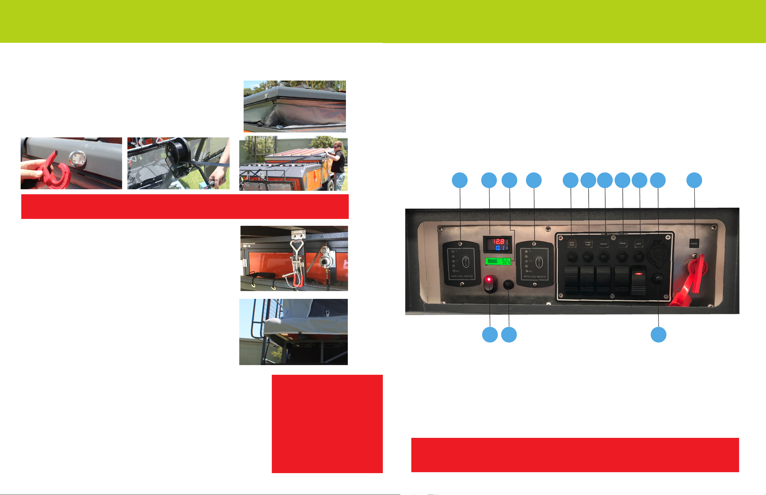
The control panel has a battery volt-meter that will provide an indication of the remaining
charge of the batteries and amp draw display in real time. A full battery will be indicated
by the Battery Level Indicator.
There are also two water tank gauges which will display the water level when pressed.
All switches have their own resetable fuse next to each of the switches in addition toa
master resetable circuit breaker for the whole 12V system located next to these controls.
Your batteries are also fused - in the battery compartment the large resettable fuse is
wired to the 7-pin wiring harness tted at the drawbar.
All sockets, fridge power and lighting will operate on 12V power from the on board
batteries; heavy usage and power hungry appliances will deplete the battery’s charge.
It is recommended to have the mains 120V connected to a suitable supply if available,
even if appliances are run on 12V only, to ensure your batteries remain topped up.
The battery charger is fully automatic and will recharge the batteries if the
Air OPUS®is connected to an 120V electric power supply via the 30amp power inlet.
Do not unplug or disconnect this charger internally as it may lose memory settings
for your battery set up and affect your charging. This is an automatic cycle charger and
if using, allow enough time for the charger to complete a full charge cycle.
Regular battery maintenance checks (charge once a month) will prolong the life of
your battery as AGM/Deep Cycle Batteries do not like to be drained at.
Refer to your battery charger instruction manual for further details.
Air OPUS®12 VOLT POWER
18 www.opuscamper.us
T ENT INFLA TION TECHNOLOGY
IMPORTANT
Your towing vehicle must have an in-car electric brake
controller installed or your warranty will be voided.
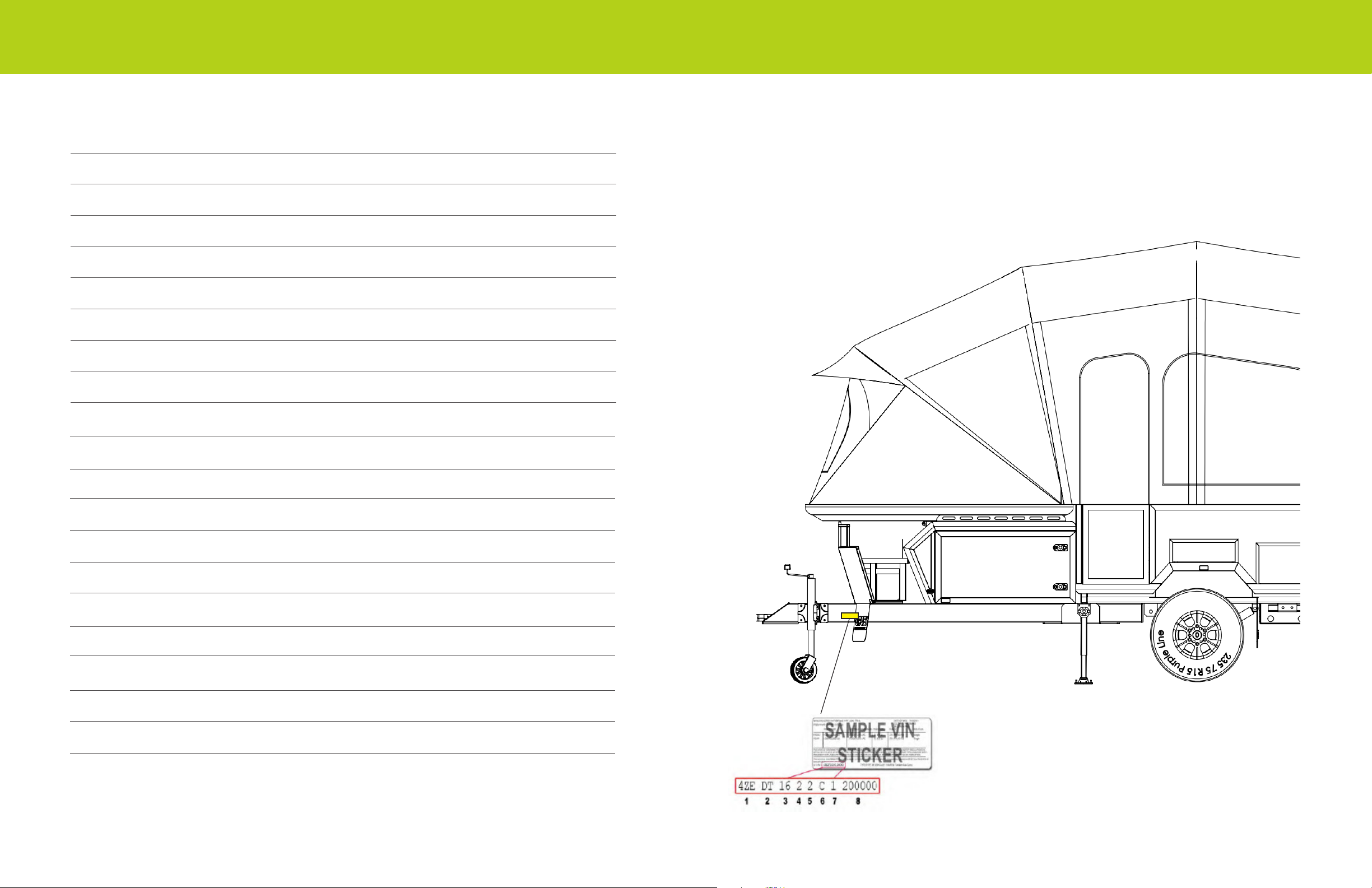
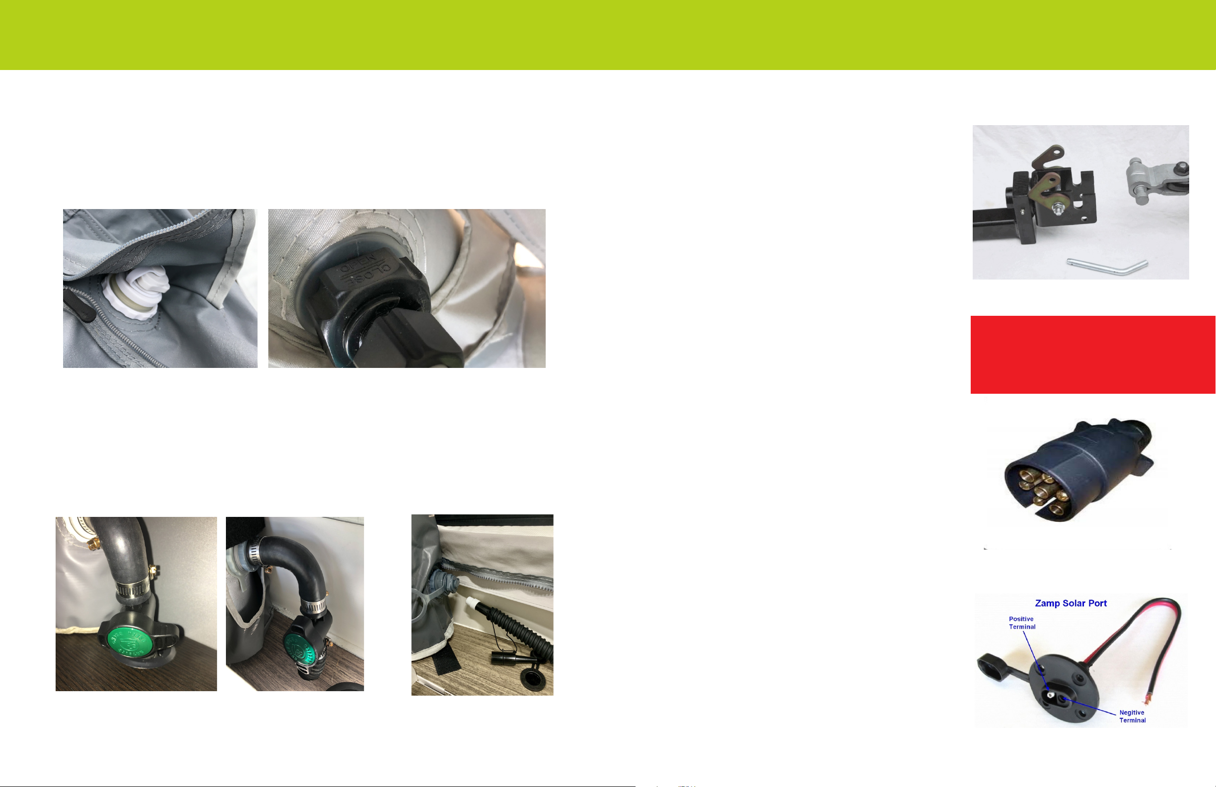
TOWING WIRING
The trailer lights and electric brakes are wired to a standard 7 pin trailer plug.
The Air OPUS® is fitted with electric brakes. While in transit if the tow vehicle has the
7-pin connected this will also be topping up the batteries.