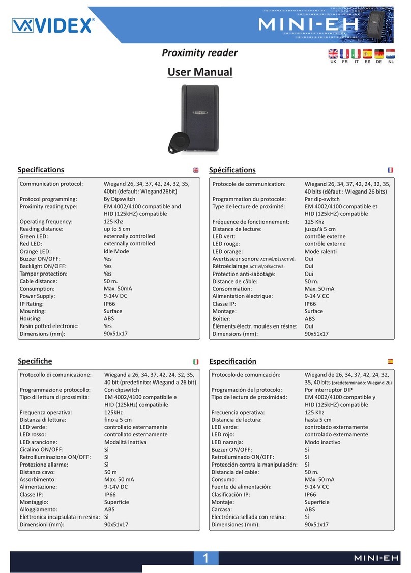
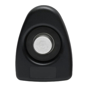
ACTpro 1030e User manual

pro
ACTpro Readers
Installation Manual
ACTpro 1040eACTpro 1030e ACTpro 1050e/1060e
Slimline Proximity
Reader
Proximity Reader PIN & Proximity Reader/
PIN only Reader

ACTpro Readers Installation Manual
Copyright © 2016 Access Control Technology Ltd. Part No.18-00106 Issue 0
FCC STATEMENTS
ACTpro 1030e ACTpro 1040e ACTpro 1050e
Model No. RF-1030 RF-1040 RF-1050
FCC ID 2AILRRF1030 2AILRRF1040 2AILRRF1050
ACTpro 1060e
Model No. RF-1060
This device complies with part 15 of the FCC Rules. Operation is subject to the
following two conditions: (1) this device may not cause harmful interference, and
(2) this device must accept any interference received, including interference that
may cause undesired operation.
Note: This equipment has been tested and found to comply with the limits for
a Class A digital device, pursuant to part 15 of the FCC Rules. These limits are
designed to provide reasonable protection against harmful interference when the
equipment is operated in a commercial environment. This equipment generates,
uses, and can radiate radio frequency energy and, if not installed and used in
accordance with the instruction manual, may cause harmful interference to radio
communications.
Operation of this equipment in a residential area is likely to cause harmful inter-
ference in which case the user will be required to correct the interference at his
own expense.

ACTpro Readers Installation Manual
Copyright © 2016 Access Control Technology Ltd. Part No.18-00106 Issue 0
ACTpro 1030e ACTpro 1040e ACTpro 1050e ACTpro 1060e
Connections Pigtail Terminal Block Terminal Block Terminal Block
Dimensions
W x H x D
1 7/16” x 4 3/4”
x 9/16”
37mm x
120mm x
15mm
3 3/4” x 5 1/16”
x 3/4”
95mm x 128mm
x 19mm
3 3/4” x 5 1/16”
x 13/16”
95mm x 128mm
x 21mm
3 3/4” x 5 1/16”
x 13/16”
95mm x 128mm
x 21mm
Mounting Mullion Flush or
Surface
Flush or
Surface
Flush or
Surface
Power Supply 5Vdc-16Vdc 5Vdc-16Vdc 5Vdc-16Vdc 5Vdc-16Vdc
Current
Consumption 75mA 75mA 100mA 75mA
Operating
Temperature
-4°F/122°F
-10°C/50°C
-4°F/122°F
-10°C/50°C
-4°F/122°F
-10°C/50°C
-4°F/122°F
-10°C/50°C
Transmit
Frequency 125Khz 125Khz 125Khz NA
Keypad No No Yes Yes
Environmental
Rating IP67 IP67 IP67 IP67
Cable
Distance
300ft
100 m
300ft
100 m
300ft
100 m
300ft
100 m
Output
Formats
Wiegand or
Clock & Data
Wiegand or
Clock & Data
Wiegand or
Clock & Data
Wiegand or
Clock & Data
Indoor &
Outdoor Yes Yes Yes Yes
Standards CE/FCC
Certied
CE/FCC
Certied
CE/FCC
Certied CE/FCC
1.0 Specifications Table

ACTpro Readers Installation Manual
Copyright © 2016 Access Control Technology Ltd. Part No.18-00106 Issue 0
Reader Connections - ACTpro 1040e/1050e/1060e
0V / GND
RED LED
GRN LED
BUZZ CTRL
5-12V DC
Data/D0
CLOCK / D1
SENSE
1050e/1060e Backlight Select
Top PINS = Backlight On
Bottom PINS = Backlight Off
Product Description
ACTpro RFID readers are 125Khz readers that support all ACT RFID
cards and fobs and HID-compatible tokens.
• Compatible with ACT RFID cards and fobs.
• Compatible with HID Clock and Data and Wiegand cards/fobs.
• Features a buzzer and an LED indication.
• Can be congured for Clock and Data or Wiegand output.
• Compatible with all standard access control systems.

ACTpro Readers Installation Manual
Copyright © 2016 Access Control Technology Ltd. Part No.18-00106 Issue 0
Reader Connections - ACTpro 1030e
ACTpro 1030e is supplied with 9ft/3m pigtail cable.
CAT 5/6 Colour Code
The following is suggested colour coding if using CAT5 or CAT6 cabling.
Reader
Output
Colour
Sense White/Green
Clock / D1 Green
Data / D0 Blue
+12V Orange
(0V) GND White/Orange
Red LED Brown
Green LED White/Brown
CLOCK/D1 (Green)
SENSE (White)
DATA/D0 (Blue)
+12V (Red)
0V/GND (Black)
RED LED (Brown)
GREEN LED (Yellow)
BUZZER (Orange)

ACTpro Readers Installation Manual
Copyright © 2016 Access Control Technology Ltd. Part No.18-00106 Issue 0
Clock & Data Entry Reader - Wiring
Clock & Data Exit Reader - Wiring
SENSE (White)
CLOCK / D1 (Green)
DATA / D0 (Blue)
+12V (Red)
OV / GND (Black)
RED (Brown)
GREEN (Yellow)
BUZZER INPUT
SENSE (White)
CLOCK / D1 (Green)
DATA / D0 (Blue)
+12V (Red)
OV / GND (Black)
RED (Brown)
GREEN (Yellow)
BUZZER INPUT
DO NOT CONNECT SENSE (White cable)
NB: Illustrations apply to all ACTpro readers

ACTpro Readers Installation Manual
Copyright © 2016 Access Control Technology Ltd. Part No.18-00106 Issue 0
WIEGAND Entry Reader - Wiring
WIEGAND Exit Reader - Wiring
SENSE
CLOCK / D1 (Green)
DATA / D0 (Blue)
+12V (Red)
OV / GND (Black, White)
RED (Brown)
GREEN (Yellow)
CONNECT TO BUZZER
SENSE (Blue)
CLOCK / D1 (Green)
DATA / D0
+12V (Red)
OV / GND (Black, White)
RED (Brown)
GREEN (Yellow)
CONNECT TO BUZZER
IMPORTANT: To put ACT readers into wiegand mode
connect the SENSE on the reader to 0V/GND.
IMPORTANT: To put ACT readers into wiegand mode
connect the SENSE on the reader to 0V/GND PIN and
DATA/D0 to the SENSE PIN on the controller.

ACTpro Readers Installation Manual
Copyright © 2016 Access Control Technology Ltd. Part No.18-00106 Issue 0
ACTpro 1030e Mounting Diagram
Screw unit to the surface.
Place caps onto the unit and
push firmly into place

ACTpro Readers Installation Manual
Copyright © 2016 Access Control Technology Ltd. Part No.18-00106 Issue 0
ACTpro 1040e/1050e/1060e
Surface Mount Diagram
Place the reader / keypad onto the surface
mount collar and clip down into place. Use
the security screw supplied to attach the unit
to the surface mount collar.
The surface mount collar is mounted on the
wall using the fixing kit supplied in the box.
Security screw
supplied with the unit
Place the cap onto the unit
and push firmly in place

ACTpro Readers Installation Manual
Copyright © 2016 Access Control Technology Ltd. Part No.18-00106 Issue 0
ACTpro 1040e/1050e/1060e
Flush Mount Diagram
Security screw
supplied with the unit
Remove spacers
before mounting
Place the cap onto the unit
and push firmly in place
Place the reader / keypad onto the flush
mount collar and clip down into place. Use
the security screw supplied to attach the unit
to the flush mount collar.
The flush mount collar is mounted on the wall
using the fixing kit supplied in the box. Prepare
the mounting surface to receive sub-surface
terminals.

ACTpro Readers Installation Manual
Copyright © 2016 Access Control Technology Ltd. Part No.18-00106 Issue 0
ACTpro 1040e/1050e/1060e
Flush Mounting to UK Pattress Box
Mounting plate is attached to the pattress
using the
screws supplied.
Ensure the correct spacers have
been used to bridge the gap between the mounting
plate and the fixing wings of the pattress
box to avoid
the mounting plate being distorted.
Place the reader / keypad onto the
surface mount collar and clip
down into place. Use the security
screw supplied to attach the unit
to the flush mount collar.
Security screw
supplied with the unit
Screws
Standard
pattress box
Place the cap onto the unit
and push firmly in place
Note:
Determine the distance between the pattress box
and the mounting plate, using the spacers that are
labelled 1mm to 4mm. A spacer of the correct
length is assembled by stacking the spacers
together.
Spacers break away
from main component
when required by
installer for use
View showing spacer
stacking
View shows mounting
plate before spacers are
broken away by installer

Ireland Ofce
Unit C1, South City Business Centre,
Tallaght, Dublin, D24 PN28, Ireland
United Kingdom Ofce
601 Birchwood One, Dewhurst Road,
Birchwood, Warrington, WA3 7GB, UK
Ireland: +353 (0)1 466 2570
UK: +44 (0)161 236 9488
Email: [email protected]
www.act.eu
www.act-access.com (USA)
Copyright © 2016 Access Control Technology Ltd. Part No. 18-00106 Issue 0
Access Control Technology Ltd.
reserve the right to change the
contents of this manual and the
system it applies to without prior
notice.
While every effort has been taken
by ACT to ensure the accuracy of
the information contained within
this document, ACT assumes no
responsibility for any errors or
omissions. No liability is assumed
for damages resulting from the
use of information contained
within this document.
This manual suits for next models
3
Table of contents

