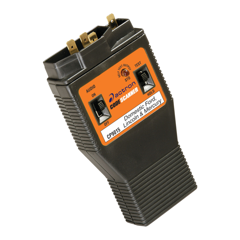
Actron Code Scanner CP9025 User manual

1
T
M
Congratulations on purchasing your
Actron Code Scanner for accessing
engine trouble codes required for
repairing vehicles equipped with
computers. YourActron Code Scanner is
made by Actron, the largest and most
trusted name in automotive diagnostic
equipment for the home mechanic. You
can have confidence this product
maintains the highest quality in
manufacturing, and will provide you
years of reliable service.
This instruction manual is divided into
several key sections. You will find
detailed steps on using the Code
Scanner and important information
about trouble code meanings, how a
computer controls engine operation, and
more!
Identifying the problem is the first step in
solving that problem. YourActron Code
Scanner can help you determine by
accessing the engine computer trouble
codes. Armed with that knowledge, you
can either refer to an appropriate service
manual or discuss your problem with a
knowledgeable service technician. In
either event you can save yourself a lot
of valuable time and money in auto
repair.And feel confident that your
vehicle’s problem has been fixed!
Actron offers a compete
line of high quality
automotive diagnostic and
repair equipment.
See your local Actron
dealer for other
Actron products.
CONTENTS
1About Codes................................... 3
2When to Read Codes..................... 5
3Using Codes................................... 7
TOYOTA SECTION
4Vehicle Preparation ........................ 9
5Reading Codes............................. 11
6Code Meanings ............................ 22
HONDA SECTION
7Vehicle Preparation ...................... 28
8Reading Codes............................. 30
9Code Meanings ............................ 40
NISSAN SECTION
10 Vehicle Preparation ...................... 43
11 Reading Codes............................. 46
12 Code Meanings ............................ 72
REFERENCE SECTION
13 Computer Basics .......................... 74
14 Glossary ....................................... 79
CP9 25
Instrucciónes en español ....... 89
Instructions en français ....... 177

2
General Safety Guidelines to follow
when working on vehicles
• Always wear approved eye protection.
• Always operate the vehicle in a well ventilated area.
Do not inhale exhaust gases – they are very poisonous!
• Always keep yourself, tools and test equipment away from all
moving or hot engine parts.
• Always make sure the vehicle is in park (Automatic transmission)
or neutral (manual transmission) and that the parking brake is
firmly set. Block the drive wheels.
• Never leave vehicle unattended while running tests.
• Never lay tools on vehicle battery. You may short the terminals
together causing harm to yourself, the tools or the battery.
• Never smoke or have open flames near vehicle.
Vapors from gasoline and charging battery are highly flammable
and explosive.
• Always keep a fire extinguisher suitable for gasoline/electrical/
chemical fires handy.
• Always turn ignition key OFF when connecting or disconnecting
electrical components, unless otherwise instructed.
• Always follow vehicle manufacturer’s warnings, cautions and
service procedures.
CAUTION:
Some vehicles are equipped with safety air bags.
You must follow vehicle service manual cautions when working
around the air bag components or wiring. If the cautions are not
followed, the air bag may open up unexpectedly, resulting in per-
sonal injury. Note that the air bag can still open up several minutes
after the ignition key is off (or even if the vehicle battery is discon-
nected) because of a special energy reserve module.

3
About Codes
Where do they come from and what are they for?
Engine computers can find problems
The computer system in today’s vehicles
does more than control engine operation - it
can help you find problems, too! Special
testing abilities are permanently pro-
grammed into the computer by factory
engineers. These tests check the compo-
nents connected to the computer which are
used for (typically): fuel delivery, idle speed
control, spark timing and emission systems.
Mechanics have used these tests for years.
Now you can do the same thing by using
the Actron Code Scanner!
Engine computers perform special tests
The engine computer runs the special
tests. The type of testing varies with
manufacturer, engine, model year etc.
There is no “universal” test that is the same
for all vehicles. The tests examine
INPUTS
(electrical signals going
INTO
the
computer) and
OUTPUTS
(electrical
signals coming
OUT
of the computer).
Input signals which have “wrong” values or
output circuits which don’t behave correctly
are noted by the test program and the
results are stored in the computer’s
memory. These tests are important. The
computer can not control the engine
properly if it has bad inputs or outputs!
Code numbers gi e test results
The test results are stored by using code
numbers, usually called “trouble codes”
or “diagnostic codes.” For example, a
code 23 might mean “throttle position
sensor signal voltage is incorrect.” Code
meanings are listed in Sections 6, 9 and
12. Specific code definitions vary with
manufacturer, engine and model year, so
you may want to refer to a vehicle
service manual for additional informa-
tion. These manuals are available from
the manufacturer, other publishers or
your local public library. (See manual
listing on page 4.)
Read Codes with the Code Scanner
You obtain trouble codes from the engine
computer memory by using the Actron
Code Scanner tool. Refer to section 5, 8
or 11 for details. After you get the trouble
codes, you can either:
• Have your vehicle professionally
serviced. Trouble codes indicate
problems found by the computer.
or,
• Repair the vehicle yourself using trouble
codes to help pinpoint the problem.
Trouble Codes and Diagnostics help
you fix the problem
To find the cause of the problem yourself,
you need to perform special test
procedures called “diagnostics”.These
procedures are in the vehicle service
manual. There are many possible causes
for any problem. For example, suppose
you turned on a wall switch in your home
and the ceiling light did not turn on. Is it a
bad bulb or light socket? Is the bulb
installed correctly? Are there problems
with the wiring or wall switch? Maybe
there is no power coming into the house!
As you can see, there are many possible
causes. The diagnostics written for
servicing a particular trouble code take
into account all the possibilities. If you
follow these procedures, you should be
able to find the problem causing the code
and fix it if you want to “do-it-yourself.”
Actron makes it easy to fix computer-
controlled ehicles
Using the Actron Code Scanner to
obtain trouble codes is fast and easy.
Trouble codes give you valuable
knowledge – whether you go for
professional vehicle servicing or “do-it-
yourself.” Now that you know what
trouble codes are and where they come
from, you are well on your way to fixing
today’s computer controlled vehicles!

4
Vehicle Service Info
The following is a list of publishers who have service manuals for your specific
vehicle. Write or call them for availability and prices, specifying the make, style, model
year, and VIN (Vehicle Identification Number) of your vehicle.
Vehicle Service Manuals
Chilton Book Company
Chilton Way
Radnor, PA 19089
Haynes Publications
861 Lawrence Drive
Newbury Park, CA 91320
“Electronic Engine Controls”
“Fuel Injection and Feedback Carbure-
tors”
“Fuel Injection and Electronic Engine
Controls”
“Emissions Control Manual”
...or similar titles
Cordura Publications
Mitchell Manuals, Inc.
Post Office Box 26260
San Diego, CA 92126
Motor’s Auto Repair Manual
Hearst Company
250 W. 55th Street
New York, NY 10019
Vehicle Service Manuals
from Toyota, Honda,
Nissan:
Toyota Motor Corporation
Toyota Service Publications
750 W. Victoria St.
Compton, CA 90220-5538
Honda Motor Co., Ltd.
Helm Incorporated
Post Office Box 07280
Detroit MI 48207
Nissan North America, Inc.
Dyment Distribution Services
C/O Nissan
20770 Westwood Drive
Strongsville, OH 44136

5
When to Read Codes
Use the Code Scanner to read computer
trouble codes if...
• The “Check Engine” light comes ON
or,
• Vehicle engine is running poorly (for
vehicles without a “CHECK ENGINE”
LIGHT.
The Check Engine light
The “CHECK” engine dashboard light
tells you when to use the Code Scanner
tool.
The light may be colored amber or red,
labeled with a small engine picture,
called “CHECK ENGINE”, “PGM-FI”, or
“PGM-CARB” on some vehicles.
What the CHECK Engine Light
Does
when no problem is spotted
Normal operation:
• Light OFF – when the engine is
RUNNING.
This means the computer sees no
problem at the present time.
• Light ON –- when the ignition key is in
the ON position, but the engine is
OFF. (For example, before you start
the engine.) This is a normal test of all
dashboard message lights. (Depend-
ing upon vehicle, light will go out after
2 seconds or when engine is started.)
If the “CHECK” engine light does not
come on, you have a problem which
needs repair. Refer to your vehicle
service manual. Look in sections called
“Computerized Engine Controls”,
“Electronic Engine Controls”, “Tune-Up
Information” or similar.
What the CHECK Engine Light
Does
when a problem is spotted!
• Light ON and stays ON (when the
engine is RUNNING)
–The computer sees a problem that
does not go away. (A“hard” failure.)
–The light will stay on as long as the
problem is present.
–A trouble code is stored in computer
memory. (A“hard” code.)
–Use the Code Scanner at the
earliest convenient time to obtain the
code.
or…
• Light ON and then goes OFF (when
the engine is RUNNING)
–The computer saw a problem, but
the problem went away. (An
“intermittent” failure.)
–A trouble code is stored in computer
memory. (An “intermittent” code.)
–The light went out because the
problem went away, but the code
stays in memory.
–Use the Code Scanner at the
earliest convenient time to obtain the
code. Note that the computer will
automatically erase codes after
several restarts (typically 30 to 100)
if the problem does not return.
(Exception: some early Honda
systems do not have this automatic
code erase feature.)
A Poorly Running Engine
Some vehicles do not have a “CHECK”
engine light to let you know when trouble
codes are stored. If your engine is

6
running poorly, problems in the computer
system MAY be the cause.
See if any of the following symptoms
apply to your vehicle.
• Is the gas mileage significantly lower
than it should be?
• Is it hard to start cold?, hot?, always?
• Has it recently failed an emissions
test?
• Does it falter or stumble when
accelerated?
• Does it lunge or surge while trying to
maintain a steady speed?
• Has it lost power?
Always check the simple things first:
• Is the air filter clean? A dirty air filter
will degrade engine performance.
• Are all vacuum hoses correctly
installed and in good condition?
• Have the spark plugs, spark plug
wires, distributor cap, and rotor (if
used) been changed according to the
manufacturer’s recommendations?
• Is the tire pressure correct? Low tire
pressure can affect power and gas
mileage.
Make any necessary repairs before
proceeding to read trouble codes.
Code Scanner Tools
The tools illustrated below are part of the
Code Scanner package. The “Code
Reading” sections of this manual list
procedures and tell you what tools are
required.
TOYOTA section starts on page 9
HONDA section starts on page 28
NISSAN section starts on page 43
TM
TOYOTA
CP9025

7
Using Codes
Using Trouble Codes to Pinpoint Problems
There are two types of codes
•“Hard” codes - codes for problems
which are present now.
“Hard” problems make the “Check
Engine” light come on and stay on.A
trouble code is stored in computer
memory. The light will stay on as long
as the problem is present.
• “Intermittent” codes - codes for
problems which happened in the
past, but are not happening now.
When the problem first appears the
“Check Engine” light will come on and a
trouble code will be stored in computer
memory. When the problem goes away,
the light will turn off, but the code will
stay in memory.
You troubleshoot the “hard” problems
differently from the “intermittent” ones.
Do a thorough visual and “hands-on”
underhood inspection before starting any
diagnostic procedure!!
Dealing with Hard Codes
These codes are for problems which are
happening now.
• Refer to the vehicle service manual
diagnostic code charts.
•Follow all the steps in the diagnostic
procedure for the trouble code.
• Mechanical problems often generate
trouble codes! Be sure to inspect the
mechanical things suggested in the
diagnostic procedures. Mechanical
problems can make a good sensor
send an incorrect signal to the
computer.
• Do a thorough visual and “hands-on”
underhood inspection before starting
any diagnostic procedure! You can
often find the problem cause and fix it
by doing this. (See “Inspection
Checks”.)
• Be sure to erase the trouble codes
from computer memory after
completing repair work. (Refer to
“ErasingTrouble Codes after Repair”
in the “Reading Codes” section for
your vehicle.)
Dealing with Intermittent Codes
These codes are for problems which
happened in the past, but are not
present now.
• Usually these problems are due to
loose connections or bad wiring. The
problem cause can often be found
with a thorough visual and “hands-on”
inspection. (See “Inspection Checks”
below.)
• Refer to the vehicle service manual
diagnostic code section. You can not
use the code chart procedures
because they are for “hard” problems -
those which are present now.
However, the charts have suggestions
for dealing with intermittents and can
tell you where bad connections, etc.,
might exist.
• Be sure to erase the trouble codes
from computer memory after
completing repair work. (Refer to
“ErasingTrouble Codes after Repair”
in the “Reading Codes” section for
your vehicle.)
Inspection Checks
Doing a thorough visual and “hands-on”
underhood inspection before starting any
diagnostic procedure is essential!!
You can find the cause of many
drivability problems by just looking,
thereby saving yourself a lot of time.
• Has the vehicle been serviced recently?
Sometimes things get reconnected in
the wrong place, or not at all.
• Don’t take shortcuts. Inspect hoses
and wiring which may be difficult to
see because of location beneath air
cleaner housings, alternators and
similar components.

8
•
Inspect all vacuum hoses for:
–Correct routing. Refer
to vehicle service
manual, or Vehicle
Emission Control
Information(VECI)
decal located in the
engine compartment.
–Pinches and kinks.
–Splits, cuts or breaks.
•
Inspect wiring for:
–Contact with sharp
edges.(This
happens often.)
–Contact with hot
surfaces, such as
exhaustmanifolds.
–Pinched, burned or chafed insula-
tion.
–Proper routing and
connections.
•
Check electrical
connectors for:
–Corrosion on pins.
–Bent or damaged
pins.
–Contacts not properly seated in
housing.
–Bad wire crimps to terminals.
Problems with connectors are common
in the engine control system. Inspect
carefully. Note that some connectors use
a special grease on the contacts to
prevent corrosion. Do not wipe off!
Obtain extra grease, if needed, from
your vehicle dealer. It is a special type
for this purpose.
FRONT
OF CAR
U.S.A.
EM
G GAP
YST
CE BOOSTER
HVAC
CRUISE
BRAKE BOOSTER
TO TRANS
MODE
EGR
VAC
REG
EGR
VAC
REG
FUEL
PRESS
REG.

9
CH
Vehicle Preparation
Important: Complete ALL steps in this section before proceeding to Section 5,
“Reading Trouble Codes.” (Exception: Vehicles with Super Monitor Display – Do steps
1 through 6 only.)
1) Safety First!
• Set the parking brake.
• Put the shift lever in PARK or Neutral.
• Block the drive wheels.
• Make sure the ignition key is in the
OFF position.
2) Vehicle Engine Must be at Normal
Operating Temperature.
• Start engine and let idle until upper
radiator hose is HOT and pressurized
and RPM has settled to warm engine
idle speed.
Warning: Always operate vehicle in
well ventilated area. Exhaust gases
are very poisonous! Observe all safety
precautions (see page 2).
• Turn ignition key to OFF position.
3) Verify: Vehicle Battery Voltage is 11
Volts, or More.
Note that battery voltage will probably be
O.K. (above 11 volts) unless you have
had one of the following conditions:
–
Charging system failure.
Is the red
“CHARGE” light (may be labeled with
a small battery picture) illuminated on
the instrument panel while the engine
is running? If you have a voltage
gauge on your instrument panel, is it
indicating low voltage while the engine
is running?
–
Battery sulfation.
Internal chemical
damage (sulfation) may occur if the
battery has been sitting for several
months without having been charged.
–
Extensive battery use without the
engine running.
Low battery voltage
may be caused by long periods of
cranking a no-start engine or having
electrical accessories (lights, radio) on
for more than 1/2 hour.
Correct any problems in these areas
before proceeding.
4) Verify: Throttle is Fully Closed.
Make sure the accelerator pedal is not
being held open by a fast idle cam
(carbureted engines only), driver foot
pressure, or any other means.
5) Verify: Transmission is in PARK or
Neutral.
6) Verify: All Electrical Systems and
Accessories are Turned OFF.
Also turn off vehicle air conditioner, if
present.
7) Test the “CHECK” Engine Light
(Also called “CHECK ENGINE”, or
labeled with a small engine picture.)
CHECK
• Turn the ignition key from the OFF to
the ON position, but do not start the
engine!
• Verify that the light turns ON.
• If the light does not turn on, you have
a problem with this circuit which must
be repaired before proceeding. Refer
to the vehicle service manual. Some
publications have this information in
books or sections called “Computer-
TOYOTA

10
ized Engine Controls”, “Electronic
Engine Controls” or “Tune-Up
Information.”
• Turn the ignition key OFF.
8) Find the Computer Test Connector
Referred to as the “CHECK” connector,
the “CHECK ENGINE” connector, the
“ENGINE CHECK” connector, the “EFI”
connector, or the “SERVICE” connector.
There are 2 types...
• Circular plastic:
This is usually
bright yellow (or
green), with 2
contacts. It is
located in the
engine compart-
ment.The
connector may be
taped to the vehicle harness and fitted
with a protective rubber cap,
or
plugged into a protective rubber cap
mounted on a chassis part (such as
an inner fender). This style connector
is found primarily on 1983 through
most 1986 model year vehicles, and
vans through 1989.
• Rectangular plastic:
This is usually
black or gray, with
18 or 24 contacts.
The connector has
a hinged cover
labeled“DIAGNO-
SIS”, “DIAGNOS-
TIC”, “CHECK CONN”, or similar. The
connector is bracket mounted in
various locations such as:
– inner fender
– fender wheel well
– strut or shock tower
– behind battery or near power
distribution center (relay/fuse box)
– near ignition coil or air flow meter
– near wiper motor
– under driver’s seat (Previa)
TM
TOYOTA
CP9025
9) Select the Proper Tool
• The black jumper wire is used with
the circular type test connector.
• The code scanner tool is
used with the rectangular
type test connector.
10) Have a Pencil and
Paper Ready
This is for writing down all
the codes.
This completes the vehicle preparation.
Proceed to Section 5, “Reading Trouble
Codes.”
TOYOTA

11
Reading Codes
Important: Complete ALL steps in Section 4, “Vehicle Preparation” before reading
trouble codes.
Toyota uses various computerized engine control systems.
• Trouble codes are read by counting flashes on the “CHECK” engine light (or using
the Super Monitor Display).
• Use the chart below to find the code reading test procedure for your vehicle.
* Vehicle must have Super Monitor Display
Year Usage System Test
Pg.
1983 Camry, Celica, Starlet EFI 12
1984 Camry, Celica, Starlet,Truck, Van EFI 12
1985 Camry, Van EFI 12
Celica, Corolla (RWD), MR2, Pickup, 4Runner TCCS-E 14
Cressida*, Supra* TCCS-M 20
1986 Camry, Celica w/2S-E Engine, Corolla,
(RWD), MR2, Pickup, Van, 4Runner TCCS-E 14
Celica w/3S-GE Engine TCCS-L 17
Cressida*, Supra* TCCS-M 20
1987 Corolla GT-S (RWD) & FX-16 (FWD),
MR2, Pickup, Van, 4Runner TCCS-E 14
Camry, Celica TCCS-L 17
Cressida*, Supra* TCCS-M 20
1988 4Runner, Pickup w/Turbocharged Engine TCCS-E 14
Camry, Celica, Corolla, Land Cruiser, MR2,
Van, Pickup w/out Turbocharged Engine TCCS-L 17
Cressida*, Supra* TCCS-M 20
1989 All models TCCS-L 17
& newer
EFI Electronic Fuel Injection system
TCCS-E Toyota Computer Control System (Early version)
TCCS-L Toyota Computer Control System (Later version)
TCCS-M TCCS system with Super Monitor Display option
RWD = Rear Wheel Drive FWD = Front Wheel Drive
TOYOTA

12
EFI Syste
(Electronic Fuel Injection system)
1) Complete ALL steps in Section 4,
“Vehicle Preparation”
2) Access Computer Test Connector
Rectangular type:
• Open hinged cover on connector.
• Some connectors use a special
grease on the contacts to prevent
corrosion. Do not wipe off!
Circular type:
• Remove the protective rubber cap
from the connector.
3) Turn ignition
Key to ON
Position but
DO NOT
START THE
ENGINE
4) Install Code Scanning Tool
Rectangular test connector:
• Plug code scanner tool into connector.
Note: Tool does not completely cover
all contacts in 24 pin type connector.
This is normal.
• The tool only fits ONE WAY into the
test connector
• The tool will
not
harm the vehicle
engine computer.
O
F
F
O
N
Remove cap if present
TM
TOYOTA
CP9025
Circular test connector:
• Plug the black jumper wire into both
test connector contacts.
• The jumper wire will
not
harm the
vehicle engine computer.
5) Get Codes from the Flashing
“CHECK” Engine Light
• Count flashes to get trouble codes.
• Only single digit codes (1 through 8)
are used.
–There is a 1 second pause between
flashes.
Example: code 3 looks like...
❊PAUSE❊PAUSE❊
FLASH (1 sec. pause) FLASH (1 sec.
pause) FLASH
• There is a 3 second pause between
codes.
• After all codes are sent, the whole
sequence is repeated. This continues
until the ignition key is turned OFF or
the code scanning tool is discon-
nected.
Note: This means a code 1 (system
O.K.) will appear as a single flash
occurring every 3 seconds.
• Codes are sent in numeric order from
the lowest number to the highest.
Example of code 3 only:
❊PAUSE❊PAUSE❊
FLASH - FLASH - FLASH
(3 second pause, then start over again)
Example of code series 3 and 5:
❊PAUSE❊PAUSE❊
FLASH - FLASH - FLASH
(3 second pause)
❊PAUSE❊PAUSE❊PAUSE❊PAUSE❊
FLASH - FLASH - FLASH - FLASH - FLASH
(3 second pause, then start all over from
the very beginning)
TOYOTA

13
• After all trouble codes have been
written down, finish testing as follows:
6) Turn ignition key OFF
7) Remove Tool from Connector and
Replace Connector’s Protective
Cover
• The engine computer is now back to
normal.
What to do with the Trouble Codes
Look up the code definitions listed in
“Toyota CodeMeanings.”
At this point you can either:
• Have your vehicle professionally
serviced. Trouble codes indicate
problems found by the computer.
or,
• Repair the vehicle yourself using
trouble codes to help pinpoint the
problem. Refer to Section 3, “Using
Codes.” Be sure to erase any trouble
codes from the computer’s memory
after repairs are completed, as
indicated below.
Erasing Trouble Codes after Repair
• Disconnect the link or remove the
indicated fuse for a minimum of 30
seconds.
–
Camry:
Remove the “ECU +B” 15
amp fuse from the fuse block.
TEST RESULTS COMMENTS
No indication on
“CHECK” engine
light
You have a problem with the diagnostic circuit
which needs repair before using the code
scanner tools. Refer to vehicle service manual.
Code 1 only Computer does NOT find a problem. If drive
symptom persists, be sure to perform a thorough
underhood inspection first. (Refer to page 7.)
Then refer to vehicle service manual for trouble-
shooting suggestions.
Any code(s) Computer found problems in vehicle. Refer to
“Toyota Code Meanings”, page 22.
–
Celica, & Truck:
Remove the “STOP”
15 amp fuse from the fuse block.
–
Starlet:
Disconnect the fusible link
(YELLOW connector) near the
positive (+) battery terminal.
–
Van:
Remove the “EFI” 15 amp fuse
from the fuse block.
• All the trouble codes are now erased
from computer memory!
• Replace fuse or link. You may have to
reset the vehicle clock, radio stations,
and so on.
Important: The computer has a
“learning” ability to take care of minor
variations in engine control operation.
Whenever you erase the computer
memory, the computer has to “relearn”
various things. Vehicle performance may
be noticeably different until it “relearns”.
This temporary situation is normal. The
“learning” process takes place during
warm engine driving.
TOYOTA

14
TCCS-E
(Toyota Computer Control System - Early version)
1) Complete ALL steps in Section 4,
“Vehicle Preparation”
2) Access Computer Test Connector
Rectangular type:
• Open hinged cover on connector.
• Some connectors use a special
grease on the contacts to prevent
corrosion. Do not wipe off!
Circular type:
• Remove the protective rubber cap
from the connector.
3) Turn ignition
Key to ON
Position but
DO NOT
START THE
ENGINE
4) Install Code Scanning Tool
Rectangular test connector:
• Plug code scanner tool into connector.
Note: Tool does not completely cover
all contacts in 24 pin type connector.
This is normal.
• The tool only fits ONE WAY into the
test connector
• The tool will
not
harm the vehicle
engine computer.
O
F
F
O
N
TM
TOYOTA
CP9025
Remove cap if present
Circular test connector:
• Plug the black jumper wire into both
test connector contacts. (Service
manuals refer to these as the “T” and
“E” terminals.)
• The jumper wire will
not
harm the
vehicle engine computer.
5) Get Codes from the Flashing
“CHECK” Engine Light
• Count flashes to get trouble codes.
• Only codes 1 through 14 are used.
–There is a 1 second pause between
flashes.
Example: code 3 looks like...
❊PAUSE❊PAUSE❊
FLASH (1 sec. pause) FLASH (1 sec.
pause) FLASH
• Two digit codes are sent as one long
group of flashes. That is, a code 10
would be 10 flashes in a row, a code
12 would be 12 flashes in a row, and
so on.
• There is a 4.5 second pause between
codes.
• After all codes are sent, the whole
sequence is repeated. This continues
until the ignition key is turned OFF or
the code scanning tool is discon-
nected.
Note: This means a code 1 (system
O.K.) will appear as a single flash
occurring every 4.5 seconds.
• Codes are sent in numeric order from
the lowest number to the highest.
Example of code 3 only:
❊PAUSE❊PAUSE❊
FLASH - FLASH - FLASH
(4.5 second pause, then start over again)
TOYOTA

15
Example of code series 3 and 5:
❊PAUSE❊PAUSE❊
FLASH - FLASH - FLASH
(4.5 second pause)
❊PAUSE❊PAUSE❊PAUSE❊PAUSE❊
FLASH - FLASH - FLASH - FLASH - FLASH
(4.5 second pause, then start all over
from the very beginning)
• After all trouble codes have been
written down, finish testing as follows:
6) Turn ignition
key OFF
O
F
F
O
N
TM
TOYOTA
CP9025
Replace cap
7) Remove Tool from Connector and
Replace Connector’s Protective
Cover
• The engine computer is now back to
normal.
What to do with the Trouble Codes
Look up the code definitions listed in
“Toyota CodeMeanings.”
At this point you can either:
• Have your vehicle professionally
serviced. Trouble codes indicate
problems found by the computer.
or,
TEST RESULTS COMMENTS
No indication on
“CHECK” engine
light
You have a problem with the diagnostic circuit
which needs repair before using the code
scanner tools. Refer to vehicle service manual.
Code 1 only Computer does NOT find a problem. If drive
symptom persists, be sure to perform a
thorough underhood inspection first. (Refer to
page 7) Then refer to vehicle service manual
for troubleshooting suggestions.
Any code(s) Computer found problems in vehicle. Refer to
“Toyota Code Meanings”, page 22.
• Repair the vehicle yourself using
trouble codes to help pinpoint the
problem. Refer to Section 3, “Using
Codes.” Be sure to erase any trouble
codes from the computer’s memory
after repairs are completed, as
indicated on the following page.
TOYOTA

16
Erasing Trouble Codes after Repair
• Remove the indicated fuse for a
minimum of 30 seconds.
SECONDS
30
–
Corolla GT-S (RWD),
1985 Celica, MR2, 1986 MR2 & 1987
Corolla FX-16 (FWD):
Remove the “STOP” 15 amp fuse from
the fuse block.
–
1985 Corolla (RWD) & 1987 MR2:
Remove the “AM2” 7.5 amp fuse from
the fuse block.
–
Camry, Celica, Pickup, Van, &
4Runner:
Remove the “EFI” 15 amp fuse from
the fuse block.
• All the trouble codes are now erased
from computer memory!
• Replace fuse. You may have to reset
the vehicle clock, radio stations, and
so on.
Important: The computer has a
“learning” ability to take care of minor
variations in engine control operation.
Whenever you erase the computer
memory, the computer has to “relearn”
various things. Vehicle performance may
be noticeably different until it “relearns”.
This temporary situation is normal. The
“learning” process takes place during
warm engine driving.
TOYOTA

17
TCCS-L
(Toyota Computer Control System - Later version)
1) Complete ALL steps in Section 4,
“Vehicle Preparation”
2) Access Computer Test Connector
Rectangular type:
• Open hinged cover on connector.
• Some connectors use a special
grease on the contacts to prevent
corrosion. Do not wipe off!
Circular type:
• Remove the protective rubber cap
from the connector.
3) Turn ignition
Key to ON
Position but
DO NOT
START THE
ENGINE.
4) Install Code Scanning Tool
Rectangular test connector:
• Plug code scanner tool into connector.
Note: Tool does not completely cover
all contacts in 24 pin type connector.
This is normal.
• The tool only fits ONE WAY into the
test connector
• The tool will
not
harm the vehicle
engine computer.
O
F
F
O
N
TM
TOYOTA
CP9025
Remove cap if present
Circular test connector:
• Plug the black jumper wire into both
test connector contacts. (Service
manuals refer to these as the “T” and
“E” terminals.)
• The jumper wire will
not
harm the
vehicle engine computer.
5) Get Codes from the Flashing
“CHECK” Engine Light
•NOTE: If no trouble codes are stored,
the light will rapidly flash (about four
times a second). This means the
computer has found no problem.
• Count flashes to get trouble codes.
• All codes are 2 digits long.
• Each digit is a group of flashes.
Example: code 12 looks like...
❊PAUSE❊❊
FLASH (pause) FLASH FLASH
(FLASH = 1, FLASH FLASH = 2.
Put 1 and 2 together = code 12.)
Example: code 23 looks like...
❊❊PAUSE❊❊❊
FLASH FLASH (pause)
FLASH FLASH FLASH
• Codes are sent in numeric order from
the lowest number to the highest.
• After all codes are sent, the whole
sequence is repeated. This continues
until the ignition key is turned OFF or
the code scanning tool is discon-
nected.
TOYOTA

18
Example of code series 11, 13 and 23:
❊PAUSE❊
FLASH (pause) FLASH
(2.5 second pause,
then go to next code)
❊PAUSE❊❊❊
FLASH (pause) FLASH FLASH FLASH
(2.5 second pause,
then go to next code)
❊❊PAUSE❊❊❊
FLASH FLASH (pause) FLASH FLASH FLASH
(4.5 second pause, then start all over
again from the very beginning)
Example of code 12 only:
❊PAUSE❊❊
FLASH (pause) FLASH FLASH
(4.5 second pause,
then start over again)
After all trouble codes have been written
down, finish testing as follows:
O
F
F
O
N
TM
TOYOTA
CP9025
Replace cap
6) Turn ignition
key OFF
7) Remove Tool
from Connector and Replace
Connector’s Protective Cover
• The engine computer is now back to
normal.
TEST RESULTS COMMENTS
No indication on
“CHECK” engine
light
You have a problem with the diagnostic circuit
which needs repair before using the code
scanner tools. Refer to vehicle service manual.
Rapidly flashing
“CHECK” engine
light
(About 4 times a
second)
Computer does NOT find a problem. If drive
symptom persists, be sure to perform a
thorough underhood inspection first. (Refer to
page7.) Then refer to vehicle service manual
for troubleshooting suggestions.
Any code(s) Computer found problems in vehicle. Refer to
“Toyota Code Meanings”, page 22.
TOYOTA

19
What to do with the Trouble Codes
Look up the code definitions listed in
“Toyota CodeMeanings.”
At this point you can either:
• Have your vehicle professionally
serviced. Trouble codes indicate
problems found by the computer.
or,
• Repair the vehicle yourself using
trouble codes to help pinpoint the
problem. Refer to Section 3, “Using
Codes.” Be sure to erase any trouble
codes from the computer’s memory
after repairs are completed, as
follows.
Erasing Trouble Codes after Repair
• Remove the indicated fuse for a
minimum of 30 seconds.
SECONDS
30
–
Camry, Celica, Cressida, Land
Cruiser, 1991 & newer MR2, Paseo,
Pickup, Previa, Supra, 1991 & newer
Tercel, Van, & 4Runner:
Remove the “EFI” fuse from the fuse
block.
–
Corolla (ALL), & 1989, 1990 Tercel:
Remove the “STOP” fuse from the
fuse block.
–
1988, 1989 MR2:
Remove the “AM2” fuse from the fuse
block.
• All the trouble codes are now erased
from computer memory!
• Replace fuse. You may have to reset
the vehicle clock, radio stations, and
so on.
Important: The computer has a
“learning” ability to take care of minor
variations in engine control operation.
Whenever you erase the computer
memory, the computer has to “relearn”
various things. Vehicle performance may
be noticeably different until it “relearns”.
This temporary situation is normal. The
“learning” process takes place during
warm engine driving.
TOYOTA

20
TCCS-M
(Toyota Computer Control System with Super
Monitor Display option)
1) Complete Steps 1 Through 5 in
Section 4, “Vehicle Preparation”
2) Turn ignition
Key to ON
Position but
DO NOT
START THE
ENGINE
3) Have Pencil and Paper Ready
4) Press and Hold the “SELECT” and
“INPUT M” Keys at the Same Time
• Press both
keys for a
minimum
of 3
seconds.
• The letters
“DIAG”will
appear on
the Super Monitor’s display.
• Wait a few seconds, then proceed to
next step.
5) Press
and Hold
the“SET”
Key for at
Least 3
Seconds
6) Read Trouble Codes on Display
• If there are no stored trouble codes,
the display will show “E/G OK” or
“ENG -OK”.
O
F
F
O
N
O
F
F
O
N
SUPER MONITOR
C
TINPUT SET
HM
SUPER MONITOR
SELECT INPUT SET
HM
DIAG
SUPER MONITOR
SELECT INPUT SET
HM
ENG OK
SUPER MONITOR
SELECTINPUTSET
HM
ENG 32
• Stored trouble codes are shown on
display as follows...
Example of code 32:
Display will show
“E/G 32” or “ENG -32”.
• All codes
are 2 digits
long.
• When
more than
1 code is
stored,
there will
be a 3 second pause between codes.
• After all trouble codes have been
written down, finish testing as follows:
7) Press the “SELECT” Key to Show
Time
8) Turn ignition
key OFF
• The engine
computer is
now back to
normal.
TOYOTA
Table of contents
Other Actron Scanner manuals
Actron
Actron CP9180 User manual

Actron
Actron CP9180 User manual

Actron
Actron CP9690 Elite AutoScanner User manual

Actron
Actron Code Scanner CP9015 User manual
Actron
Actron CP9190 User manual

Actron
Actron CP9680 AutoScanner Plus Technical manual
Actron
Actron 9640 User manual
Actron
Actron CP9660 PocketScan Plus User manual
Actron
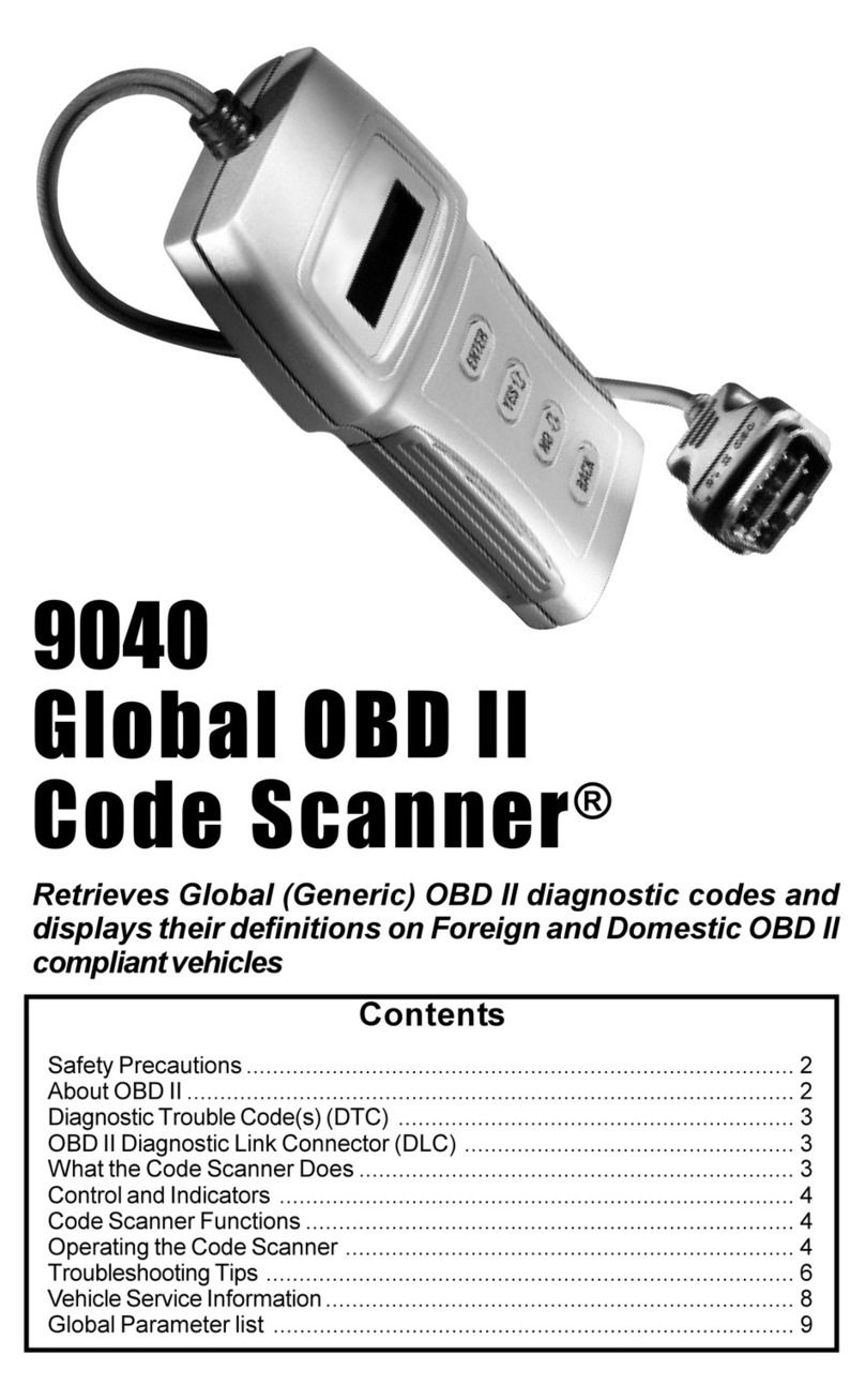
Actron 9040 User manual

Actron
Actron Super AutoScanner CP9145 User manual
