Actronika Tactronik Evaluation Kit User manual

TactronikTM Evaluation Kit - User Manual
TactronikTM
Evaluation Kit
User Manual
TAEKUM0001 – V4.0
1/31

TactronikTM Evaluation Kit - User Manual
Table of Contents
1. Introduction 4
2. Inside the Box 5
3. Quick Start (Evaluation Mode) 6
4. Application Interface 7
4.1. Application Interface: Section Guide 7
4.1.1. Application Interface: Section Explanations 7
4.2. How To: Save or delete a haptic effect with a new user preset 9
4.3. How To: Import an effect database 10
4.3.1. How To: Merge an imported effect database 10
5. Evaluation Board 11
5.1. View of TactronikTM Board 11
5.1.1. Arduino Section 12
5.1.2. TactronikTM Section 13
5.2. Configuration 13
5.2.1. Serial Switch 13
5.3. Power Supply 14
5.4. Connection 15
5.4.1. Micro USB Connections 15
5.4.2. External Sensor Modules 15
5.4.3. Actuators 16
5.5. Debugging 16
5.5.1. Measure Current 16
5.5.2. Signal Debugging 17
5.6. Studied Enough? Go Ahead and Start. 17
5.6.1. Connect TactronikTM to PC with/without Sensor Module 17
5.6.2. Connect Using your Own Application 18
6. External Sensor Modules 18
6.1. Force Sensor Module 18
6.2. Trackpad Module 19
7. Actuator Characteristics 20
7.1. Technical Characteristics & Figures 20
7.2. Performance Graphs 21
8. TactronikTM Module 23
TAEKUM0001 – V4.0
2/31

TactronikTM Evaluation Kit - User Manual
8.1. Mechanical Dimensions 23
9. Troubleshooting 24
10. License and Terms of Use 25
11. Annexe and Advanced Information 28
12.1. How to export an effect database 28
12.2. GPIO (General Purpose Input-Output) Details 29
12.3. Power Supply Jumper 30
12. Revision History 31
TAEKUM0001 – V4.0
3/31

TactronikTM Evaluation Kit - User Manual
1. Introduction
Welcome to the world of HD haptics. The evaluation board will allow you to explore, create and
test new ways of interaction by using haptic stimulation effects. Actronika continues to develop
an entire value chain in order to deliver the highest-end haptics to our clients.
What are the key ingredients of HD haptics?
HD Haptic Effects Library
Our library is based on over 30 years of research in the haptic domaine, including fields like
vibrotactile feedback, neuroscience and tribology (the study of interacting surfaces). It gives full
access to an exclusive collection of HD haptic effects that are all available on the TactronikTM module.
It can easily be upgraded with a new effect based on your project’s needs.
Electronic Driver
The electronic driver is easy to integrate and delivers a reliable performance. It can control up to 200
actuators independently. The 32-bit ARM CortexTM M4f CPU on board along with UART, SPI, PDM and
I2C communication protocols provide more than enough computing power and integration flexibility in
an extremely small package.
Actuators
This actuator has been specifically designed for haptic effects. Its most important parameter is its
large bandwidth, allowing you to produce highly complex effects. It has been optimized and
packaged in a small volume which provides the best volume-to-power ratio delivered on the market.
TAEKUM0001 – V4.0
4/31

TactronikTM Evaluation Kit - User Manual
2. Inside the Box
What will you find inside the Evaluation kit box ?
TAEKUM0001 – V4.0
5/31

TactronikTM Evaluation Kit - User Manual
3. Quick Start (Evaluation Mode)
Once you have opened the box, simply follow these steps (detailed instructions to follow):
1. Download our TactronikTM desktop application file (version 0.18.0) from:
http://dev.actronika.com/resources.html.
2. Install the application on your PC (Windows or Linux OS).
3. Connect the Evaluation kit motherboard to your PC using a USB cable.
4. Connect the power supply (DC 12V) to the motherboard.
5. Launch the application.
6. Choose a serial communication port from the header of the application. (See image below.)
7. Choose a haptic effect to be activated.
8. Choose a preset.
9. Connect a corresponding sensor module that works with the selected effect.
10. Click the Activate button and play with it!
Tips !
●You can deactivate the effect at any time by pressing the Deactivate button .
●At any time you can modify the effect by changing parameters and clicking the Update
button .
●To make sure that the USB communication has been established properly, verify that the
USB icon in the upper right corner is green.
TAEKUM0001 – V4.0
6/31

TactronikTM Evaluation Kit - User Manual
4. Application Interface
4.1. Application Interface: Section Guide
Download our TactronikTM desktop application file (version 0.18.0) from:
http://dev.actronika.com/resources.html.
Once installed and launched, it will appear on your screen as shown below
. This section of the
user manual will explain to you how to use it and what features it provides.
4.1.1. Application Interface: Section Explanations
A. Header
a. Serial port - the name of the serial port connected to the evaluation board.
b. USB connection icon - an indicator of a connection state between the
evaluation board and a PC; connected (green) / disconnected (red)
B. Library Column
a. Filters - a set of words which allow you to find the best matching effects.
Filter selection criteria:
i. Application
ii. Sensors
iii. Number of actuators
iv. Filter by name
TAEKUM0001 – V4.0
7/31

TactronikTM Evaluation Kit - User Manual
b. Library of Effects - a list of available effects on the TactronikTM platform
C. Presets Column - a suggested combination of parameters. Each preset has one of
two possible tags:
i. “Actronika” tag - when a preset was set by us
ii. “User” tag - when a preset is saved by the client
D. Effect Zone
a. Effect description
b. Configuration
c. Parameters - a set of parameters available to control the specific haptic
effects. These parameters change depending on the chosen effect.
Tips !
●Every time you change a default or preset parameter, you must click the Upload button to
be able to experience it.
E. API Zone
a. Activate button - activates communication between the TactronikTM
module and the end module.
b. Deactivate button - deactivates communication between the TactronikTM
module and the end module.
c. Update button - updates parameters of the current activated effect.
d. API frame generator
e. API documentation button - when pressed, this provides easy access to
the API documentation.
Tips !
●When you move the mouse cursor over the specific line in the API frame generator, a
comment will appear to indicate what information it provides to the TactronikTM module.
TAEKUM0001 – V4.0
8/31

TactronikTM Evaluation Kit - User Manual
4.2. How To: Save or delete a haptic effect with a new user preset
The application will automatically suggest to save a new set of parameters under a new name
every time a parameter of an already existing preset is modified. This way, once you tune the
effect the way you like, it will not get lost. All you have to do is click on the icon and give it a
name (See left image below
).
Whenever you want to delete a user-defined effect, just click the delete button in the API
application interface zone (See right image below
).
Name : Delete :
4.3. How To: Import an effect database
You can import a database by clicking on the Menu
button, then on Import
.
Tips !
●Be careful while importing new databases - if you don’t wish for your current database to
be erased to import a new database, see instruction 4.3.1. to learn about merging
imported databases.
TAEKUM0001 – V4.0
9/31

TactronikTM Evaluation Kit - User Manual
4.3.1. How To: Merge an imported effect database
There is also the option to import a new database without deleting the loaded database. This
option will conserve the existing loaded database, and simply add the additional effects of the
new database.
For example:
You have an old database with 2 effects (click and scroll), and 2 effects on a new database (click
and heartbeat). When you use this option, you will now have a new database with 3 effects: click,
scroll, and heartbeat.
To merge 2 databases, click on the Menu
button, then on Import
.
When you select Import
, you will see slider that toggles between Merge Enabled/Merge Not
Enabled
. Select according to your needs.
To finish the procedure, click again on Import
or Merge
.
TAEKUM0001 – V4.0
10/31

TactronikTM Evaluation Kit - User Manual
5. Evaluation Board
5.1. View of TactronikTM Board
TAEKUM0001 – V4.0
11/31

TactronikTM Evaluation Kit - User Manual
5.1.1. Arduino Section
The ISP Port can of the Arduino mega
can be used to flash Arduino mega
with the programmer.
Be careful: If you use this port to flash
Arduino mega, you will erase the
bootloader.
5.1.2. TactronikTM Section
The Tactronik Uart FTDI is to be used with
the serial switch in the middle position (see
section 5.2.1.).
TAEKUM0001 – V4.0
12/31

TactronikTM Evaluation Kit - User Manual
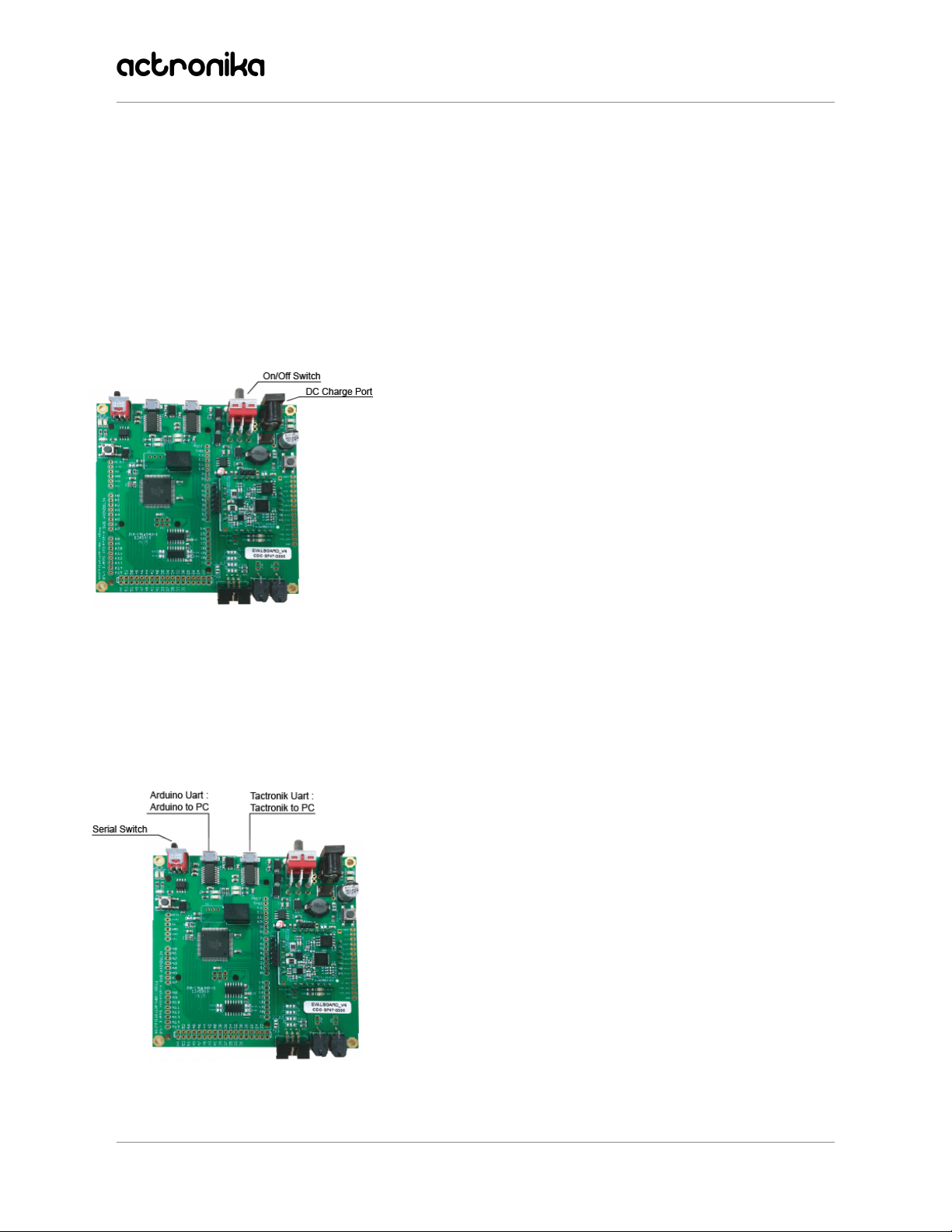
5.2. Configuration
5.2.1. Serial Switch
To configure the Evaluation Board according to your desired use case, there are three
corresponding positions of the serial switch:
1. Evaluation Board
Use the integrated Arduino Mega flash with proxy and the TactronikTM Application Interface demo
kit.
LEFT Serial Switch position - Connect TactronikTM to Arduino, (via the LEFT USB port).
2. Development Board
Use the integrated Arduino and Arduino Shield (display and keypad, or touchscreen).
RIGHT Serial Switch position - Connect TactronikTM to the PC, (connected to FTDI via the RIGHT
USB port) and have direct access. In this mode, you can connect directly by using the FTDI pins.
3. Demo Board (Advanced option
)
Use the integrated Arduino Mega, connected to TactronikTM.
MIDDLE Serial Switch position - without using the micro USB port, connect to FTDI pins for
direct access.
TAEKUM0001 – V4.0
13/31
TactronikTM Evaluation Kit - User Manual
Tips !
●The two Serial Switch LEDs indicate which of the three modes is enabled.
○If LED ‘ARD’ (left) is on, TactronikTM Is connected to Arduino via the left USB port.
○If LED ‘PC’ (right) is on, TactronikTM Is connected to the FTDI via the right USB port,
which connects TactronikTM directly to the PC.
○If all LEDs are off, TactronikTM Is disconnected.
5.3. Power Supply
To power the board, connect the 12V power supply plug to
the 2.1mm connector.
The large switch on the right-hand side of the motherboard
is the On/Off power switch.
5.4. Connection
5.4.1. Micro USB Connections
There are two micro USB connections:
●The connector on the left is to connect Arduino mega
to the PC, using the serial switch in the left position.
●The connector on the right is to connect TactronikTM
to the PC, using the serial switch in the right position.
TAEKUM0001 – V4.0
14/31

TactronikTM Evaluation Kit - User Manual
5.4.2. External Sensor Modules
This is the plug to connect the external sensor modules.
You can connect Actronika’s provided external modules, or
your own - the use is flexible. You can use this connector to
connect to your own sensor if you set your program on
Arduino.
This connector has :
●2 ADC
●12C
●Power Supply (GND and 3.3V)
5.4.3. Actuators
To connect the actuators to the
Evaluation Kit, you can use:
1. Molex connectors
2. Soldering connections. If you
choose to solder, insert the cables in
from the front of the board and
complete the soldering on the back of
the board.
TAEKUM0001 – V4.0
15/31

TactronikTM Evaluation Kit - User Manual
5.5. Debugging
5.5.1. Measure Current
You can measure the consumption of the
actuators.
To do this, measure the voltage of the
‘cur_meas’ Pad and use the following
formula:
I = Vout / 2
5.5.2. Signal Debugging
These pads allow the user to
connect the oscilloscope to many
signals. These signals are
TactronikTM signals only.
TAEKUM0001 – V4.0
16/31

TactronikTM Evaluation Kit - User Manual
5.6. Studied Enough? Go Ahead and Start.
5.6.1. Connect TactronikTM to PC with/without Sensor Module
To connect WITHOUT a sensor module:
1. Set serial switch mode to connect the TactronikTM to the PC (Right position).
2. Connect the TactronikTM to the PC using the right micro USB connection.
3. Use the desktop Application Interface (version 0.18.0) that you have downloaded from
http://dev.actronika.com/resources.html.
4. Launch the effect without the sensor module.
To connect WITH a sensor module:
1. Set serial switch mode to connect Arduino to PC (Left position).
2. Connect the Arduino to the PC using the left micro USB connection.
3. Flash proxy
application on Arduino.
4. Launch the desktop Application Interface (version 0.18.0).
5. Connect your chosen sensor module to the Evaluation kit.
6. Load and play the effects. To do this, use the desktop Application Interface.
5.6.2. Connect Using your Own Application
1. Set serial switch mode to connect Arduino to PC (Left position).
2. Connect the Arduino to the PC using the left micro USB connection.
3. Flash your own application on Arduino.
4. Connect your chosen sensor module to the Evaluation kit.
5. Use Arduino to control the TactronikTM. To do this, use our APIs and read some Arduino
examples on our GitHub.
Have fun!
TAEKUM0001 – V4.0
17/31

TactronikTM Evaluation Kit - User Manual
6. External Sensor Modules
In the Evaluation mode, three modules are provided so that you can discover and understand the
haptic effects that are associated with our sensors: A Force Sensor module and a Trackpad
module. They are to be connected to the motherboard via the module connector (detailed in
section 5.4.2.).
6.1. Force Sensor Module
Composition
The Force Sensor module consists of:
- Frame
- One actuator
- Connectors (2 Molex, 1 IDC)
- Control Card
- Force Sensor
The module must be connected to the motherboard with
IDC ribbon cable and two Molex Cables.
Use
Once you implement the desired effect through Actronika’s software application, the module can
be used.
●Force Click: Hold the module so that your thumb is on top of the force sensor (circular
section). Press down in order to feel the effect.
●Double Force Click: Same procedure as Force Click. When you feel the first click, apply
more force to feel a second click effect. When you release the pressure, you will feel
again the two clicks release.
TAEKUM0001 – V4.0
18/31

TactronikTM Evaluation Kit - User Manual
6.2. Trackpad Module
Composition
The Trackpad module consists of:
- Frame
- One actuator
- Connectors (2 Molex, 1 IDC)
- Control Card
- Touch surface
The module must be connected to the
motherboard with IDC ribbon cable and two
Molex Cables.
Use
Once you implement the desired effect through Actronika’s software application, the module can
be used.
●Generic Texture (X-axis): Slide your finger from left to right and vice versa to feel the
effect.
●Scroll (Y-axis): Slide your finger from top to bottom and vice versa to feel the effect.
TAEKUM0001 – V4.0
19/31

TactronikTM Evaluation Kit - User Manual
7. Actuator Characteristics
7.1. Technical Characteristics & Figures
Performance Characteristics
Resonant Frequency
65 Hz (±10%)
Bandwidth
10 Hz to 7 kHz1
Acceleration peak-to-peak2
4 g
Consumption RMS2
40 mA
Actuator Characteristics
Dimensions
9.5 x 9.5 x 32 ± 0,1 mm
Total Mass
8,2 ± 0,1 gr
Moving Mass
4,5 ± 0,1 gr
Resistance
4,7 Ω
Inductance
120 µH
Thermal Resistance
30,7 °C/W
Max. Instant Power
5 W
Max. Continuous Power
2 W
Max. Operating voltage
12 Vpp
1 98% of the haptic bandwidth and most of the audio bandwidth
2 At the resonant frequency, a test load of 100 g and an operating voltage RMS of 0,71 V
TAEKUM0001 – V4.0
20/31
Table of contents


