Ublox EVK-M8U User manual

EVK-M8U - User guide
UBX-15023994 - R06 Page 2 of 29
C1-Public Document information
Document information
Title
EVK-M8U
Subtitle
Evaluation kit
Document type
User guide
Document number
UBX-15023994
Revision and date
R06
8-Aug-2020
Disclosure Restriction
C1-Public
Product status
Corresponding content status
In development /
Prototype
Objective specification
Target values. Revised and supplementary data will be published later.
Engineering sample
Advance information
Data based on early testing. Revised and supplementary data will be published later.
Initial production
Early production information
Data from product verification. Revised and supplementary data may be published later.
Mass production /
End of life
Production information
Document contains the final product specification.
This document applies to the following products:
Product name
Type number
Hardware version
Firmware version
PCN reference
Product status
EVK-M8U
EVK-M8U-0-12
D
Flash FW 3.01
UDR 1.31 M8U
N/A
Production
information
European Union regulatory compliance
EVK-M8U complies with all relevant requirements for RED 2014/53/EU. The EVK-M8U Declaration of Conformity (DoC) is
available at www.u-blox.com within Support > Product resources > Conformity Declaration.
u-blox or third parties may hold intellectual property rights in the products, names, logos and designs included in this
document. Copying, reproduction, modification or disclosure to third parties of this document or any part thereof is only
permitted with the express written permission of u-blox.
The information contained herein is provided “as is” and u-blox assumes no liability for its use. No warranty, either express or
implied, is given, including but not limited to, with respect to the accuracy, correctness, reliability and fitness for a particular
purpose of the information. This document may be revised by u-blox at any time without notice. For the most recent
documents, visit www.u-blox.com.
Copyright © u-blox AG.

EVK-M8U - User guide
UBX-15023994 - R06 Page 3 of 29
C1-Public Contents
Contents
Document information................................................................................................................................2
Contents ..........................................................................................................................................................3
1Product description ..............................................................................................................................5
1.1 Overview........................................................................................................................................................5
1.2 Kit includes ................................................................................................................................................... 5
1.3 Evaluation software.................................................................................................................................... 5
1.4 System requirements ................................................................................................................................ 5
2Specifications .........................................................................................................................................6
2.1 Safety precautions ..................................................................................................................................... 6
3Device description.................................................................................................................................7
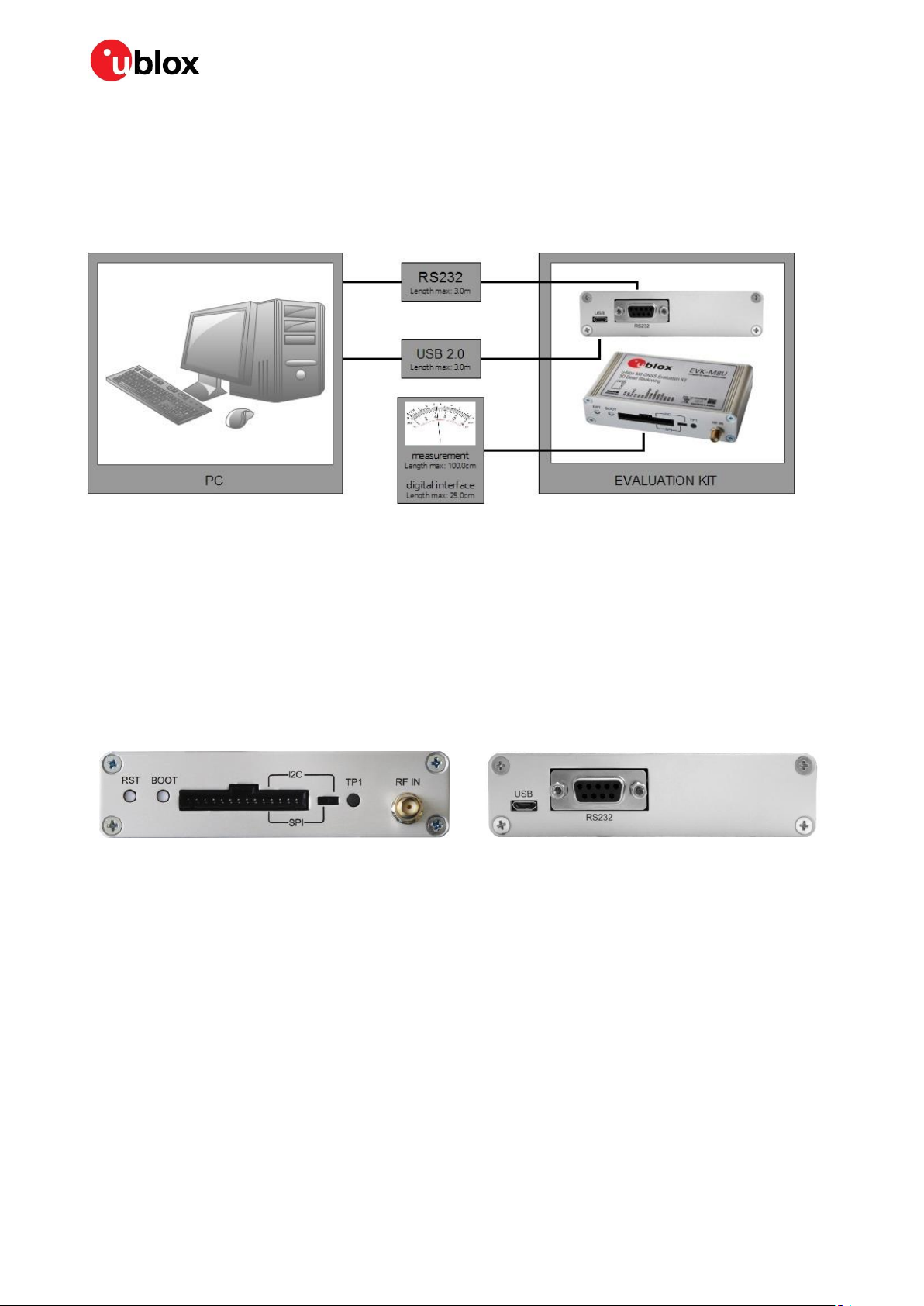
3.1 Interface connection and measurement................................................................................................7
3.2 Active antenna............................................................................................................................................. 7
3.3 Evaluation unit.............................................................................................................................................7
3.3.1 Antenna connector............................................................................................................................. 7
3.3.2 USB ........................................................................................................................................................8
3.3.3 UART .....................................................................................................................................................8
3.3.4 RST button........................................................................................................................................... 8
3.3.5 Safeboot button..................................................................................................................................8
3.3.6 Slide switch .......................................................................................................................................... 8
3.3.7 Front test connector ..........................................................................................................................9
3.3.8 LED.......................................................................................................................................................10
3.3.9 Backup battery ..................................................................................................................................10
3.3.10 GNSS configuration .........................................................................................................................10
4Setting up.............................................................................................................................................. 11
4.1 EVK-M8U installation...............................................................................................................................11
4.1.1 Mounting the GNSS antenna .........................................................................................................11
4.1.2 Mounting the EVK-M8U ..................................................................................................................11
4.1.3 Connecting the cables .....................................................................................................................12
4.2 Recommended configuration .................................................................................................................12
4.2.1 Serial port default configuration ...................................................................................................12
4.2.2 UDR configuration ............................................................................................................................12
4.3 UDR operation............................................................................................................................................14
4.4 Accelerated initialization and calibration procedure .........................................................................16
5Test drives ............................................................................................................................................ 17
6Measuring tracking current ............................................................................................................ 18
7Block diagram ...................................................................................................................................... 19
8Board layout.......................................................................................................................................... 20
9Schematic ............................................................................................................................................. 23
10 Battery replacement ......................................................................................................................... 24
11 Troubleshooting.................................................................................................................................. 25

EVK-M8U - User guide
UBX-15023994 - R06 Page 4 of 29
C1-Public Contents
12 Common evaluation pitfalls ............................................................................................................ 27
Related documents ................................................................................................................................... 28
Revision history.......................................................................................................................................... 28
Contact.......................................................................................................................................................... 29

EVK-M8U - User guide
UBX-15023994 - R06 Product description Page 5 of 29
C1-Public
1Product description
1.1 Overview
The EVK-M8U evaluation kit simplifies the evaluation of the high performance u-blox M8 Untethered
Dead Reckoning positioning products. The built-in USB interface provides both power supply and
high-speed data transfer, and eliminates the need for an external power supply. The u-blox evaluation
kits are compact, and their user-friendly interface and power supply make them ideally suited for use
in laboratories, vehicles and outdoor locations. Furthermore, they can be used with a PDA or a
notebook PC, making them the perfect companion through all stages of design-in projects.
Evaluation kit
Description
Suitable for
EVK-M8U
u-blox M8 Evaluation Kit, 3D UDR with on-board sensors
NEO-M8U, EVA-M8E
Table 1: List of products supported by EVK-M8U evaluation kit
1.2 Kit includes
Evaluation unit
USB cable
Active GPS / GLONASS / BeiDou antenna with 3 m cable
Quick Start card
1.3 Evaluation software
The u-center software installation package for the EVK can be downloaded from www.u-
blox.com/en/evaluation-software-and-tools.
Once the .zip file is downloaded, extract the file contents in the Tools folder and double-click the
extracted .exe file. The software components will be installed in your system and placed under the “u-
blox” folder in the “Start > Programs” menu.
The u-center application is an interactive tool for configuration, testing, visualization and data
analysis of GNSS receivers. It provides useful assistance during all phases of a system integration
project. The latest version of the u-center should be used.
1.4 System requirements
PC with USB interface
Operating system: Windows Vista onwards (x86 and x64 versions)
USB drivers are provided in the evaluation kit installation software

EVK-M8U - User guide
UBX-15023994 - R06 Specifications Page 6 of 29
C1-Public
2Specifications
Parameter
Specification
Serial interfaces
1 USB V2.0
1 RS232, max. baud rate 921.6 kBd
DB9 +/- 12 V level
14 pin –3.3 V logic
1 DDC (I2C compatible) max. 400 kHz
1 SPI –clock signal max. 5.5 MHz –SPI DATA max. 1 Mbit/s
Dimensions
105 x 64 x 26 mm
Timing interface
Timepulse output
Power supply
5V via USB or external powered via extra power supply pin 14 (V5_IN) and common
supply/interface ground pin 13 (GND)
Normal operating temperature
-40 °C to +65 °C
Table 2: EVK-M8U specifications
⚠THE EVK CASE-WORK IS CONNECTED TO THE COMMON SUPPLY/INTERFACE GROUND PIN.
Contact u-blox technical support for assistance if required.
2.1 Safety precautions
EVK-M8U must be supplied by an external limited power source in compliance with clause 2.5 of the
standard IEC 60950-1. In addition to an external limited power source, only separated or Safety Extra-
Low Voltage (SELV) circuits are to be connected to the evaluation kit, including interfaces and
antennas.
☞For more information about SELV circuits, see section 2.2 in the IEC 60950-1 [5] safety standard.
⚠CAUTION! IN THE UNLIKELY EVENT OF A FAILURE IN THE INTERNAL PROTECTION CIRCUITRY
THERE IS A RISK OF EXPLOSION WHEN CHARGING FULLY OR PARTIALLY DISCHARGED
BATTERIES. REPLACE THE BATTERY IF IT NO LONGER HAS SUFFICIENT CHARGE FOR UNIT
OPERATION. CHECK THE BATTERY BEFORE USING IF THE DEVICE HAS NOT BEEN OPERATED
FOR AN EXTENDED PERIOD OF TIME.

EVK-M8U - User guide
UBX-15023994 - R06 Device description Page 7 of 29
C1-Public
3Device description
3.1 Interface connection and measurement
To connect the EVK to a PC, use a standard SUBD-9 cable and the included USB cable. The use of
RS232 and external power supply is optional. USB provides both power and a communication channel.
Figure 1: Connecting the unit for power supply and communication
3.2 Active antenna
The EVK-M8U evaluation kit includes a GPS / Galileo / GLONASS / BeiDou antenna with a 3-meter
cable. It is possible to connect various active and passive GNSS antennas with SMA connectors to the
evaluation unit.
The recommended maximum antenna supply current for active antennas is 30 mA.
3.3 Evaluation unit
Figure 2 shows the front and the rear panel of the EVK-M8U evaluation unit.
Front panel
Rear panel
Figure 2: EVK-M8U evaluation unit –front and rear panels
3.3.1 Antenna connector
An SMA female jack is available on the front side (see Figure 2) of the evaluation unit for connecting
an active or passive antenna. The EVK provides a DC supply at the RF input of 3.3 V for active
antennas. The maximum supported antenna current is 30 mA; internal protection limits the
maximum short circuit current to 60 mA.
To avoid the damage of RF input caused by ESD or electrical overstress, and to seek maximum
consistency and repeatability of performance independently of the RF component used, the EVK-
M8U has an onboard LNA.
⚠The connector is only to be used with a GNSS antenna or simulator. Do not connect this equipment
to cable distribution systems.

EVK-M8U - User guide
UBX-15023994 - R06 Device description Page 8 of 29
C1-Public
3.3.2 USB
A USB V2.0 compatible serial port is featured for data communication and power supply.
3.3.3 UART
The evaluation unit includes an RS232 DCE port for serial communication that is compatible with PC
serial ports.
Connect using a straight RS232 serial cable with male and female connectors to the DTE port on your
PC. The maximum cable length is 3.0 meters. To configure the RS232 port, use the CFG-PRT
command in the u-center application. The maximum operating baud rate is 921.6 kBd.
If you are using a USB to RS232 adaptor cable, you can connect it directly to the evaluation kit RS232
port.
The 9-pin D-SUB female connector is assigned as listed in Table 3:
Pin no.
Assignment
1
not connected
2
TXD, GNSS Transmit Data, serial data to DTE
3
RXD, GNSS Receive Data, serial data from DTE
4
not connected
5
GND
6
not connected
7-9
not connected
Table 3: SUB-D9 connector pin descriptions for the EVK-M8U
3.3.4 RST button
The RST button on the front panel resets the unit. To avoid an inadvertent reset, the button is
recessed.
3.3.5 Safeboot button
This is used to set the unit in safeboot mode. In this mode, the receiver executes only the minimal
functionality, such as updating new firmware into the SQI flash. In order to set the receiver in safeboot
mode, follow these steps.
Press the BOOT button and keep holding it down
Press the RST button
First release the RST button
Then release the BOOT button
If the UART interface needs to be used, the training sequence must be sent to the receiver.
The training sequence is a transmission of two bytes 0x55 55 at the baud rate of 9600 Bd. You
must wait for at least 100 milliseconds before the interface is ready to accept commands.
3.3.6 Slide switch
Use the slide switch on the front panel to choose between I2C (and UART) and SPI communication
ports. You must reset the unit by pressing the RST button when the slide switch has been changed.
1. I2C: With this selection, the EVK operates with the UART (RS232 DB9 –rear panel or the 3.3 V
level TXD (MISO), RXD (MOSI) at the front panel). Also the communication via 3.3 V DDC interface
(I2C) is selected.
2. SPI: With this selection, the EVK operates only with the SPI interface. RS232 (DB9) is switched
off.

EVK-M8U - User guide
UBX-15023994 - R06 Device description Page 9 of 29
C1-Public
3.3.7 Front test connector
This 14-pin connector provides access to additional functionality to the EVK via various interface pins.
The connector also enables measurement of the current used by the EVK. For accurate
measurements, it is recommended to use a maximum of 1-meter cable.
When connecting the 3.3 V digital interfaces, SPI and DDC to your application, a cable length of less
than 25 cm is recommended.
We recommend using the ACE-AM-0 mating connector or equivalent available from our online shop.
All pins are ESD-protected.
Pin no.
Pin name
I/O
Level
Description
14
V5_IN
I
4.75 V –5.25 V
Power input –can be used instead of USB
13
GND
I
-
Common ground pin for case-work, power and serial interface
connections
12
P1A (VCC)
O
3.3 V
Regulated power output/monitor –max. current supply 100 mA
1Ω 1% resistor for over-all current measurement to pin 11 (P1B)
NOTE: This supply powers the active antenna, additional LNA, LED and
UART interface buffers directly.
11
P1B
O
Second connection for module current measurement (see Figure 11)
10
P2A
O
3.0 V
Battery output (unloaded)
100 Ω 1% resistor for battery backup current measurement to pin 9
(P2B)
NOTE: There is a current protection to 3 mA. See circuit in Figure 13
(D2, D4, R29)
9
P2B
O
Second junction for battery backup current measurement
8
TIMEPULSE
O
-
Time pulse (internally buffered output)
7
EXTIN0
I
3.3 V
External interrupt input
6
RESERVED1
-
-
Not connected
5
SDA / CS
I/O
3.3 V
If slide switch is on I2C, the DDC interface is selected; Function: data
input / output
If slide switch is on SPI, the SPI interface is selected; chip select input –
LOW ACTIVE
4
SCL / SCK
I/O
3.3 V
Clock input / output
3
TxD / MISO
I/O
3.3 V
If slide switch is on I2C, the DDC interface is selected / UART TxD (3.3 V
level)
If slide switch is on SPI, the SPI interface is selected; Master in Slave
out (MISO)
2
RxD / MOSI
I/O
3.3 V
If slide switch is on I2C, the DDC interface is selected / UART RxD (3.3 V
level)
If slide switch is on SPI, the SPI interface is selected; Master out Slave in
(MOSI)
1
GND
I
-
Common ground pin
Table 4: Connector pin descriptions for the EVK-M8U (pins numbered from right to left on the front panel)
⚠THE EVK CASE-WORK IS CONNECTED TO THE COMMON SUPPLY/INTERFACE GROUND PIN
(PIN 13). Contact u-blox technical support for assistance if required.

EVK-M8U - User guide
UBX-15023994 - R06 Device description Page 10 of 29
C1-Public
3.3.8 LED
On the front panel of the unit, a single blue LED may be configured to follow the receiver time pulse
signal using the UBX-CFG-TP5 message. The time pulse may be configured so that the LED starts
flashing at one pulse per second during a valid GNSS fix. If there is no GNSS fix, the LED will only be lit,
without flashing. The time pulse is enabled by default in the EVK-M8U.
3.3.9 Backup battery
The evaluation unit includes a backup battery. This is necessary to store calibration and navigation
information between operations and to enable immediate startup in DR mode, and fast acquisition of
GNSS signals.
Battery
Type
Capacity
Operating temperature range
RENATA 3.0 V Li / MnO²
CR2450
540 mA
-40 °C to +85 °C
Table 5: Backup battery for EVK-M8U
If the built-in backup battery runs low or is empty after a long storage period, purchase the battery
described above for replacement (refer to section 10 for battery replacement guidelines).
⚠CAUTION! RISK OF EXPLOSION IF BATTERY IS REPLACED BY AN INCORRECT TYPE. DISPOSE
OF USED BATTERIES ACCORDING TO THE INSTRUCTIONS!
3.3.10 GNSS configuration
The EVK-M8U supports GPS, QZSS, GLONASS, Galileo and BeiDou.
The GNSS to be used can be configured on u-center (View > Messages View > UBX-CFG-GNSS). For
more information, refer to the u-center User Guide [4], and the u-blox 8 / M8 Receiver Description
including Protocol Specification [3].

EVK-M8U - User guide
UBX-15023994 - R06 Setting up Page 11 of 29
C1-Public
4Setting up
4.1 EVK-M8U installation
The EVK-M8U ships with an active GPS / GLONASS / BeiDou magnetic mount antenna with a 3-meter
cable.
The following sections describe the steps required to complete the EVK-M8U hardware installation.
4.1.1 Mounting the GNSS antenna
Attach the antenna to the car; for best performance attach it on the roof as shown in Figure 33. Bring
the antenna cable in through the window or door. Be careful not to damage the antenna cable.
4.1.2 Mounting the EVK-M8U
The EVK-M8U should be firmly attached to the car body so as to avoid any movement or vibration with
respect to the car body. The EVK should not be attached to any ‘live’ (unsprung) part of the vehicle’s
suspension. Often it is enough to use strong double-sided tape or Velcro tape glued to the bottom of
the EVK-M8U casing. If necessary, mounting brackets may be attached using the end-plate retaining
bolts (M3). The EVK must be secured against any change in position and particularly its orientation
with respect to the vehicle frame.
The orientation of the EVK in all three planes must be established accurately either by measurement
or by using the automatic calibration process described in section 4.2.2.1. Dead reckoning
performance will be seriously impaired by errors or changes in the orientation of the EVK.
⚠The EVK case-work, antenna and USB connectors are linked internally to the common
supply/interface ground (pin 13).
☞In order to achieve the best possible performance, the GNSS antenna should be positioned on the
vehicle roof over the EVK. If GNSS antenna is placed at a significant distance from the EVK,
position offsets can be introduced which might affect the accuracy of the navigation solution. In
order to compensate for the position offset advanced configurations can be applied. Contact u-
blox support for more information on advanced configurations.
Figure 33: Example installation of the GNSS antenna and the EVK-M8U

EVK-M8U - User guide
UBX-15023994 - R06 Setting up Page 12 of 29
C1-Public
4.1.3 Connecting the cables
Unless using USB alone, we recommend using the ACE-AM-0 mating connector (available from the u-
blox online shop) because it locks securely to the front test connector. You will need to solder the
necessary I/O cables to signal sources and outputs as specified in Table 6.
1. Connect the finalized cable to the front connector of EVK-M8U.
2. Connect the unit to a PC running Microsoft Windows by
2.1. USB: Connect via USB port or
2.2. UART: Connect via RS232. Set the slide switch to I2C or
2.3. SPI / I2C compliant DDC: Connect corresponding pins (see Table 4 for pin description). Set the
slide switch accordingly to SPI or I2C.
3. Press the RST button after changing the SPI/ I2C switch.
4. The device may be powered either via USB or from a 5 V supply via the V5_IN input on the front.
5. Connect the RF cable of the GNSS antenna to the RF_IN connector.
6. Start the u-center GNSS Evaluation Software and select the corresponding COM port and baud
rate.
7. Refer to the u-center User Guide [4] for more information.
4.2 Recommended configuration
For optimum navigation performance, the recommended navigation rate configuration is as follows:
The default DR/GNSS-fused navigation solution update rate of 1 Hz is recommended. You can set the
navigation update rate with the message UBX-CFG-RATE. (In this mode, navigation rates up to 30 Hz
are also available from the UBX-HNR-PVT message.)
4.2.1 Serial port default configuration
Parameter
Description
Remark
UART Port 1, input
UBX and NMEA protocol at 9600 Bd
UART Port 1, output
UBX and NMEA protocol at 9600 Bd
Only NMEA messages are activated
USB, input
UBX and NMEA protocol
USB, output
UBX and NMEA protocol
Only NMEA messages are activated
Table 6: Default configuration
4.2.2 UDR configuration
By default, the EVK-M8U is ready to operate in UDR navigation mode. The following sections describe
how to configure the parameters specific to the installation.
4.2.2.1 Sensor/IMU mount angles configuration
Dead reckoning performance relies on accurate configuration of the sensor mount configuration
angles. The angles may be measured and configured manually or established using the Automatic
IMU-mount Alignment feature described below. In either case the configuration is made using
message UBX-CFG-ESFALG.
If you do not know or are not completely certain how to measure the Sensor-mount Misalignment
Angles correctly, enable the Automatic IMU-mount Alignment (see below). Click the Send button after
selecting the “Automatic IMU-mount Alignment” box. The correct angles will then be determined
automatically in Phase II of the calibration drive (see section 4.4).

EVK-M8U - User guide
UBX-15023994 - R06 Setting up Page 13 of 29
C1-Public
Figure 4: u-center showing how to enable Automatic IMU-mount Alignment with UBX-CFG-ESFALG
If you know the IMU-mount Misalignment Angles, enter those values into the UBX-CFG-ESFALG
dialog shown in Figure 4. Make sure the “Automatic IMU-mount Alignment” is unselected. Click the
Send button. For more information, refer to the u-blox 8 / u-blox M8 Receiver Description including
Protocol Specification [3].
☞Automatically determined IMU-mount Alignment angles do not survive a cold start (either by
command or loss of the battery backup supply). If it is important that automatically determined
angles continue to be used after the next cold start, follow the procedure in section 4.2.2.2.
☞If the user reverts to factory defaults with UBX-CFG-CFG command, the UBX-CFG-ESFALG with
correct configuration values (yaw, pitch, roll) shall be issued again. For example, in the basic use
case when the EVK-M8U is mounted flat (label side up) and X-axis on the label is pointing forward,
the user should configure it in UBX-CFG-ESFALG as (yaw, pitch, roll) = (0,0,0).
4.2.2.2 Saving the configuration permanently
If, for example, automatically determined IMU mount angles should be used after the next cold start,
they can be saved in the receiver’s non-volatile memory and will be re-used until the automatic
alignment feature is next enabled. Proceed as follows:
When configuration is indicated as completed in the UBX-ESF-STATUS and UBX-ESF-ALG
windows, copy the angles from UBX-ESF-ALG display to the UBX-CFG-ESFALG dialog. Unselect
the “Automatic IMU-mount Alignment” in UBX-CFG-ESFALG dialog and click the Send button.
Save the configuration as described below.
The entire current configuration of the receiver (including configuration data and all UDR parameters)
can be saved to BBR and non-volatile memory (flash) by sending UBX-CFG-CFG command (see Figure
5 below).

EVK-M8U - User guide
UBX-15023994 - R06 Setting up Page 14 of 29
C1-Public
Figure 5: u-center showing how to save current configuration with UBX-CFG-CFG
4.3 UDR operation
The sections below describes the UDR operation modes.
4.3.1.1 Initialization mode
The purpose of the Initialization phase is to estimate all unknown parameters which are required for
achieving fusion. Note that the initialization phase requires good GNSS signals conditions as well as
periods during which the vehicle is stationary and when it is moving (including turns). Once all of the
required initialization steps are achieved, fusion mode is triggered and the calibration phase begins.

EVK-M8U - User guide
UBX-15023994 - R06 Setting up Page 15 of 29
C1-Public
Figure 6: Screenshot of u-center showing the INITIALIZING mode in UBX-ESF-STATUS message
4.3.1.2 Fusion mode
Once the initialization phase is achieved, the receiver enters navigation mode and starts to compute
combined GNSS/Dead-reckoning fixes and to calibrate the sensor required for computing the fused
navigation solution. The sensor calibration status outputs CALIBRATING. As soon as the calibration
has reached a status where optimal fusion performance can be expected, the sensor calibration
status are flagged as CALIBRATED (see Figure 7).
Figure 7: Screenshot of the u-center application showing the sensor calibration status as CALIBRATED

EVK-M8U - User guide
UBX-15023994 - R06 Setting up Page 16 of 29
C1-Public
4.4 Accelerated initialization and calibration procedure
This section describes how to perform fast initialization and calibration of the UDR receiver for
evaluation purposes.
The duration of the initialization phase mostly depends on the quality of the GNSS signals and the
dynamics encountered by the vehicle. An open and flat area, such as an empty open-sky parking area,
provides suitable good conditions. The initialization and calibration drive should contain phases where
the car is stopped for a few minutes (with the engine running), phases where the car is making
ordinary left and right turns, and phases where its speed is above 30 km/h under good GNSS reception
conditions.
☞Note that the calibration status of some used sensors might fall back to CALIBRATING if the
receiver is operated in challenging conditions. In such a case, fused navigation solution uncertainty
increases until optimal conditions are observed again for re-calibrating the sensors.
☞For more information, see the u-blox 8 / M8 Receiver Description including Protocol Specification
[3].

EVK-M8U - User guide
UBX-15023994 - R06 Test drives Page 17 of 29
C1-Public
5Test drives
☞Before testing can be done, make sure that the initialization and calibration have been completed
according to chapter 4.
We recommend recording and archiving the data of your test drives. You can enable additional
debug messages by clicking the Debug button, and then clicking the Record button (see Figure 8).
When prompted to poll for configuration, click Yes (see Figure 9).
Figure 8: The Debug and Record buttons are used for extra messages and debugging / post-analysis
Figure 9: Allow polling and storing of the receiver configuration into a log file

EVK-M8U - User guide
UBX-15023994 - R06 Measuring tracking current Page 18 of 29
C1-Public
6Measuring tracking current
To measure the NEO-M8U module tracking current with the EVK-M8U, follow these steps:
1. Connect a mean reading voltmeter across P1A (VCC) and P1B of the front connector (see Figure
10).
2. Wait 12 minutes to download all of the GNSS orbital data, or download all the Aiding Data via the
AssistNow Online service.
3. Read the voltage (and average if necessary) on the voltmeter and convert to current (1 mV
corresponds to 1 mA).
4. Perform the test with good signals and clear sky views to ensure that the receiver can acquire the
satellite signals.
☞The NEO-M8U module current measurement includes its internal SQI flash, inertial sensor, and
any current delivered to SPI or I2C interface loads.
For more details, see the circuit in Figure 13.
Hirschman
Part no.: 934160100
P1A
(VCC)
P1B
P1B
P1A
(VCC)
Figure 10: Example –tracking current measurement

EVK-M8U - User guide
UBX-15023994 - R06 Block diagram Page 19 of 29
C1-Public
7Block diagram
Figure 11: EVK-M8U block diagram
Other manuals for EVK-M8U
1
Table of contents
Other Ublox Motherboard manuals

Ublox
Ublox EVK-NINA-B3 Series User manual

Ublox
Ublox C099-F9P User manual

Ublox
Ublox EVK-G45 User manual

Ublox
Ublox EVK-NINA-B1 User manual

Ublox
Ublox EVK-M8U User manual

Ublox
Ublox EVK-U201SARA User manual

Ublox
Ublox SARA-N3 Series User manual

Ublox
Ublox EVK-NINA-W101 User manual

Ublox
Ublox EVK-G35 User manual

Ublox
Ublox EVK-M8BZOE User manual

Ublox
Ublox TOBY-L2 series User manual

Ublox
Ublox EVK-M8QSAM User manual

Ublox
Ublox EVK-R41Z User manual

Ublox
Ublox EVK-R6 User manual

Ublox
Ublox XPLR-HPG-1 User manual

Ublox
Ublox BMD-34 Series User manual

Ublox
Ublox EVK-F9DR User manual

Ublox
Ublox C099-F9P User manual

Ublox
Ublox EVK-M8GZOE User manual

Ublox
Ublox EVK-L4 User manual