ACU-RITE OO592W User manual

~
l
1r
I
00592W INST1129-07
Deluxe Wireless
Weather Station
& Atomic Clock
□:§ I MODEL OO592W
tMain Unit
I t
I
!1�:
I 15� with low
U►RITE.
0
Wireless Sensor
Deluxe Wireless Weather Station
& Atomic Clock
1 CHECK PACKAGE CONTENTS
*dimensions approximate
2 READ

• •
3 INSTALL BATTERIES
Main Unit: Always install batteries into the main unit first. Onthe back of the unit,
remove the battery compartment cover. Insert 2 "AA" alkaline (or lithium - See NOTES
below) batteries. Replacethe cover.
Wireless Sensor: After batteries have been put into the main unit, remove the back
cover of the wireless sensor. Insert 2 "AA" alkaline (or lithium) batteries. Pressthe "TX"
button and replace the back cover of the sensor.Put the sensor aside for now, and
continue to learn about the main unit. Later, in part 5 of this manual you'll learn more
about the wireless sensor.
NOTE: When replacing the batteries for the wireless sensor,remove the batteries from
the sensor and clear the sensor's channel on the main unit by pressing and holding the
CHANNELbutton when the corresponding channel is displayed. Reinstall the batteries
into the wireless sensor and press and release the TX button to synchronize the units.
Operating Range of Batteries Severe cold (below -4° F/-20° C)can cause alkaline
batteries to freeze and function improperly. Use lithium
batteries in extremely low temperature conditions to
ensure continued operation.
Low Battery Indicator:
Whenthe battery level is low for the main unit or the wireless sensor,the
low battery level icons will illuminate.
4 CHOOSE WHERE TO PLACE THE MAIN UNIT and WIRELESS SENSOR
Main Unit: Choose wall mount or table-top placement.
• Choose a location for each unit that is at least 10feet away from other electronic
devices that may interfere with the wireless signal.
• Wall mounting: Usethe mounting slot on the back of the unit to hang it from one of the
supplied screws.
• Table-top placement: Attach the removeable table stand by inserting the two prongs
into the slots at the bottom of the main unit.
Wireless Sensor: When placing the sensor,consider these things:
• Although the sensor is designed for outdoor use,placement in a protected area will
prolong its life.
• Mounting: Usethe mounting slot on the back of the unit to hang it from one of the
supplied screws.
• The sensor must be within 100 feet (30 meters) of the main unit.
• The sensor is resistant to weather and to water. It is NOTWATERPROOF.
• Prolonged exposure to cold weather may cause damage to the LCDpanel.
• Wireless sensor can be placed outdoors to observe outdoor temperatures and
humidity.
2
'
Main Unit
BACK • •
t t
REMOVABLE TABLE STAND
Remove Battery
Compartment Cover
AA C} TX C/FMOOE12 3
• 0 0 0 IL:] •
•
'--:c-----.,A[-':.,a,,' AA
, ' 11
, ------1
,
/ I , AA
, --~--..-~--...
,
,
©' / © ,,~----~ = • •
REMOVE4 SCREWS ' INSTALL
TOOPENBATTERY 1----- 2 "AA"
a COMPARTMENT BATTERIES
✓
\.
© ©
Placement
100 feet maximum
3

5 PREVIEW THE DISPLAYS 6 UNDERSTAND WHAT THE BUTTONS DO
, ',/ ',/ '1/ PRESS & HOLD ',
snooze / light BUTTON NAME PRESS & RELEASE FOR 3 SECONDS
l·Hiidi choose channel 1,2, clears the current
CH(CHANNEL) or 3 channel
Minimum/
Maximum
Indoor memory
-mode
Temperature indicators
& Humidity
l
□
:§
Wireless
Outdoor 32% sensor
Temperature channel
& Humidity Number
-,1s:2t
Y8%t Trend
indicators
Month/Date/Day ~/E••w•~ ..
=~::~~~
Moon Phase -e»DDO0di Antenna is
receiving the
Alarm has time & date
! 121Jl1~
been set signal
g--
Low Battery
Indicators Function
buttons
(Wireless Sensor Display )
Pressthe "MODE" button inside the back of the wireless sensorto display temperature
and/or humidity in one of three ways:
1)Temperaturecontinuously,
2)Humidity continuously, or
3)Temperature for 5 seconds,then humidity for 5 seconds
NOTE: The sensor's display setting does not affect the main unit's display.
Channel
(sensor#) press press 1 ,-,,- °F
"mode" "mode" ,~, ,-, 5
\ button button ('\ '- '- •
1 ,-,,- °F • ( '--. (Alternate icon)
oo.s • n
1 ,t-
_ %
Display Mode 1 Display Mode 2 ,_
,- -,
(Temperature) (Humidity)
Display Mode 3
+a
·c:
::::,
C:
"iii
E
CII
.r::.
+a
0
-
~
u
Ill
.c
"C
C:
Ill
I- +a
0
C:
...
z -
CII
:::) .r::.
+a
z C:
0
"C
-
<C
~
::E~
CII
...
Ill
Ill
C:
0
+a
+a
::::,
.c
C:
0
:.:;
Ill
...
CII
a.
0
..
,, c:::
0
U)
z
LLJ
U)
U)
U)
LLJ
...J
LLJ
c:::
3:
'" ./'-.
MEMORY
(min/max)
ALARM
SET f
+l)
- C/f
zone
SNOOZE/ LIGHT
BUTTON NAME
TX
C/f
Mode
CH (1,2or 3)
read maximum &
minimum values for
temperatures, N/A
humidity (both
indoor &outdoor)
view alarm time for set alarm time
5 seconds
starts radio to set clock &
controlled time calander manually
synchronization
turn alarm on/off
OR fast advance
raise a setting by setting mode
one unit
select 0c or 0 f fast reverse in time
OR setting mode &
lower a setting by current time zone
one unit setting
silence the alarm
for 5 minutes
-or- N/A
activate
backlight for
low-light
viewing
....
PRESS & RELEASE / .......
"
TX C/F MODE
0 0 0 123
sends wireless
~
Ii::]
signal to main unit 1111=
AA C:
select 0c or 0 f
display mode
for wireless sensor C} AA C
11
choose display --
mode for wireless •
sensor 3 buttons &slide
switch Inside BACK
choose channel 1,2, of remote sensor
or 3 case
./ '- .J\..
(alternating temp. & Humidity)
4 5

7 MAIN UNIT FEATURES
Radio-controlled Clock : The unit starts synchronizing the clock after the 1stchannel
of the wireless sensor begins to send its information to the main unit. (This is called
registration.) The built-in antenna receives the official time signal from the US
Government's National Institute of Standards and Technology. A microchip translates
the time signal and adjusts the time display for the correct time, and date.
Manually Setting the Time and Date:
1)Pressand hold the "SET" button, and the year display will flash on the screen. Using
the "+" and "-" buttons set the year.When the correct year is entered, press and
release the "SET" button to confirm the setting.
2) Onceyou have confirmed the year, follow the same procedure to set the month, date,
hour, minute, 12or 24-hour time preference, and DST(Daylight Saving Time).
NOTE: Youcannot change any settings manually if the clock is attempting to synchro-
nize. Allow the clock to finish the cycle, and then manual changes can be made if the
clock has not automatically acquired the signal and set itself to the correct time.
Time Zone:
Note: Default setting is Pacific Time. If you live outside of the Pacific Time Zone, you will
need to set your Time Zone using the following procedure:
1)Pressand hold the "- / C/F" button on the front of the clock for three seconds.The
area of the clock where the seconds are usually displayed will be replaced with the letter
for the time zone it is currently set in.
2) If set to the default setting, you will see a flashing letter "P" on the screen after
pressing and holding the "- / C/F" button. Pressand release the"-/ C/F" button until
the letter shown corresponds to your time zone:
P =Pacific M =Mountain C =Central E =Eastern
Once your zone is displayed, there is nothing more you need to do. After about 3
seconds,the seconds will once again be displayed on your clock.
The antenna icon (,) will flash on and off during synchronization. If the icon disap-
pears, this indicates that the radio signal is not available. If you are unable to obtain a
signal after a long period of time, try placing the base unit away from sources of
interference such as computers, televisions, cordless phone bases,and other electronic
items.
Note: The synchronization process can take 24-72 hours.
Celsius/Fahrenheit:
Pressand release the"-" (minus) button. A beep sounds, and the display will change to
either Fahrenheit or Celsius.
6
Moon Phase: • ) DOO Od(
The moon phase will automatically display based on the calender date. The moon phase
display will scroll from left to right, and pausefor about 5 seconds to display the current
moon phase. NOTE:the moon phase will not be correct unless the date and year are
programmed correctly.
(l..!O~T~H~E:!!R~A~D~J~U~S:.!.T!!!M::E:.:.NT.!.:S::...._________________ ___,)
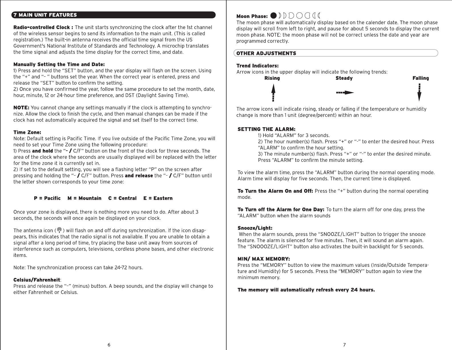
Trend Indicators:
Arrow icons in the upper display will indicate the following trends:
Rising Steady
t
:
•
Falling
•
•
t
The arrow icons will indicate rising, steady or falling if the temperature or humidity
change is more than 1unit (degree/percent) within an hour.
SETTING THE ALARM:
1)Hold "ALARM" for 3 seconds.
2) The hour number(s) flash. Press "+"or"-" to enter the desired hour. Press
"ALARM" to confirm the hour setting.
3) The minute number(s) flash. Press"+" or"-" to enter the desired minute.
Press"ALARM" to confirm the minute setting.
Toview the alarm time, press the "ALARM" button during the normal operating mode.
Alarm time will display for five seconds.Then, the current time is displayed.
To Turn the Alarm On and Off: Pressthe "+" button during the normal operating
mode.
To Turn off the Alarm for One Day: Toturn the alarm off for one day, press the
"ALARM" button when the alarm sounds
Snooze/Light:
Whenthe alarm sounds, press the "SNOOZE/LIGHT" button to trigger the snooze
feature. The alarm is silenced for five minutes. Then, it will sound an alarm again.
The "SNOOOZE/LIGHT" button also activates the built-in backlight for 5 seconds.
MIN/ MAX MEMORY:
Pressthe "MEMORY" button to view the maximum values (Inside/Outside Tempera-
ture and Humidity) for 5 seconds. Pressthe "MEMORY" button again to view the
minimum memory.
The memory will automatically refresh every 24 hours.
7

8 MULTIPLE WIRELESS SENSORS
The main unit supports up to three wireless sensors. Eachadditional wireless sensor
must bedesignated a different channel number.Assigning different channel numbers
differentiate each sensorstemperature and hygrometer readings for the main units'
display.
Addltlonal wireless sensors are sold separately. Call 1·800·556·2548 to order.
WIRELESS SENSOR MODEL :IS01022
1)Openeach sensor by seperating the front and back case.
2) Install batteries, seesection 3.
3) Usethe interior slide switch to select a channel -1, 2, or 3.
4) ChooseCelsiusor Fahrenheit with the C/F button, for the sensor display.
5) With the "MODE" button choose what you want the sensor display to show:
Temperature only,
Humidity only, or
Temperature and humidity, alternating.
6) Pressthe "TX" button to senda signal to the basestation.
7) Snapthe two halves of the casetogather firmly
8) Mount the sensor.Seesection 4 for placement of the wireless sensor unit.
9 PRODUCT SPECIFICATIONS MODELUOO592W
MEASUREMENT RANGE:
Indoormainunit
Outdoor/Indoorhumidity
Wirelesssensor
Channel
Transmission
Resolution
Clock
Batteries
0° Cto+ 50° C(+32°Fto +122°F)
20%-99% RH
-20°Cto +70°C(-4° Fto +158°F)
maximumof threewirelesssensors
upto 30M(100ft.) openarea,RF33MHz
0.1°for temperature,1%for humidity
WWVBradio-controlled,quartzback-up
AAx 2 alkalinefor mainunit;AAx2 alkalinefor
wirelesssensor
8
Do not return product to retail store. For Technical Assistance and
product return Information, please call Customer Care:
877-221-1252
HOURS: Monday through Friday from 8:00 a.m. to 4:45 pm CST.
NOTE:THEMANUFACTURERISNOTRESPONSIBLEFORANYRADIOORTVINTERFERENCECAUSEDBYUNAUTHORIZEDMODIFICATIONSTO
THISEQUIPMENT.SUCHMODIFICATIONSCOULDVOIDTHEUSERAUTHORITYTOOPERATETHEEQUIPMENT
CP- NOTE:ThisequipmenthasbeentestedandfoundtocomplywiththelimitsforaClassBdigitaldevice,pursuanttoPart15ofthe
~
FCCRules.Theselimitsaredesignedtoprovidereasonableprotectionagainstharmfulinterferenceinaresidentialinstallation.This
equipmentgenerates.usesandcanradiateradiofrequencyenergyand,ifnotinstalledandusedinaccordancewiththeinstructions.maycauseharmful
interferencetoradiocommunications.However,thereisnoguaranteethatinterference
willnotoccurinaparticularinstallation.
Ifthisequipmentdoescauseharmfulinterferencetoradioortelevisionreception,whichcanbedeterminedbyturningtheequipmentoffandon.the
userisencouragedtotrytocorrecttheinterferencebyoneormoreofthefollowingmeasures:
--Reorientorrelocatethereceivingantenna.
··Increasetheseparationbetweentheequipmentandreceiver.
--Connecttheequipmentintoanoutletonacircuitdifferentfromthattowhichthereceiverisconnected.
--Consultthedealeroranexperiencedradio/TVtechnicianforhelp.
(71; PLEASEDISPOSEOFOLDORDEFECTIVEBATTERIESINANENVIRONMENTALLY
'p.e1SAFEWAYINACCORDANCEWITHYOURLOCALREGULATIONS
If at anytime inthe future you needto disposeof this product pleasenotethat:
Wasteelectrical productsshouldnot bedisposedtogether with householdwaste.
Pleaserecyclewherefacilities exist.Checkwith your localAuthority or retailer
for recyclingadvice
LIMITED WARRANTY -INTERNATIONAL
Consumer may have more remedies at law than follows. Chaney Instrument Company
warrants to the owner, this product to be free from defect in material and workmanship
for one year from date of purchase. CHANEY INSTRUMENT SHALL NOT BE
LIABLE FOR ANY INCIDENTAL, INDIRECT OR CONSEQUENTIAL DAMAGES,
WHETHER ARISING IN CONTRACT OR TORT. Chaney Instrument's obligation
(at its option) is limited to repair or replace this product. For in-warranty repair, send
product, accompanied by Guarantee, bearing Dealer's name and date of purchase, with
$5.00 to cover handling and postage, to:
www.chaneyinstrument.com
Tel: 877-221-1252
Made in China
9
Chaney Instrument Company
965 Wells Street
Lake Geneva, Wisconsin 53147
Table of contents
Other ACU-RITE Weather Station manuals

ACU-RITE
ACU-RITE 01201 User manual

ACU-RITE
ACU-RITE 01098CDI User manual

ACU-RITE
ACU-RITE 737 User manual

ACU-RITE
ACU-RITE 8575 User manual

ACU-RITE
ACU-RITE 00829 User manual

ACU-RITE
ACU-RITE 00594W User manual

ACU-RITE
ACU-RITE 00502 User manual

ACU-RITE
ACU-RITE 01033W User manual

ACU-RITE
ACU-RITE 02001 User manual

ACU-RITE
ACU-RITE 01531 User manual

ACU-RITE
ACU-RITE 1015 User manual

ACU-RITE
ACU-RITE 1502RX User manual

ACU-RITE
ACU-RITE 06035RM User manual

ACU-RITE
ACU-RITE Atlas User manual

ACU-RITE
ACU-RITE 02099 User manual

ACU-RITE
ACU-RITE 02045W User manual

ACU-RITE
ACU-RITE 02050CAUDI User manual

ACU-RITE
ACU-RITE 06022RM User manual

ACU-RITE
ACU-RITE 01181 User manual

ACU-RITE
ACU-RITE 02010 User manual