Acuity Brands ATRIUS EGW G2 User manual
1 of 4
Edge Gateway (EGW G2)
Acuity Brands | One Lithonia Way Conyers, GA 30012 Phone: 800.535.2465 www.acuitybrands.com © 2020 Acuity Brands Lighting, Inc. All rights reserved. Rev. 01/07/2021
FCC ID: 2ADCB-RMODIT IC: 6715C-RMODIT IFETEL: RCPACRM18-1879 Acuity Brands Lighting Inc. RMODIT
Electrical Specifications Input Ratings 120-277VAC (MVOLT), 120-480VAC (UVOLT)
Maximum Load 20A general purpose, tungsten and standard
ballast; 16A electronic ballast (120-347VAC);
5A general purpose, tungsten and standard
ballast, electronic ballast (480VAC)
Minimum Load None
Mechanical Mounting 1/2” Knockout (7/8” hole)
Connection Type Line and Low Voltage Leads
Environmental Warrantied Operating Temperature -10°C to 60°C up to 5 amps; -10°C to 50°C up
to 20 amps
Standards/ Ratings RoHS, UL 916, FCC / IC / IFETEL
SPECIFICATIONS (EGW)
READ AND FOLLOW ALL SAFETY INSTRUCTIONS!
SAVE THESE INSTRUCTIONS AND DELIVER TO OWNER AFTER INSTALLATION
IMPORTANT SAFEGUARDS
WHEN USING ELECTRICAL EQUIPMENT, BASIC SAFETY PRECAUTIONS SHOULD
ALWAYS BE FOLLOWED INCLUDING THE FOLLOWING:
• DO NOT USE OUTDOORS.
• DO NOT MOUNT NEAR GAS OR ELECTRIC HEATERS.
• EQUIPMENT SHOULD BE MOUNTED IN LOCATIONS AND AT HEIGHTS WHERE
IT WILL NOT READILY BE SUBJECTED TO TAMPERING BY UNAUTHORIZED
PERSONNEL.
• THE USE OF ACCESSORY EQUIPMENTNOT RECOMMENDED BY THE
MANUFACTURER MAY CAUSE AN UNSAFE CONDITION.
TITLE 20/24
√ Do not exceed maximum wattage, ratings, or published
operation conditions of product.
√ Do not overload.
√ Follow all manufacturer’s warnings, recommendations
and restrictions to ensure proper operation of product.
• To reduce the risk of death, personal injury or property damage from fire, electric shock, falling parts, cuts/abrasions,and other hazards please read all warnings and instructions included with and on the fixture box and all fixture labels.
• Before installing, servicing,or performing routine maintenance upon this equipment,follow these general precautions.
• Installation and service should be performed by a qualified licensed electrician.
• Maintenance should be performed by qualified person(s) familiar with the products’ construction & operation & any hazards involved. Regular maintenance programs recommended.
• To be installed to a circuit with overvoltage control to Overvoltage category Cat.III or less, minimum suppression rating 6.0 kV for a 600 V ac rms system voltage
• DO NOT INSTALL DAMAGED PRODUCT! This product has been properly packed so that no parts should have been damaged during transit.Inspect to confirm. Any part damaged or broken during or after assembly should be replaced.
CAUTION: RISK OF PRODUCT DAMAGE
√ Electrostatic Discharge (ESD): ESD can damage product(s). Personal grounding equipment should be worn
during all installation or servicing of the unit.
√ Do not touch individual electrical components, as this can cause ESD and aect product performance.
√ Do not stretch or use cable sets that are too short or are of insucient length.
√ Do not tamper with contacts.
√ Do not modify the product.
√ Do not change or alter internal wiring or installation circuitry.
√ Do not use product for anything other than its intended use.
WARNING - RISK OF BURN or FIRE
CAUTION - RISK OF INJURY
√ Wear gloves and safety glasses at all times when
installing, servicing or performing maintenance.
WARNING - RISK OF ELECTRIC SHOCK
√ Disconnect or turn o power before installation or servicing.
√ Verify that supply voltage is correct by comparing it with the
product information.
√ Make all electrical and grounded connections in accordance with
the National Electrical Code (NEC) and any applicable local code
requirements.
√ All wiring connections should be capped with UL approved
recognized wire connectors.
√ All unused connector openings must be capped.
C US LISTED
WARRANTY
5-year limited warranty.
Full warranty terms located at: www.acuitybrands.com/CustomerResources/Terms_and_conditions.aspx
NOTE: Specications subject to change without notice.
Actual performance may dier as a result of end-user environment and application.
FCC ID: 2ADCB-RMODIT
IC: 6715C-RMODIT
IFETEL: RCPACRM18-1879
Acuity Brands Lighting Inc. RMODIT
This device complies with Part 15 of the FCC Rules. Operation is subject to the following two conditions: (1) This
device may not cause harmful interference, and (2) this device must accept any interference received, including
interference that may cause undesired operation.
Este equipo contiene el módulo con IFT #: RCPRIBM18-1491 La operación de este equipo está sujeta a las
siguientes dos condiciones: (1) es posible que este equipo o dispositivo no cause interferencia perjudicial y (2)
este equipo o dispositivo debe aceptar cualquier interferencia, incluyendo la que pueda causar su operación
no deseada.
NOTE: This equipment has been tested and found to comply with the limits for a Class B digital device, pursuant to part 15 of the FCC Rules. These limits are designed to provide reasonable protection against harmful interference in a
residential installation. This equipment generates, uses and can radiate radio frequency energy and, if not installed and used in accordance with the instructions, may cause harmful interference to radio communications. However, there is no
guarantee that interference will not occur in a particular installation. If this equipment does cause harmful interference to radio or television reception, which can be determined by turning the equipment off and on, the user is encouraged
to try to correct the interference by one or more of the following measures:
1. Reorient or relocate the receiving antenna.
2. Increase the separation between the equipment and receiver.
3. Connect the equipment into an outlet on a circuit different from that to which the receiver is connected.
4. Consult the dealer or an experienced radio/TV technician for help.
Changes or modifications not expressly approved by the party responsible for compliance could void the user’s authority to operate this equipment.
This device contains licence-exempt transmitter(s)/receiver(s) that comply with Innovation, Science and Economic Development Canada’s licence-exempt RSS(s). Operation is subject to the following two conditions:
1. This device may not cause interference.
2. This device must accept any interference, including interference that may cause undesired operation of the device.”
L’émetteur/récepteur exempt de licence contenu dans le présent appareil est conforme aux CNR d’Innovation, Sciences et Développement économique Canada applicables aux appareils radio exempts de licence. L’exploitation est autorisée
aux deux conditions suivantes :
1. L’appareil ne doit pas produire de brouillage;
2. L’appareil doit accepter tout brouillage radioélectrique subi, même si le brouillage est susceptible d’en compromettre le fonctionnement.
2 of 4
Acuity Brands | One Lithonia Way Conyers, GA 30012 Phone: 800.535.2465 www.acuitybrands.com © 2020 Acuity Brands Lighting, Inc. All rights reserved. Rev. 01/07/2021
IS-XXXXXX-001
Edge Gateway G2
Open Ceiling Installation
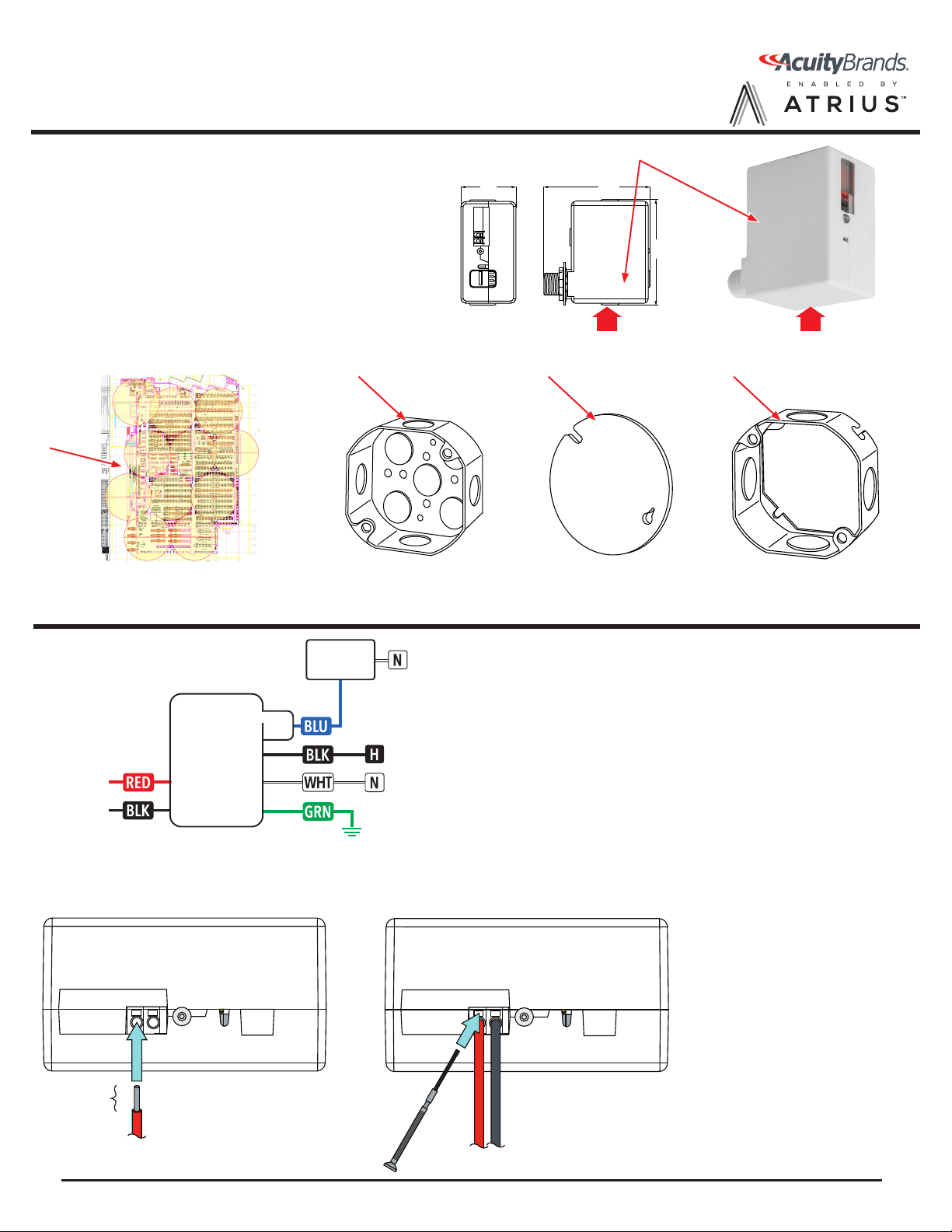
Materials needed (per Edge Gateway install location):
1. Edge Gateway (1)
(Large arrow points to side that MUST face the floor)
2. Edge Gateway Layout (provided) (1)
3. 4" Octagon box (1)
4. 4" Octagon box cover (1)
5. Optional Extension (1)
(use if structure prevents proper orientation)
Edge Gateway G2 Wiring (Do not wire hot)
2
THIS SIDE MUST
FACE FLOOR
THIS SIDE MUST
FACE FLOOR
Strip jacket to correct length, then insert firmly
into terminal hole.
Gently pull to confirm that terminal has
securely captured wirelead.
Strip length: 3/8”
Solid or tinned leads
only
16-20 AWG
Connecting Wire to 24V Terminals
1.
2.
Max screwdriver size: 2mm
Insert precision slotted screwdriver into
terminal slot.
Gently press screwdriver into terminal,
then gently pull wire to remove.
Removing Wire from 24V Terminals
1.
2.
Legend
BLK – Unswitched Hot 120-277VAC or 120-480VAC (UVOLT)
WHT – Neutral
BLU – Switched Output*
RED (Terminal) – +24VDC
BLK (Terminal) – DC Common
GRN – Ground
*Cap off if not used
LOAD
}Normal
+24 VDC
}
USING 24 VDC TERMINAL CONNECTIONS WITH APPROVED ACCESSORIES (OPTIONAL)
1.82”
(UVOLT 1.865”)
3.52”
(UVOLT 4.8”)
3.50”
(UVOLT 4.725”)
1
3 4 5

3 of 4
Acuity Brands | One Lithonia Way Conyers, GA 30012 Phone: 800.535.2465 www.acuitybrands.com © 2020 Acuity Brands Lighting, Inc. All rights reserved. Rev. 01/07/2021
IS-XXXXXX-001
Edge Gateway G2
Drop Ceiling Installation
THIS SIDE MUST
FACE FLOOR
THIS SIDE MUST
FACE FLOOR
1.82”
(UVOLT 1.865”)
3.52”
(UVOLT 4.8”)
3.50”
(UVOLT 4.725”)
1
Materials needed (per Edge Gateway install location):
1. Edge Gateway (1)
(Large arrow points to side that MUST face the floor)
2. Edge Gateway example placement on 60’ centers (1)
3. 4" Octagon box (1)
4. 4" Octagon box cover (1)
5. T Grid Box hanger
2
3
5
4
Edge Gateway G2 Wiring (Do not wire hot)
Strip jacket to correct length, then insert firmly
into terminal hole.
Gently pull to confirm that terminal has
securely captured wirelead.
Strip length: 3/8”
Solid or tinned leads
only
16-20 AWG
Connecting Wire to 24V Terminals
1.
2.
Max screwdriver size: 2mm
Insert precision slotted screwdriver into
terminal slot.
Gently press screwdriver into terminal,
then gently pull wire to remove.
Removing Wire from 24V Terminals
1.
2.
Legend
BLK – Unswitched Hot 120-277VAC or 120-480VAC (UVOLT)
WHT – Neutral
BLU – Switched Output*
RED (Terminal) – +24VDC
BLK (Terminal) – DC Common
GRN – Ground
*Cap off if not used
LOAD
}Normal
+24 VDC
}
USING 24 VDC TERMINAL CONNECTIONS WITH APPROVED ACCESSORIES (OPTIONAL)

4 of 4
Acuity Brands | One Lithonia Way Conyers, GA 30012 Phone: 800.535.2465 www.acuitybrands.com © 2020 Acuity Brands Lighting, Inc. All rights reserved. Rev. 01/07/2021
IS-XXXXXX-001
Edge Gateway G2 Installation
LED Functionality
Installation Steps:
1. Fully install the A1000 AT Fog Gateway, and have it powered on during the EGW installation.
2. Turn power off at circuit breaker for the unswitched circuit that will provide power to the EGW.
3. Install electrical box in accordance with state, local and national electrical codes and requirements.
4. Remove knock out from side of electrical box, that is on the side of the box that has line of sight to the A1000 AT Fog Gateway.
5. Remove retaining nut and washer from EGW mounting nipple.
6. Feed Class 1 wires and mounting nipple through knockout hole, and make connections shown on the previous wiring
diagram. Blue wire should only be connected if the EGW is attached to a light fixture.
7. Rotate EGW such that the small side near the nipple is facing down and is parallel with the floor. See note on previous page
“Materials needed” picture.
8. Install washer and thread retaining nut onto nipple, and hand tighten to wall of electrical box, then apply additional quarter
turn tightening with pliers.
9. Using wire nuts, connect wires as shown in the wiring diagram in accordance to state, local and national codes and
requirements.
10. Install electrical box cover plate before restoring power.
11. 24VDC power terminals connect to optional DC Beacons. See DC Beacon wiring diagrams for additional details.
12. If instructed, place removable sticker on the unit and reference it to the location where the unit is installed.
LED will be ON without blinking if the EGW and all the system components are working properly. Properly working system requires that
the EGW be powered on for 2 hours, the A1000 AT is installed and powered, and an ATG2 asset tag is being carried by the contractor. One
or more blink codes indicate one or more faults are present, or not enough time has elapsed since power up.
1. LED is OFF. Check that black input wire is supplying rated voltage. If rated voltage is supplied EGW is faulty and should be
replaced.
2. Single Blink Code – EGW is faulty and should be replaced.
3. Two Blink Code – A1000 AT has not communicated with the EGW. This code can take up to 2 hours to clear after power on. If code
is not cleared within 2 hours, verify EGW is on the line of sight side to the A1000 AT. If it is not, then rotate the junction box until the
two blink code stops, or verify that the A1000 AT is operating correctly if no EGWs that are on the site are working properly.
4. Three Blink Code – EGW is not receiving BLE messages. Verify that you have an ATG2 tag near the unit. If a tag is present then
EGW is faulty and should be replaced.
5. LED is ON without blinking – System has worked properly since last EGW power cycle.


