Acuity Brands nLight UNITOUCH User manual

NLIGHT®
UNITOUCH
USER MANUAL
2.0

Acuity Brands | One Lithonia Way Conyers, GA 30012 | Phone: 800.535.2465 | www.acuitycontrols.com | © 2019 Acuity Brands Lighting, Inc. | All rights reserved. | Rev. 11/14/2019
Contents
Overview .................................................................................................................................................................................4
Installation ..............................................................................................................................................................................5
Wiring Recommendations ..................................................................................................................................................5
Mounting Instructions ........................................................................................................................................................5
Installation Instructions ......................................................................................................................................................6
Out-of-Box Defaults ................................................................................................................................................................7
User Levels ..............................................................................................................................................................................7
Getting Started........................................................................................................................................................................ 8
Initial Configuration ............................................................................................................................................................8
Logging in as Administrator ................................................................................................................................................9
Logging out of Administrator............................................................................................................................................10
Main Dashboard Screens ......................................................................................................................................................10
Light Control Dashboard.......................................................................................................................................................11
Light Channel Control List.................................................................................................................................................12
Scene Control Dashboard .....................................................................................................................................................13
Activating a Scene.............................................................................................................................................................13
Viewing a Scene ................................................................................................................................................................14
Editing a Scene..................................................................................................................................................................14
Creating a New Scene .......................................................................................................................................................18
Deleting a Scene................................................................................................................................................................19
Shade Control Dashboard.....................................................................................................................................................20
Channel List and Control...................................................................................................................................................21
Hamburger Menu..................................................................................................................................................................22
About.....................................................................................................................................................................................22
Settings..................................................................................................................................................................................23
Display...............................................................................................................................................................................24
Navigation Order...............................................................................................................................................................25
Manage PINs .....................................................................................................................................................................26
Factory Reset ....................................................................................................................................................................27
Technician Mode...................................................................................................................................................................28
Channels............................................................................................................................................................................28
Show/Hide Channels.........................................................................................................................................................31
Inputs ................................................................................................................................................................................32
Outputs .............................................................................................................................................................................34
SensorView............................................................................................................................................................................36
Changing PINs ...................................................................................................................................................................36
Uploading a custom screen saver .....................................................................................................................................37

Acuity Brands | One Lithonia Way Conyers, GA 30012 | Phone: 800.535.2465 | www.acuitycontrols.com | © 2019 Acuity Brands Lighting, Inc. | All rights reserved. | Rev. 11/14/2019
Enabling a channel ............................................................................................................................................................38

Acuity Brands | One Lithonia Way Conyers, GA 30012 | Phone: 800.535.2465 | www.acuitycontrols.com | © 2019 Acuity Brands Lighting, Inc. | All rights reserved. | Rev. 11/14/2019
Overview
The nLight® UNITOUCH is an elegant capacitive touch screen wall switch that leverages the perfect blend between
aesthetic design and intuitive user experience to enable control of any nLight controlled space. Developed with end-
users first in mind, the nLight® UNITOUCH is an easy-to-install wall switch that enables control of nLight-enabled devices,
scenes, shades and channels behind a multi-user access level architecture. The nLight UNITOUCH allows wireless control
using the MyPersonify mobile app through its equipped Bluetooth(R) Low Energy (BLE).
The nLight® UNITOUCH is a multichannel user control device that displays up to 16 individual channels of control
and 16 lighting scenes/shades.
This document covers common configuration and management tasks that arise when setting up and maintaining
the nLight® UNITOUCH as well as step by step instructions for accomplishing various tasks.

Acuity Brands | One Lithonia Way Conyers, GA 30012 | Phone: 800.535.2465 | www.acuitycontrols.com | © 2019 Acuity Brands Lighting, Inc. | All rights reserved. | Rev. 11/14/2019
Installation
The nLight® UNITOUCH is equipped with two RJ-45 ports for CAT5 connection to other nLight-enabled devices as
well as a set of polarity insensitive power terminals for low voltage power.
Wiring Recommendations
A 15-24 VDC or VAC power supply can deliver power to the nLight UNITOUCH via the polarity insensitive terminal
connections on the back of the unit. The PS 150 version power supply (included in the KIT option) is recommended, as it
conveniently mounts through a knock-out on the back of the junction box where the unit is positioned.
Risk of Electric Shock: Turn off power before any kind of servicing to avoid electric shock.
•Comply with all network and power supply guidelines outlined in the Network Guide.
•Use the screws, wall anchors, and wire nuts included for wall mounting and wiring.
•All wiring must comply with electrical wiring diagrams as well as national and local electrical codes.
•We recommend using CAT5 cable to connect the nLight® UNITOUCH to the controller.
Figure 2- Wiring Diagram (Power)
Mounting Instructions
The nLight® UNITOUCH has been designed for ease in installation; However, certain conditions
must apply when choosing a suitable location for the device. These include:
•Install in a location approximately 5 ft (1.5 m) above the floor
•Install approximately 6” (15cm) from a corner in order to provide sufficient access to the
faceplate release tabs.
RJ-45 nLight
Network Ports
Low-Voltage Terminals
(15-24VDC, 40mA)
3.37”
[85.5mm]
0.75”
[19mm]
0.2”
[5mm]
0.83”
[21mm]
0.2”
[5mm]
0.2”
[5mm]
0.28”
[7mm]
0.28”
[7mm]
0.4”
[10mm]
2.20”
[56mm]
2.28”
[58mm]
3.23”
[82mm]
Figure 1- Device Information

Acuity Brands | One Lithonia Way Conyers, GA 30012 | Phone: 800.535.2465 | www.acuitycontrols.com | © 2019 Acuity Brands Lighting, Inc. | All rights reserved. | Rev. 11/14/2019
oAllow for proper clearance around the device’s enclosure and wiring terminals to
provide easy access for hardware configuration and maintenance.
oOrient the device with the ventilation slots towards the top to permit proper heat
dissipation.
•Should not be installed on an exterior wall.
•Should not be installed near a heat source.
•Should not be installed near an air discharge grill.
•Should not be installed in a place where it can be affected by the sun.
•Install in an area that provides proper device ventilation. Nothing must restrain air circulation to
the device.
The nLight® UNITOUCH is not designed for outdoor use.
Installation Instructions
Upon unpacking, inspect the contents of the carton for shipping damages. Do not install a
damaged device.
Take reasonable precautions to prevent electrostatic discharge to the device while installing, servicing or
during operation. Discharge accumulated static electricity by touching one’s hand to a well-grounded object
before working with the device.
For proper installation and subsequent operation of the device, pay special attention to the following
recommendations:
1. Turn circuit breaker to OFF position, or remove fuse(s), and test that power is off before installation process.
Never wire any electrical device with power turned on. Wiring while HOT may cause permanent damage to
this device and other equipment and void warranty.
2. Remove the front cover of the device from the mounting plate:
a. Remove the security screw
b. Using an appropriately sized tool, press in the two (2) release tabs on the sides of the device and
pull the front cover out from the bottom. See Figure 3 for security screw and release tab
locations.
3. Pull all cables 6” (15cm) out of the wall and insert them through the central hole of the back plate.
4. Make sure that the mounting surface is flat and clean.
5. Screw the back plate onto the electrical junction box.
6. Plug the wire(s) into the connector(s). Gently push excess wiring back into the wall.
7. Reattach the front plate and make sure it clips tightly into place. Tighten the security screw.

Acuity Brands | One Lithonia Way Conyers, GA 30012 | Phone: 800.535.2465 | www.acuitycontrols.com | © 2019 Acuity Brands Lighting, Inc. | All rights reserved. | Rev. 11/14/2019
Figure 3- Security Screw and Faceplate Tab Locations
Out-of-Box Defaults
•Screensaver is enabled and the nLight logo is used
•Channels 3-16 are disabled
•Proximity sensor is enabled
•Shade home screen is disabled
•Preset Scenes
oLights On
oLights On –75%
oLights On –50%
oLights On - 25%
oLights Off
User Levels
The nLight UNITOUCH supports two primary user types.
User Type
Description
Administrator
Administrator can access all the features in the device. The administrator only features are
listed below.
•Modify device settings
•Modify Bluetooth settings
•Create/Edit/Delete scenes
•Configure channels
•Configure input/output devices
Basic (Lock-out)
The Basic user privilege allows user to:
1. View and control light channels
2. View and control shade channels
3. Activate and view scenes
4. View product information
Faceplate release tab
Faceplate release
tab
Security screw

Acuity Brands | One Lithonia Way Conyers, GA 30012 | Phone: 800.535.2465 | www.acuitycontrols.com | © 2019 Acuity Brands Lighting, Inc. | All rights reserved. | Rev. 11/14/2019
Getting Started
Upon powering the device out of the factory, users are walked through initial configuration screens to create
administrator PIN, and set up Bluetooth connectivity for the MyPersonify app. While these settings are set during initial
powering, they are configurable through the settings menu as an administrator, or through SensorView.
Initial Configuration
Users are greeted with a welcome, followed by admin PIN creation and confirmation screens. As a standard, all
PINs in the nLight UNITOUCH are to be 6 digits.
Figure 4 - Initial Admin PIN creation process
When PINs are created and confirmed, users are presented with the ability to manage and confirm Bluetooth settings. If
users opt to require Bluetooth PIN entry during device-to-app pairing, they will be walked through the PIN creation
process. Upon completion with Bluetooth, users will be directed to the main Scenes dashboard.

Acuity Brands | One Lithonia Way Conyers, GA 30012 | Phone: 800.535.2465 | www.acuitycontrols.com | © 2019 Acuity Brands Lighting, Inc. | All rights reserved. | Rev. 11/14/2019
Figure 5 - Initial Bluetooth PIN setup process
Logging in as Administrator
The login interface can be accessed through the hamburger menu, and the selection to either navigate to the
“Settings” or “Technician Mode” section (See Figure 6).
NOTE: When logged in as an administrator, all Bluetooth capabilities become disabled until logged back out.

Acuity Brands | One Lithonia Way Conyers, GA 30012 | Phone: 800.535.2465 | www.acuitycontrols.com | © 2019 Acuity Brands Lighting, Inc. | All rights reserved. | Rev. 11/14/2019
Figure 6 - Administrator login workflow
Upon successful login, administrators will be directed to the screen they selected from the hamburger menu.
Logging out of Administrator
Administrators can log out of the unit by tapping on the “Log out” button in the hamburger menu (See Figure 7).
Figure 7- Log out of Administrator mode
Administrators are also logged out when the unit times out and transitions to the screensaver, or when the screen
shuts off due to inactivity.
Main Dashboard Screens
With its ability to allow control of light channels, shade channels and scenes, the nLight UNITOUCH hosts three
main reorganizable navigation screens accessible to all user levels.
Light Control Dashboard
Scene Dashboard
Shade Control Dashboard

Acuity Brands | One Lithonia Way Conyers, GA 30012 | Phone: 800.535.2465 | www.acuitycontrols.com | © 2019 Acuity Brands Lighting, Inc. | All rights reserved. | Rev. 11/14/2019
The light control dashboard allows
users to control devices tracking all
channels of type “Lights”.
It also allows users the ability to
navigate to the channel list screen for
control of other Light channels.
The scene dashboard enables users
the ability to activate scenes and
view more details about the
individual scenes.
This screen also allows administrators
the ability to create new scenes.
The shade control dashboard allows
users the ability to control devices
tracking the first enabled channel of
type “Shades”.
This screen also enables users the
ability to navigate to the channel list
screen for control of other Shade
channels.
Light Control Dashboard
The light control dashboard allows users the ability to control devices tracking channels of type “Light”. By
toggling the control elements in the dashboard screen all channels of type “Lights” receive the inputted control signal.
Home Dashboard Screen
Description
Acuity Brands | One Lithonia Way Conyers, GA 30012 | Phone: 800.535.2465 | www.acuitycontrols.com | © 2019 Acuity Brands Lighting, Inc. | All rights reserved. | Rev. 11/14/2019
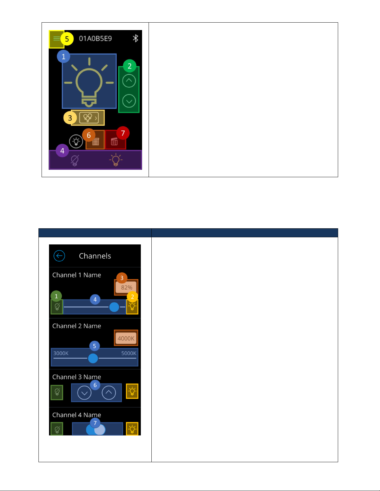
Light Channel Control List
The Light channel control list screen equips users with the ability to individually control light and CCT channels.
Only channels that have been enabled by the Administrator will appear on this screen for control. To enable a channel to
appear on this screen refer to [].
Screen
Description
The following controllable elements enable manipulation of
individual channels. Note that channel control elements
dynamically adjust to the channel control type. (i.e. if “Channel
1” is changed to “On/Off” from “Slider”, the control element will
become a toggle button.
1. Off preset button –Used to toggle lights on channel
“Off”.
2. On preset button –Used to toggle lights on channel
“On”.
3. Precision input Box –Displays the current value of the
positioning of the slider.
a. If tapped, users can enter precise inputs. The
inputs are validated based on range of the
channel setting.
4. Slider control –Used to slide the dim the channel’s light
level.
a. Available only for channels of control type
“Slider”.
5. CCT slider control –Used to slide the kelvin temperature
levels of devices tracking the channel.
a. Available only for channels of control type
“CCT”.
6. Raise/Lower control –Individual buttons used to raise
and lower light levels
a. Exact light levels are not sent when tapping
these control elements, devices tracking these
channels only receive the commands to
From this view, users can control the all the channels of type
“Light”. The screen is equipped with the following controllable
components
1. On/Off preset toggle –Used to toggle lights on and off.
a. When the toggle is transitioned from “Off” to
“On” the light level will dim to the prior dim level
the channel held before turning off.
2. Raise/Lower buttons –Used to dim the intensity level of
devices tracking the light channels.
3. Channel List control –Used to navigate to the channel list
view.
4. Master light channel control –Used to toggle on/off the
first enabled light channel.
5. Hamburger control –Used to display the hamburger
menu.
6. Dashboard navigation control to Shade control
dashboard.
7. Dashboard navigation control to Scene dashboard.

Acuity Brands | One Lithonia Way Conyers, GA 30012 | Phone: 800.535.2465 | www.acuitycontrols.com | © 2019 Acuity Brands Lighting, Inc. | All rights reserved. | Rev. 11/14/2019
raise/lower by a rate of 5%.
b. Available only for channels of control type
“Raise/Lower”
7. On/Off control –Used to toggle on and off devices
tracking the controlled channels.
Scene Control Dashboard
The nLight UNITOUCH allows up to 16 local preset scenes and global scenes. Only local preset scenes can show
more details and are editable.
Figure 8 - Scene Dashboard
Figure 9 - Main Scene Screen logged in as an administrator
Activating a Scene
A scene can be activated by tapping on the targeted scene. Upon tap, activation of the scene will be kicked off
and a visual indicator will be made available by turning the background of the selected scene grey. When the scene has
been fully activated, the background will turn blue. Figure 10 displays the scene activation workflow.
Figure 11 - Activating a scene
Figure 10 - Scene Activation

Acuity Brands | One Lithonia Way Conyers, GA 30012 | Phone: 800.535.2465 | www.acuitycontrols.com | © 2019 Acuity Brands Lighting, Inc. | All rights reserved. | Rev. 11/14/2019
Viewing a Scene
Details of a local preset scene can be viewed by clicking on the buttons highlighted in blue. This action should transition
users to the scene detail screen. Note: Details of global scenes cannot be viewed on the nLight UNITOUCH.
Screen
Description
The detail view of a scene displays light and shade channels
that have been assigned to the scene and their designated
states.
1. Scene Name –Section designated to display the
name of the current scene.
2. Light channel expand/collapse button –Used to
expand and collapse the list of light and CCT channels
configured to be controlled in this scene.
3. Configured light/CCT channel list –Displays light/CCT
channels assigned to this scene and the state
activating the scene will set the lights to.
4. Shade channel expand/collapse button –Used to
expand and collapse the list of shade channels
configured to this scene.
5. Scene Edit button –Button to initiate editing of
current scene. Upon tapping, users will be prompted
to login and edit the scene as administrators.
Editing a Scene
To edit a scene, one must be logged in as an administrator. Refer to the section labeled “Logging in as
Administrator” for login information. From the screen edit screen, Figure 13, administrators can modify the name of a
Figure 12 - Transition from scene list screen into a screen detail

Acuity Brands | One Lithonia Way Conyers, GA 30012 | Phone: 800.535.2465 | www.acuitycontrols.com | © 2019 Acuity Brands Lighting, Inc. | All rights reserved. | Rev. 11/14/2019
scene, assign channels (both light and shade), and edit their states.
Screen
Description
The detail view of a scene displays light and shade
channels that have been assigned to the scene and their
designated states. It also allows administrators the ability
to edit a scene.
1. Scene Name –Input field for the scene name.
From this field, administrators have access to
modify the name of the scene.
a. Maximum 15 characters allowed.
2. Light channel expand/collapse button –Used to
expand and collapse the list of light/CCT channels
configured to this scene.
3. Configured light channel list –Displays light/CCT
channels assigned to this scene and the state
activating the scene will set the levels to.
4. Shade channel expand/collapse button –Used to
expand and collapse the list of shade channels
configured to this scene.
5. Edit button –Transitions to the channel list
screen, where administrators can select channels
to be controlled by the scene and assign the state
the channel should hold.
6. Group control enable/disable button –Used to
determine whether channels under the group will
be controlled when the scene is activated.
a. When set to disabled and the scene is
activated, the assigned channels under
this group will not transition to the state
configured on this scene.
7. Delete button –Used to delete a scene
Figure 13 - Scene detail administrator screen

Acuity Brands | One Lithonia Way Conyers, GA 30012 | Phone: 800.535.2465 | www.acuitycontrols.com | © 2019 Acuity Brands Lighting, Inc. | All rights reserved. | Rev. 11/14/2019

Acuity Brands | One Lithonia Way Conyers, GA 30012 | Phone: 800.535.2465 | www.acuitycontrols.com | © 2019 Acuity Brands Lighting, Inc. | All rights reserved. | Rev. 11/14/2019
Figure 14 - Light channel configuration screen for scenes
The light channel configuration screen for scenes enables
administrators to choose which channels will be
controlled by the scene and configure the channel’s state.
Only channels marked as enabled by administrators,
through the technician mode screen will be affected
(Note that configuration is live –adjusting the control
elements will be reflected in real-time.)
1. Off preset button –Used to toggle “Off” light
channels, while fully expanding shades.
2. On preset button –Used to toggle “On” light
channels, while fully collapsing shades.
3. Channel assignment button –Used to assign and
unassign channels to the scene. Only assigned
channels will be controlled when the channel is
activated.
4. Light level/intensity field –Reflects the light level
of the slider. When tapped, allows administrators
to enter precise light level value. Available only
on channels of control type “Light”.
5. Kelvin Temperature field - Reflects the Kelvin
temperature level of the slider. When tapped,
allows administrators to enter precise level value.
Available only on channels of control type “CCT”.
6. Slider control –Used to slide the dim light
channel’s light level.
7. CCT Slider control –Used to slide the Kelven
temperature level based on CCT range of the
channel.
8. Raise/Lower control –Individual buttons used to
raise and lower light levels
a. Exact light levels are not sent when
tapping these control elements, devices
tracking these channels only receive the
commands to raise/lower by a rate of 5%.
b. Available only for light channels of
control type “Raise/Lower”
9. On/Off control –Used to toggle “On” and “Off”
light channels, while opening and closing shade
channels.

Acuity Brands | One Lithonia Way Conyers, GA 30012 | Phone: 800.535.2465 | www.acuitycontrols.com | © 2019 Acuity Brands Lighting, Inc. | All rights reserved. | Rev. 11/14/2019
Figure 15 - Shade channel configuration screen for scenes
The shade channel configuration screen for scenes
enables administrators to choose which channels will be
controlled by the scene and configure the channel’s state.
Only channels marked as enabled by administrators,
through the technician mode screen will be affected
(Note that configuration is live –adjusting the control
elements will be reflected in real-time.)
1. Close preset button –Used to send command to
fully close devices tracking the channel.
2. Open preset button –Used to send command to
fully open devices tracking the channel.
3. Channel assignment button –Used to assign and
unassign channels to the scene. Only assigned
channels will be controlled when the channel is
activated.
4. Shade level positioning field –Reflects the shade
position of the slider. When tapped, allows
administrators to enter a precise position value.
5. Position slider control –Used to align the shade
channel’s position based on slide value.
6. Raise/Lower control –Individual buttons used to
raise and lower light levels
a. Exact light/shade levels are not sent
when tapping these control elements,
devices tracking these channels only
receive the commands to raise/lower by
a rate of 5%.
b. Available only for light channels of
control type “Raise/Lower”
Creating a New Scene
Scenes are created by administrators through the scene control dashboard. Figure 17 depicts the workflow for
creation of a new scene. Note: You must be logged in as an administrator to gain access to create scenes. Refer to the
section labeled “Logging in as Administrator”for assistance in log in.

Acuity Brands | One Lithonia Way Conyers, GA 30012 | Phone: 800.535.2465 | www.acuitycontrols.com | © 2019 Acuity Brands Lighting, Inc. | All rights reserved. | Rev. 11/14/2019
Deleting a Scene
Scenes can be deleted through accessing their detail views as an administrator.
Figure 16 - Workflow to create a new scene
Figure 17 - Workflow to delete a scene

Acuity Brands | One Lithonia Way Conyers, GA 30012 | Phone: 800.535.2465 | www.acuitycontrols.com | © 2019 Acuity Brands Lighting, Inc. | All rights reserved. | Rev. 11/14/2019
Shade Control Dashboard
The nLight UNITOUCH allows users the ability to dedicate channels as “Shades”. An nLight shade channel operates
like a standard switch channel but contains the label “Shade”. This allows the ability to have a separate set of screens to
control lights and a separate set to control shades. It is important to note that the reference to “shade channels” in
nLight does not equate to that of Fresco. The type of control available to users in the main shade dashboard depends on
the first enabled shade channel’s control type and only allows control of the first enabled shade channel.
Figure 18 - Shade channel home screen
Control Type
Home Screen
Description
Slider
From this view, users can control the first enabled
channel. The screen is equipped with the following
controllable components
1. Position input field –Reflects the shade
position of the slider. When tapped, allows
user to enter a precise position value.
2. Position slider –Used to adjust the position of
the shades tracking the channel to the
selected slide value.
3. Channel List control –Used to navigate to the
channel list view.
4. Master light channel control –Used to toggle
on/off the first enabled light channel.
5. Hamburger control –Used to display the
hamburger menu.
6. Dashboard navigation control to Light control
dashboard.
7. Dashboard navigation control to Scene
dashboard.
Table of contents
Other Acuity Brands Switch manuals


