aculab E1 Use and care manual

Aculab Prosody X PCI Express (PCIe)
Linecard Installation and Replacement
S p a r e P a r t s D o c u m e n t

ii S p a r e P a r t s D o c u m e n t
1081-50817-00 Rev 05 © October 2011
Edition Note
This is the fifth edition of the Aculab®Prosody®-X PCI Express (PCIe) Linecard Installation
and Replacement Spare Parts Document. Information in this document applies to OneBox
systems with version 5.0 SP3 and later.
P/N 1081-50817-00 Rev 05 © October 2011
Copyright Notice
© 2011 Aastra®Technologies Limited. All rights reserved.
This document contains proprietary information, which is protected by copyright.
No part of this document may be reproduced or transmitted in any form or by any means,
electronic or mechanical, including photocopying, recording, or by any information storage
and retrieval system, or translated into another language, without the prior written consent of
Aastra Technologies Limited, Concord, Ontario, Canada.
NOTICE
The information in this document is subject to change without notice.
Aastra MAKES NO WARRANTY OF ANY KIND WITH REGARD TO THIS MATERIAL,
INCLUDING, BUT NOT LIMITED TO, THE IMPLIED WARRANTIES OF
MERCHANTABILITY AND FITNESS FOR A PARTICULAR PURPOSE. Aastra shall not be
liable for errors contained herein, neither for incidental nor for consequential damages in
connection with the furnishing, performance, or use of these materials.
Aastra Technologies Limited
Concord, Ontario, Canada.
Trademarks
Aastra OneBox and Aastra are registered trademarks Aastra Technologies Limited.
Aculab and Prosody are registered trademarks of Aculab Corporation.
Dialogic is a trademark of the Dialogic Corporation.
Windows is a registered trademark of Microsoft Corporation
All other products, brand names, or companies mentioned in this document may be
trademarks or registered trademarks of their respective companies.

S p a r e P a r t s D o c u m e n t i i i
1081-50817-00 Rev 05 © October 2011
Table of Contents
Preface......................................................................................................................................iv
References............................................................................................................................iv
Help.......................................................................................................................................iv
Online Books.........................................................................................................................iv
Document Conventions ..........................................................................................................v
Frequently Used Terms ..........................................................................................................v
Overview................................................................................................................................... 1
Before You Begin................................................................................................................... 1
Planning an E1 or T1 Application............................................................................................ 2
About E1 and T1 ................................................................................................................... 2
About the H.100 Bus ............................................................................................................. 2
About PCI Express (PCIe) Cards .......................................................................................... 2
Technical Specifications of the Prosody X PCIe Linecards .................................................. 3
Installing the Aculab Software ................................................................................................ 4
Installing the Aculab Prosody X PCIe Linecards ................................................................... 5
Confirming the Linecard Identification Number ...................................................................... 5
Installing the Linecard into the Platform................................................................................. 5
Adding the Linecard to Windows Device Manager................................................................. 6
Assigning Network Addresses on the Prosody X card ......................................................... 7
Changing the Network Binding Order on the Telephony Server Platform ..............................10
Configuring the Prosody X Linecard with the Aculab Configuration Tool (ACT) ...............12
Configuring OneBox for the Prosody X linecard ..................................................................15
Cabling Aculab Prosody PCIe Cards to the Telephone System...........................................16

iv S p a r e P a r t s D o c u m e n t
1081-50817-00 Rev 05 © October 2011
Preface
This document is written for Aastra certified OneBox technicians who are experienced with
OneBox and are familiar with its procedures and terminology. This book assumes you are
familiar with OneBox and the Microsoft Windows®operating system.
This installation guide consists of the following parts:
An Overview of the Aculab Prosody X PCI Express linecards
Aculab PCI Express linecard specifications and configurations
Preparing the linecard for service
Preparing the Call Server for service
Installing the linecard
Cabling the linecard to the telephone system
References
Information that is more current may be available from the following sources:
World Wide Web—http://www.aculab.com
The following Aastra documents are available for your reference:
Installing OneBox
Administering OneBox
Removing and Installing Dialogic and Aculab Software Support Components system
installation manual
Help
The primary source of information about OneBox is the online help available within any of its
administrative utilities. You can consult Help by taking one of the following steps:
Click the Help button in the dialog box or window in which you are working
Press the F1 key at any time.
Selecting the Index and Contents tabs from the Help menu causes Help to display an index
system and table of contents that cross-references all OneBox Help files, enabling installers,
and system administrators to pinpoint the information they need with as little time and effort as
possible.
Online Books
Included on the OneBox Telephony Server DVD is a catalog of technical documentation. Refer
to the appropriate technical documentation for additional application and installation information.
Aastra produces technical documentation in Adobe Acrobat PDF format and requires the
Adobe; Acrobat Reader program to view it. You can download the program from
http://www.adobe.com.

S p a r e P a r t s D o c u m e n t v
1081-50817-00 Rev 05 © October 2011
Document Conventions
The following conventions apply to information in this guide:
Bold
Indicates text you type; enter the information exactly as shown. It also
indicates buttons and commands that you click or select from menus.
Italics
Introduce or emphasize a term; can also signify a OneBox voice prompt or
announcement. Titles of other documents are shown in italics as well.
Mono-space
Indicates XML blocks, XML element and attribute names, Parameter names,
structure names, code elements within text, errors, error numbers, and error
strings, PBX commands and programming examples
WARNING A warning paragraph advises you of circumstances that can result in the loss of
data, harm to the telephony server platform, or personal harm.
IMPORTANT An important paragraph gives decision-making information or informs you of the
order in which tasks need to be completed.
NOTE A note gives additional information, provides an explanation, or indicates an exception to
the information in the preceding text.
Frequently Used Terms
The terms System Server and Call Server refer to an organization’s computer platforms that
have OneBox software installed and are dedicated for use as the organizations unified
messaging servers.
The term Telephony Server refers generically to the System Server platform, the Call Server
platform, or both. The term is most often used to describe a software or hardware installation or
configuration practice where the role of the server platform is not specifically expressed


1S p a r e P a r t s D o c u m e n t
1081-50817-00 Rev 05 © October 2011
Overview
This document explains how to install or replace Aculab Prosody X PCI Express E1/T1 High
Capacity Digital Access telephony interface cards, referred to as a Prosody X PCIe linecard, in a
OneBox Call Server platform. The information in this document pertains to platforms running
OneBox version 5.0 SP3 and later.
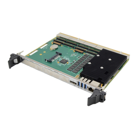
The Aculab Prosody X PCIe linecard is a full media TDM telephony linecard with on-board DSP
that provides call and signaling control of an E1 or T1 telephony interface. It supports a wide
range of signaling protocols including: DPNSS, CAS, and Q.sig. The Prosody X PCIe E1/T1
linecard is used to integrate OneBox with a telephone system using one of these supported
signaling protocols.
Aastra recommends that you read this document in its entirety before beginning the installation
process.
NOTE The information in this document applies to Aculab Prosody X PCI Express, also referred
to as PCIe linecards. For more information on Aculab hardware or software, visit their web site
at http://www.aculab.com.
Before You Begin
Review this section before performing any of the procedures in this document. This section
provides important information about electrostatic discharge and the tools and equipment
required to complete the installation.
Electrostatic Discharge (ESD) Warning
Computer components are extremely sensitive to electrostatic discharge (ESD). You must wear
an anti-static wrist strap and install the linecard at an ESD-safe workstation. Do not open the
static-protective container until necessary. Before removing the linecard from the static-
protective container, touch the container to a grounded, unpainted metal surface for at least two
seconds (this drains the static electricity from the container and from your body). Turn off and
unplug your computer before removing the case.
Gathering Tools and Equipment
Before you begin disassembling the OneBox platform, verify that you have the following
required tools and equipment:
OneBox Telephony Server DVD
One or more Aculab Prosody X PCIe linecards
CTbus cable to connect multiple linecards
One high impedance (120-Ohm) PBX line interface cable with an RJ-45 for each
Prosody X PCIe linecard you are installing. If you are using a 75Ω BNC connection to
the telephone system, you must use a BNC/RJ45 adapter.
License (feature) key to enable the correct number of lines

2S p a r e P a r t s D o c u m e n t
1081-50817-00 Rev 05 © October 2011
Planning an E1 or T1 Application
About E1 and T1
OneBox supports a variety of H.100 bus telephony linecards to implement E1 or T1. Each E1
format carries data at the rate of 2.048 megabits per second, provides 30 voice channels per
span, and is in used in public telephone networks throughout the world (except in North America
and Japan). Each T1 format carries data at the rate of 1.544 megabits per second, provides
either 23 or 24 voice channels per span depending on your configuration. This format is typical
in public telephone networks throughout North America and Japan. E1 and T1 circuits are used
in private networks as well, including computer telephony integrations, around the world. To
implement E1 or T1 successfully using Aculab PCI cards, you must be familiar with the
definitions and guidelines provided in this document.
About the H.100 Bus
To support OneBox, Aastra sells PCIe linecards that exchange data with one another through a
H.100-compliant resource bus. The H.100 standard specifies a hardware design that supports
signals from several earlier resource bus specifications including CTbus, SCbus, MVIP, and
others.
Each telephony linecard in the Call Server platform is equipped with an H.100 connector, to
which a H.100 bus cable is attached, connecting each telephony linecard’s H.100 bus together
through the bus cable. Because the OneBox software is designed to work without terminated
resource buses, it is not necessary to add a terminator pack of any sort to either end of the
H.100 bus cable or to change the termination settings on any H.100 bus linecard in the system.
NOTE The terms CT bus and H.100 are often encountered together. H.100 refers to the specific
variant of the CT bus specification used in PCIe linecards.
About PCI Express (PCIe) Cards
Before you begin, verify that the Call Server platform in which you are installing the linecard is
compatible with the PCIe slot requirement of the Prosody X PCIe card. The Aculab Prosody X
PCIe linecard is a full length x4 form factor PCI Express board that requires 25W of power. The
Prosody X linecard can be installed only in an x4 or greater PCI Express chassis slot. An x4 or
greater slot must be able to support a minimum of 25W per the PCI Express Card
Electromechanical Specification Revision 1.0a or higher.

S p a r e P a r t s D o c u m e n t 3
1081-50817-00 Rev 05 © October 2011
Technical Specifications of the Prosody X
PCIe Linecards
Table 1 lists the technical specifications for the Aculab Prosody X PCIe linecards approved for
use with OneBox.
NOTE Your local telephone company may require some of these specifications. For example, in
the United States, some telephone companies require an FCC registration number if the
linecard is connected directly to central office (CO) lines. Contact your local telephone company
for its requirements.
Table 1: Aculab Prosody X PCIe E1 Technical Specifications
Functionality
Specification
Number of Ports
(Channelization)
1-4 E1/T1 trunks per board 1-30 (E1 channel order)
1-24 (T1 channel order); the correlation between
channelization and OneBox ports is determined by
the linecard identification number.
E1/T1 is software selectable
FCC Registration (USA)
US: STC XD NA N PMXPCIX
Ringer Equivalence (REN)
NAN
USOC Jack Type
RJ45 for E1 or RJ48c for T1
Impedance
Software selectable 75Ω or 120Ω (An RJ45 to BNC
adapter is required for a 75Ω BNC connection)
Cables
BNC or RJ45
Protocols
DPNSS, CAS, Q.sig, T1 (robbed bit)
Physical Features
Description
Board format
Full size single slot
Bus Type
PCIe SIG 1.1 x4 slot
CT Bus
H.100
Power Consumption
25W (x4 lane or greater)
Timing synchronization
On board
Other Equipment (Required if you are
connecting directly to the PSTN)
A CSU is required for T1. A DSU may also be
required depending on the capabilities of the CSU.
The CSU must have an RJ-45 connector to connect
to the Prosody linecard.
Please contact Aculab Technical Support for additional technical specifications, or visit the
Aculab website: http://www.aculab.com.

4S p a r e P a r t s D o c u m e n t
1081-50817-00 Rev 05 © October 2011
Installing the Aculab Software
Aculab software is installed automatically with the OneBox Telephony Server software.
However, you must select the Aculab hardware support component on the Select Hardware
Support Components dialog box during setup.
The software is installed as a hardware support component of the OneBox Server software
found on the Telephony Server DVD. The Aculab software is typically installed at the time of the
initial Call Server software installation. However, if it was not been previously installed, you must
install it by re-installing the OneBox Server software.
If you are upgrading from a previous version of OneBox, you may have to un-install a previous
version of Dialogic® software before you begin the installation. If the OneBox InstallShield
Wizard detects an existing version of Dialogic software during the setup process, the installation
is aborted and you are prompted to un-install all Dialogic software first.
For more information on removing previous versions of Dialogic software, refer to OneBox help
or the system Installation manual, Removing and Installing Dialogic and Aculab Software
Support Components.
IMPORTANT If you are removing Dialogic and Aculab software and you are not installing
another version of Dialogic software, you must re-install OneBox software after you un-install
any previous version of Dialogic software.

S p a r e P a r t s D o c u m e n t 5
1081-50817-00 Rev 05 © October 2011
Installing the Aculab Prosody X PCIe
Linecards
Once the OneBox and Aculab software is installed on the Call Server platform, you can:
Install the linecard(s) into the platform
Configure the IP address of the linecard’s Ethernet port in Windows® Network
Connections
Configure the on-board network IP address in the Aculab Configuration Tool
Complete the configuration of the linecard properties in the Aculab Configuration Tool
Add it to the Boards tab of the System Configuration utility.
Connect the linecard to the telephone system
Confirming the Linecard Identification Number
The serial number of the Prosody X linecard is used to uniquely identify each board installed in
the system. The serial number is located on the upper back edge of the board and has the
format of P/N ACXXXX S/N XXXXXX WONXXX. The six digits following the S/N are used as the
identifier when configuring the linecard.
If your Call Server has more than one installed linecard, make note of the linecard identification
number of each linecard to clarify the process of connecting the ports to the telephone system
later.
Installing the Linecard into the Platform
There are no physical jumpers or switches to set on the Prosody X PCIe linecard. Certain Call
Server platforms may require you to remove the slot retainer bracket from the inside edge of the
linecard before you install it. Remove the two retaining screws that secure it, if necessary.
IMPORTANT Make a note of each linecard serial number before you install the card into the
system. If there are multiple linecards be sure to note which linecard is in each PCIe slot.
To install the Prosody X linecard…
1. Shut down the Call Server services, and then shut down the operating system.
2. Power off the server, and then remove the power cord from the chassis.
3. Locate an appropriate PCIe slot in the Call Server chassis, install each Prosody X PCIe
card, seat it firmly, and then secure it with an end plate clip or screw.
IMPORTANT The PCIe slot you select must be an x4 (4 lane) slot or higher.

6S p a r e P a r t s D o c u m e n t
1081-50817-00 Rev 05 © October 2011
4. Do one of the following:
If the Aculab card you added is …
Then …
The only linecard in the system
An H.100 cable is note required
The first linecard installed in the
platform
Attach the first (end) H.100 Bus connector on
the H.100 Bus cable to the H.100 Bus
connector on the Aculab card.
The connectors on the card and the cable
are designed to fit together in one direction
only.
Neither the first nor last linecard
installed in the platform
Attach the nearest H.100 Bus connector on
the H.100 Bus cable to the H.100 Bus
connector on the first telephony linecard.
The last linecard installed in the
platform
Attach the last (opposite end) H.100 Bus
connector on the H.100 Bus cable to the
H.100 Bus connector on the last telephony
linecard.
IMPORTANT Always connect both ends of the H.100 bus cable to linecards in the
platform. Use the intermediate connectors to connect any intermediate linecards, and
then tuck any unused connectors down between the cards. Leaving an end connector
flagging loose and unused can create interference on the H.100 bus.
Adding the Linecard to Windows Device Manager
Once the Prosody X linecard is installed and the Call Server is restarted, the Windows ―New
Hardware‖ wizard automatically detects the new hardware on startup and adds the appropriate
Aculab device drivers to the Device Manager.
NOTE Windows detects the linecard as an Ethernet Controller.

S p a r e P a r t s D o c u m e n t 7
1081-50817-00 Rev 05 © October 2011
Assigning Network Addresses on the Prosody
X card
The Prosody X PCIe linecard has an onboard dual Ethernet port that services both a network
interface connection and an onboard network switch. You must assign an IP address to both the
network interface connection and the onboard network switch.
NOTE When you have completed this procedure, you may need to re-arrange the binding order
of your network interface cards in the system so that the Prosody X Ethernet ports appear last in
the network binding order. For more information, refer to the section, ―Changing the Network
Binding Order on the Telephony Server Platform.‖
Assign the Prosody X Ethernet addresses to a subnet and TCP/IP address scheme that is
different from that of the current network address scheme of the LAN to which OneBox is
connected. If you have more than one Prosody X card installed, address each one with unique
subnets and IP addresses that do not conflict with the network address scheme of the LAN.
There are two IP addresses per Prosody X card that you must configure; the Network
Connection IP address (Windows Network Connections Configuration), and the on-board
computer IP address of the Prosody X (Aculab Configuration Tool).
IMPORTANT Because network address schemes vary from one company LAN to another,
Aastra can only make recommendations on how to address the Aculab Prosody X linecard.
Ultimately, the decision on what addresses to use is the responsibility of the network
administrator.
An efficient method of providing a new subnet and IP address scheme for the Prosody X
linecards is to use the subnet mask, 255.255.255.252. Two valid IP addresses within the subnet
are XXX.XXX.XXX.1 and XXX.XXX.XXX.2. (The numbers in the fourth or least significant octet
of the IP address are 1 and 2.)
For example, if you have three Prosody X cards installed in the system, all three require
separate TCP/IP addresses that do not conflict with the network address plan of the LAN on
which the Call Server communicates.
Prosody X Card Number 1
Network Connection IP address: 172.40.100.1
Prosody X on-board computer IP address: 172.40.100.2
Subnet Mask 255.255.255.252
Prosody X Card Number 2
Network Connection IP address: 172.40.101.1
Prosody X on-board computer IP address: 172.40.101.2
Subnet Mask 255.255.255.252

8S p a r e P a r t s D o c u m e n t
1081-50817-00 Rev 05 © October 2011
Prosody X Card Number 3
Network Connection IP address: 172.40.102.1
Prosody X on-board computer IP address: 172.40.102.2
Subnet Mask 255.255.255.252
To assign the TCP/IP address of the Network Connection IP Address…
1. Windows 2003 Server - Select Start |Control Panel, and then double-click Network
Connections.
Windows 2008 R2 Server –Select Start | Control Panel | Network Sharing Center,
and then click Change adapter settings.
2. Double-click the Prosody X connection. The Connection Status dialog box displays.

S p a r e P a r t s D o c u m e n t 9
1081-50817-00 Rev 05 © October 2011
3. Windows Server 2003 - Click Properties, and then double-click the Internet Protocol
TCP/IP protocol. The Connection Properties dialog box displays.
Windows Server 2008 R2 - Click Properties, and then double-click the Internet
Protocol Version 4 (TCP/IPv4) protocol. The Connection Properties dialog box
displays.
4. Select the Use the Following IP address radio button, enter a TCP/IP address, subnet
mask, and then click OK.
NOTE If you are using the previous example to create your TCP/IP addresses for the
Prosody X card, enter the address ending in 1 or XXX.XXX.XXX.1, and then the subnet
mask 255.255.255.252 for each of the Prosody X linecards you are installing.
Remember that the third octet (XXX.XXX.XXX.X) of each linecard address must also be
unique.
5. Click OK again, and then click Close to exit the dialog boxes.
6. Close the Network Connections window.

10 S p a r e P a r t s D o c u m e n t
1081-50817-00 Rev 05 © October 2011
Changing the Network Binding Order on the Telephony
Server Platform
OneBox uses the primary (public) network interface card (NIC) in the platform for all network
communications. It must use the first network connection in the network binding order. OneBox
may be a member of two different local or wide area networks (LANs or WANs) or have multiple
network interface cards (NIC) installed and in use for other purposes. You must make sure that
the Prosody X linecard does not interfere with the normal network operation of the Call Server.
Follow the instructions in this section to ensure that the binding order of your network interface
cards is correct. When you install the Prosody X PCI linecard the binding order of the installed
NIC’s should not change, but it is important to note the current binding order before you install
the card, and then check the binding order again once the Prosody X linecard is installed.
Restoring the original binding order should alleviate any problems caused by the change.
NOTE The operating system gives precedence to the first network connection in the list followed
by the remaining connections based on their position in the list.
The following procedure shifts the order of the network connections the NIC provides. To
determine which NIC is associated with a specific network connection, right-click the connection
in the Network Connections window, and then select Properties.
Windows Server 2003
To change the binding order of multiple NICs…
1. Select Start | Settings | Control Panel.
2. In the Control Panel, double-click Network Connections (or Network and Dial-Up
Connections).
3. From the menu bar on the Network Connections window select Advanced, and then
click Advanced Settings.
4. On the Adapters and Bindings tab of Advanced Settings, click the network connection
that serves OneBox.
NOTE The operating system gives precedence to the first connection in the list. It then
assigns priority to the remaining connections based on their positions in the list. The
Prosody X Ethernet linecards must be the last connections in the binding list.
5. Click the up arrow button to the right of the Connections list as many times as needed to
move the primary LAN network connection to the top of the list.
6. Click OK, and then close the Network Connections window and the Control Panel.
7. Restart the Call Server platform if the operating system requires it.
Windows Server 2008 R2
To change the binding order of multiple NICs…
1. From the taskbar, select Start | Settings | Control Panel.
2. In the Control Panel, double-click Network and Sharing Center (use small icons).

S p a r e P a r t s D o c u m e n t 11
1081-50817-00 Rev 05 © October 2011
3. On the left pane, select Change Adapter Settings.
4. Press Alt to display the menu bar.
5. On the menu bar, select Advanced, and then click Advanced Settings.
6. On the Adapters and Bindings tab of Advanced Settings, click the network connection
that serves OneBox.
NOTE The operating system gives precedence to the first connection in the list. It then
assigns priority to the remaining connections based on their positions in the list. The
Prosody X Ethernet linecards must be the last connections in the binding list.
7. Click the up arrow button to the right of the Connections list as many times as needed to
move the connection to the top of the list.
8. Click OK, and then close the Network Connections window and the Control Panel.

12 S p a r e P a r t s D o c u m e n t
1081-50817-00 Rev 05 © October 2011
Configuring the Prosody X Linecard with the
Aculab Configuration Tool (ACT)
Once you have finished assigning the Network Connection address and verified the network
binding order, you can open the Aculab Configuration Tool and finish configuring the Prosody X
card for use with OneBox.
Once the linecard is successfully configured and in service it appears in the Prosody X Page of
the ACT as ―In Service.‖ It also appears in the Card List of the ACT.
The Prosody X linecards do not appear in the Card List view until:
The card is physically installed
The Aculab software is installed correctly
The Aculab Resource Manager and Aculab Startup service are both running
The Prosody X is assigned a TCP/IP address
The Prosody X card is ―In Service‖
To configure the Prosody X linecard with the Aculab Configuration Tool…
1. Select Start, right-click My Computer, and then select Manage.
2. Double-click Service and Applications, and then double-click Services.
3. Verify that the Aculab Resource Manager Service is started. If it is not started, right-click
the Aculab Resource Manager Service, and then select Start.
4. Close the Windows Computer Management window once the service is started.
5. Select Start | All Programs | Aculab |v6 | ACT. The Aculab Configuration Tool displays.

S p a r e P a r t s D o c u m e n t 13
1081-50817-00 Rev 05 © October 2011
6. Click Prosody X. The Prosody X Page displays. If the linecard(s) display with their
corresponding serial numbers, skip to step 9. Otherwise, continue to step 7.
7. Typically, an installed linecard displays on this page with its serial number. If the ACT did
not pre-register the serial number of the card, and the Aculab Resource Manager
Service is running, click Add. The ACT Adding Prosody X Card dialog box displays.
8. Enter the board serial number you previously recorded when you installed the card, and
then skip to step 10.
9. Double-click an individual linecard to open the ACT Editing Prosody X Card dialog box
for that card.
NOTE The linecards display in the order they are assigned within the system. In this
example, the first card with serial number 187959 provides the first telephony ports for
OneBox, and so on.
10. Select the Boot Card box, and then enter callserver as the security key.
11. Enter the TCP/IP address and the subnet mask. If you are using the previous example to
configure the addresses, enter the XXX.XXX.XXX.2 TCP/IP address, and then enter the
subnet mask 255.255.255.252.

14 S p a r e P a r t s D o c u m e n t
1081-50817-00 Rev 05 © October 2011
12. Click Apply, and then click OK to confirm the changes. The linecard initiates a
―Discovery‖ state, and then works its way to the ―In Service‖ state on the Prosody X
Page.
13. Repeat steps 9-12 for each linecard you are installing.
14. From the Views list, click the Card List. Verify that each Prosody X card that reaches the
―In Service‖ state on the Prosody X Page also displays in the Card List.
15. OneBox cannot auto-detect the Prosody X linecard if the card does not reach the ―In
Service‖ state. If the linecard fails to reach the ―In Service‖ state, reboot the server and
allow the system to restart completely before checking the Card List again. If the
linecards fail to go ―In Service‖ after a successful server restart:
16. Verify the Network Connection IP address
17. Verify the ACT configuration is correct for each card
18. Verify that that the two IP addresses assigned to each linecard are on the same subnet
19. Verify the Aculab Resource Manager and Aculab Startup service are both running in the
Windows Service Manager
NOTE Aculab Prosody X PCIe linecards that are configured correctly, yet continuously
fail to reach an ―In Service‖ state, may be indicative of a power resource limitation on the
server platform. For more information, contact Aastra Technical Support.
Other manuals for E1
2
This manual suits for next models
1
Table of contents
