Acumen 51020 Owner's manual


Installation and Wiring
1
The Acumen SCOOTER consists of the following main
components;
• SCOOTER main unit ECU (Electronic Control Unit)
• SCOOTER wiring harness
• 1 x Remote Fob
• Fitting kit including System fuse, spare fuse & Red LED system
indicator
Tool Required:
• Pliers/Cable strippers/Cable cutters
• Drill with 5.5mm and 8mm bits
• Soldering equipment
• Adhesive lines heatshrink tubing
• High quality insulating tape
• Masking tape (for drilling LED hole)
• Multimeter
• General workshop tools
• Scooter wiring diagram
SCOOTER main unit ECU (Electronic Control Unit)
Ensure the fitting of the equipment and the associated wiring does not
affect the operation of the scooter. Be sure the alarm and wiring does not
affect moving parts (such as control cables, brakes) and does not touch
hot parts.
The SCOOTER is designed for scooter use and is fully encapsulated so
water ingress is not of a concern. Likewise, the Key Fob is also of a
waterproof design. We recommend however that the unit is not placed in a
position where it is continually subjected to water and/or pressure
washing.
SSiittiinngg//ppoossiittiioonniinnggtthheeSSCCOOOOTTEERRmmaaiinnuunniitt//EECCUU((EElleeccttrroonniiccCCoonnttrroolluunniitt))
When mounting the unit, use the 5mm screws/nuts supplied in the fitting kit
or cable tie the unit to a suitable frame tube. Take care to mount the unit
where access to it is protected (the more difficult it is to reach, the harder
the job the ‘thief’ has to bypass the alarm).
Route the wiring alongside the scooter wiring, and tape it in the style of the
original scooter wiring.
SSiittiinngg//ppoossiittiioonniinnggtthheeLLEEDDssyysstteemmIInnddiiccaattoorr
Be aware the LED will result in a small increase of electrical current drain.
The LED draws 1mA of electrical current. The LED provides a visual
indication of the alarm’s status, helps with the diagnostic mode of the
alarm, and will warn a potential thief that your scooter is alarmed and that
the alarm is armed.
For this reason, it is preferable to position the LED where it can be easily
seen. Having decided on a suitable position, drill an 8mm hole, pass the
LED through from the back of the hole and then insert the LED into the LED
holder. Then push the LED holder back into the 8mm hole to mount it
securely. Route the LED wires to the position of the SCOOTER ECU.
The alarm has a loom which ends in a 6-way connector. This connector
connects to the wiring loom which is connected to the scooter.

Installation and Wiring
Connect the system wires as
follows:
A larger version of the wiring diagram
can be found on the back page.
The RREEDDwire is the alarm positive feed.
DO NOT connect this directly to the
scooter battery, but connect to the
positive terminal of the starter solenoid.
Use the Red-tagged ring terminal from
the fit kit.
The BBLLAACCKKwire is the alarm negative
connection. Connect this wire to a
suitable earthing point on the scooter
frame. DO NOT connect to the battery
negative terminal. Do NOT connect it to a
sub-frame or fairing-frame. An ideal spot
is the connection of the scooter battery
negative lead & frame. Use the Blue-
tagged ring terminal from the fit kit.
The BBRROOWWNNwire should be connected
to a circuit which becomes live when the
ignition is switched on. Ideally, this
should be connected between the
ignition switch and the scooter fuse box.
If this is not practical, a good place is the
feed to the rear brake light switch.
Acumen recommends this connection is
soldered.
CCoonnnneecctttthhee66--wwaayyccoonnnneeccttoorrssttooggeetthheerr
aannddpprroocceeeeddttooOOppeerraattiioonn
To make the alarm active, you only need to connect the
RReedd,,BBllaacckkand BBrroowwnnwires
TTooggeettffuullllbbaassiiccooppeerraattiioonnoofftthheeSSCCOOOOTTEERRSSyysstteemm,,AAccuummeennrreeccoommmmeennddss
tthhaattyyoouuaallssooccoonnnneecctttthheePPIINNKK((iinnddiiccaattoorrss))aannddBBllaacckk//RReedd((LLEEDD))wwiirreess((sseeeeppaaggee33))
Should you require further options on the CAT 3 system, please see the Optional Wiring (see page 3)
2

Optional Wiring
AAccuummeennrreeccoommmmeennddsstthhaatttthheeffoolllloowwiinnggwwiirreessaarreeccoonnnneecctteeddttooggeettffuullll
bbaassiiccooppeerraattiioonnoofftthheeSSCCOOOOTTEERRSSyysstteemm,,hhoowweevveerr,,tthheeyyaarreennoottccrriittiiccaallttoo
tthheeooppeerraattiioonnoofftthheessyysstteemm..
Flashing Indicators
The two PPIINNKKwires are for the indicators. Connect one Pink wire to the LH
indicator, and the other Pink wire to the RH indicators. Ensure you connect
these wires to the positive side of the indicators - if you connect to the
negative side of the indicators the alarm fuse will fail. Acumen recommend
these connections are soldered.
Flashing LED
The paired BBllaacckk//RReeddwires with the two-way connector are for the LED
system indicator. Connect the two plugs together.
Movement Sensing Nudge Facility
The two BBLLUUEEwires - one with a male connector on it, one with a female
connector - are to remove/add the nudge facility of the movement sensing.
• If the two blue wires are connected, the nudge sensing is added.
• Dis-connecting these two wires removes the nudge sensing.
Optional Wiring Connections
(not required for basic operation)
The YYEELLLLOOWW//GGRREEEENNwire is the Pager wire. It supplies 12v at 0.5A when the
alarm is reacting. It is designed to connect to the Acumen AlarmMate Pager
(Acumen Pt No 10114) and/or the Acumen external siren (Acumen Pt No
10115) .
IIMMPPOORRTTAANNTT
IIfftthhiisswwiirreesshhoorrttssttooGGrroouunnddwwhhiilleetthheeaallaarrmmiissssoouunnddiinnggtthheeaallaarrmmEECCUUwwiillllbbee
ddaammaaggeedd..
The PPUURRPPLLEEwire is the alarm antenna. It should be extended along a plastic
component and taped into position. Do not tape within the wiring harness and
do not connect to ground/earth.
The GGRREEEENNwire is the trigger wire for the optional Immobilisation relay.
Instructions for connection are included in the immobilisation kit. If you are
not using it, tape the wire to the main harness in a tidy fashion.
The WWHHIITTEEwire is an optional Trigger wire. If you need to use this circuit, the
alarm will trigger if the switch you add to this circuit changes it’s state. (ie;
open to closed, or closed to open) Connect the wire to a switch and the other
side of the switch to a suitable ground. When the switch changes the alarm
will sound. It can be connected to items such as a magnetic reed seat switch,
or pressure mat under the m/c side stand, or the Acumen garage kit.
See www.acumen-electronics.co.uk
NNOOTTEEIf a poor connection is made in this circuit the alarm will interpret any
change of state - regardless of how short in time - as an alarm and will react
accordingly. Make sure all connections are sound, waterproof and cannot
short.
3

Operation
4
TThheevviissuuaalliinnddiiccaattiioonnssaarreebbaasseeddoonntthheeaassssuummppttiioonntthhaatttthheePPiinnkk
wwiirree((IInnddiiccaattoorrss))aannddtthheeBBllaacckk//RReeddwwiirreess((LLEEDD))hhaavveebbeeeenn
ccoonnnneecctteedd((SSeeeeppaaggee33))..
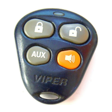
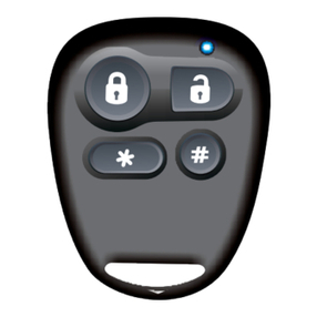
The standard key fob has three buttons; Lock, Unlock and Silent.
TTooAArrmmtthheessyysstteemm..
Press the Lock button of the fob. The alarm will beep twice and
flash the indicators twice. The system LED will start to flash after 5
seconds and the unit will monitor hot-wire, accessory switch,
movement and nudge. (The system will not arm if the ignition is
switched on).
TTooDDiissaarrmmtthheessyysstteemm..
Press the Unlock button. The system will give one short beep and
flash the indicators once.
NNOOTTEEIf the system gives one long beep this means the alarm has
been sounding. Enter diagnostics mode to find the reason why.
Convenience (Ferry) Mode
In Convenience mode the movement/nudge sensor will cease to function.
With the alarm active, press the Silent button. You will get one long tone and
one flash of the indicators.
If the LED flashes once/per second the movement sensing is active
If the LED flashes once every two seconds, the movement sensing is disabled.
You can ‘toggle’ between Convenience Mode enabled and disabled by simply
pressing the silent button.
Diagnostics Mode
It is possible to determine the trigger source that caused the alarm to sound.
Only the last reason is recorded.
Diagnostic mode can be accessed two ways;
a. When the alarm is sounding the LED will flash a number of times, pause,
then flash the same number again. This will go 30 seconds until the
system stops sounding.
b. Alternatively, disarm the alarm and then press the silent button. The LED
will flash a number of times and the system will beep the same number of
times. Every time you press the silent button the system will flash/beep in
accordance with the following table.
NNuummbbeerrooff
FFllaasshheess//BBeeeeppssTTrriiggggeerrRReeaassoonn
1No Triggers in last armed period
2
Power was interrupted (The SCOOTER does not have
an internal battery but if the power is disconnected
when the unit is armed, and then re-connected it will
give a reaction.)
3Ignition turned on or hot-wired
4Movement
5Accessory switch was operated

New Key Fob/Lost Key Fobs
5
IIffyyoouuccaannddiissaarrmmtthheessyysstteemm--iiee;;yyoouuhhaavveeaa
wwoorrkkiinnggffoobbaannddnneeeeddttooaaddddaannootthheerr;;
1. Switch ignition off
2. Disarm the system from the fob
3. NOTE Sections 4 and 5 must be completed
within 10 seconds
4. Switch the ignition on-off 5 times in quick
succession, leaving the ignition ON at the 5th
action
5. Change the state of the accessory switch
circuit - WHITE wire (ie; connect to ground if
not connected and vice versa) The unit will
beep once and enter learn mode
6. Press and hold the Lock button until the unit
beeps then release it
7. The unit will beep twice
8. Press and hold the Lock button again and the
unit will beep three times.
IIfftthheessyysstteemmiissddiiss--aarrmmeeddbbuuttyyoouuddoonn’’tthhaavveeaa
wwoorrkkiinnggffoobb((yyoouuhhaavveelloossttaallllwwoorrkkiinnggffoobbss));;
1. Switch off the scooter ignition
2. Remove alarm fuse
3. Leave for 5 minutes
4. Reconnect alarm fuse (and within 10 seconds
perform sections 5 & 6)
5. Switch the ignition on-off 5 times in quick
succession, leaving the ignition ON at the 5th
action
6. Change the state of the accessory switch
circuit - WHITE wire (ie; connect to ground if
not connected and vice versa) The unit will
beep once and enter learn mode
7. Press and hold the Lock button until the unit beeps
then release it
8. The unit will beep twice
9. Press and hold the Lock button again and the
unit will beep three times
IIfftthheessyysstteemmiissaarrmmeeddaannddyyoouuddoonn’’tthhaavveeaa
wwoorrkkiinnggffoobb((yyoouuhhaavveelloossttaallllwwoorrkkiinnggffoobbss));;
1. Ensure the scooter ignition is switched off.
2. Remove the alarm fuse
3. Leave for 5 minutes
4. Replace the alarm fuse - the alarm will sound
for 30 seconds (unless the system has sounded
10 times for power loss in which case there will
not be an audible reaction but wait 30 seconds)
Ensure the ignition is OFF during this time and
ensure the alarm is not triggered by accessory
switch or movement
5. Trigger the alarm by turning ON the ignition.
When the alarm sounds turn the ignition OFF.
When the siren stops after 30 seconds (ie;
during the quiet time) you have 10 seconds to
perform steps 6 & 7
6. Switch the ignition on and off 5 times, leaving
the ignition ON at the fifth action
7. Change the state of the accessory switch
circuit - WHITE wire (ie; connect to ground if
not connected and vice versa) The unit will
beep once and enter learn mode
8. Press and hold the Lock button until the unit beeps
then release it
9. The unit will beep twice
10. Press and hold the Lock button again and the
unit will beep three times.
NEW/REPLACEMENT/UPGRADED KEY FOBS CAN BE ORDERED
DIRECT FROM ACUMEN
www.acumen-electronics.co.uk

6
Troubleshooting
11..TThheeaallaarrmmwwiillllnnoottrreeaaccttttootthheeffoobb
a. Check the fob batteries (type CR2016).
b. Place the fob as near as possible to the alarm
system main unit. If it will now disarm there
are probably spurious radio signals in the
vicinity. Move the scooter to another area.
c. Check the system fuse. If the alarm has no
power it cannot power the radio receiver.
Switch on the scooter ignition - if it disarms
now the alarm’s power supply is at fault (fuse
or connections).
22..FFaallsseeaallaarrmmss..
RReemmeemmbbeerr!!TThheeaallaarrmmmmaayytthhiinnkkiittiissbbeeiinnggssttoolleenn,,
wwhhiicchhiissddiiffffeerreennttttooiittbbeeiinnggffaauullttyy!!
a. Enter Diagnostic mode and find out why the
alarm is/was reacting.
b. Take appropriate action - such as:
i. Enter Convenience Mode if it’s a windy
day (see page 4).
ii. Check earth/power connections if you
repeatedly get a ‘power interrupted’
signal.
33..TThheeaallaarrmmffuusseekkeeeeppssffaaiilliinngg..
The system cannot ‘blow’ the fuse. It is what the
alarm switches that blows the fuse - usually the
indicators. Make sure there are no shorts in the
indicator system and if a new fit, make sure the
alarm PINK wire(s) is/are not connected to the
negative side of one, or both of the m/c indicators.
Spares and Accessories
Acumen can supply a range of spares &
accessories to enhance the features of the
SCOOTER system:
1. Spare and replacement remote fobs and
batteries.
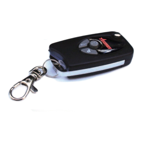
2. The key fob can be up-graded to the same flip-
fob as used on the Acumen ‘Thatcham’
specification CAT1 and CAT21 systems. The Flip-
fob uses Microchip KeeLoq®code-hopping
technology which prevents scanning and
recording of transmitter codes. When ordering,
specify Acumen part number 51020 and your
make, model and year of scooter.
NNOOTTEEThe Acumen SCOOTER cannot ‘know’ both
types of fob at the same time. If it ‘knows’ the
standard fob, it cannot ‘know’ a flip fob at the same
time. It can ‘know’ 2 x standard fobs at the same
time, or 2 x flip fobs at the same time, but not 1 of
each.
3. Different coloured System LED’s to match your
scooter (Green, Red, White, Blue, Yellow)
4. Acumax 900 Intelligent ‘float’ battery charger
5. Extra, external sirens. (If your SCOOTER
system is ‘buried’ in the scooter, the audible
warning may not be as loud as you would like.
This extra siren will allow you to position it
where the sound can get out.)
TThheeSSCCOOOOTTEERRccaannbbeeffuurrtthheerruuppggrraaddeedd;;
Upon request, Acumen will supply you, free of
charge, with a protecting ‘clamshell’ to prevent easy
disconnecting of the alarm system. The clamshell
will prevent easy unplugging of the 6-way
connector.
Please request Acumen part number C-07-0003
TThheeSSCCOOOOTTEERRaallssoohhaasstthheeaabbiilliittyyttoobbeeccoonnnneecctteedd
ttootthheeffoolllloowwiinnggooppttiioonnaallccoommppoonneennttss;;
1. Starter immobilisation kit
(Acumen part number 10113)
2. Acumen AlarmMate pager
(Acumen part number 10114)
GGeenneerraallSSeeccuurriittyyPPrreeccaauuttiioonnss..
While the Acumen SCOOTER provides state of the
art electronic security and protection, it will not, by
itself, ensure your scooter will not be stolen. We
recommend you undertake basic security
precautions such as;
Parking in a locked garage if possible,
Parking in well lit areas if a garage is not
applicable,
Using a bike cover where appropriate,
Using a chain or shackle and ground anchor.
WWaarrrraannttyytteerrmmssaannddCCoonnddiittiioonnss
Full details are given in the Terms and Conditions
document.
www.acumen-electronics.co.uk

Wiring Diagram
This manual suits for next models
1
Table of contents
Other Acumen Car Alarm manuals
