Acute DS-1000 User manual

Acute
─
1
─
Table of Contents
Safety Information
Safety Information.......................................................................................................... 2
Chapter 1: Introduction
What is the DS-1000 series digital storage oscilloscope .......................................... 5
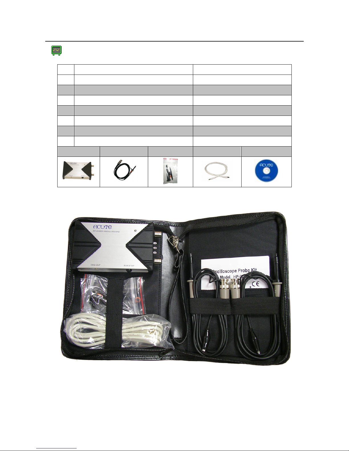
Packing list....................................................................................................................... 6
Specifications .................................................................................................................. 7
System Requirements .................................................................................................... 9
Chapter 2: Installation
Installation Procedures ..................................................................................................11
Quick Start: (Calibration)..............................................................................................15
Chapter 3: Operations
Screen................................................................................................................................17
Channel Switch Button..................................................................................................17
VOLTS/DIV Knob..........................................................................................................18
SEC/DIV Knob ................................................................................................................18
Main Function Button....................................................................................................19
Sub-Function Button......................................................................................................19
RUN/STOP Button .........................................................................................................19
Force Trigger....................................................................................................................19
AUTOSET ........................................................................................................................19
Set to 50% Button............................................................................................................20
Hard Copy Button...........................................................................................................20
Panel Switch Button.......................................................................................................21
Skin Panel ........................................................................................................................22
Threshold .........................................................................................................................22
Channel.............................................................................................................................22
Scroll Bar ..........................................................................................................................22
Panel Sizing Knob ..........................................................................................................22
Trigger...............................................................................................................................22
Chapter 4: Functionality
Trigger...............................................................................................................................24
Display..............................................................................................................................25
Cursor................................................................................................................................26
Measurement ...................................................................................................................27
Utility ................................................................................................................................27
Save/Recall.......................................................................................................................32
Acquire..............................................................................................................................33
Chapter 5: How to stack more than one DSO
How to stack more than one DSO ...............................................................................35
Chapter 6: Miscellaneous
Appendix..........................................................................................................................37

─
2
─
Safety Information
Please review the following safety information to avoid injury and to prevent damage
to the DS-1000 or any equipment connected to it.
Symbol definitions:
This symbol indicates that the manual should be referred to.
WARNING
WARNING denotes that, if not correctly performed or
adhered to, could result in injury or loss of life. Do not
proceed beyond a warning until the indicated conditions are
fully understood and met.
CAUTION
CAUTION denotes that, if not correctly performed or
adhered to, could result in damage to or destruction of the
DS-1000. Do not proceed beyond a caution sign until the
indicated conditions are fully understood and met.
NOTE
NOTE denotes to refer to the manual, which provides
operational information of which the user should be aware.
WARNING
Do not operate without cover(s) or panel(s).
Do not operate the DS-1000 with any cover(s) or panel(s) removed. This may
result in electric shock or fire hazard if any part(s) inside is touched.
Use USB2.0 power only
The DS-1000 is and should be powered by the PC’s USB2.0 port. Use only the DS-1000
USB cable within the DS-1000 soft case to connect to the PC’s USB2.0 port.
Do not operate in an explosive environment.
Do not operate in wet or damp conditions.
Safety Information

Acute
─
3
─
If there is smoke, abnormal smell or abnormal sound, unplug the USB cable from
the DS-1000 immediately.
Do not modify or operate the DS-1000 if there is any suspected damage; have it
inspected by qualified service personnel.
WARNING
Connect the Probe Properly
The probe ground lead is at ground potential. Do not connect the ground lead to
an elevated voltage. Connect the ground lead of the probe to earth ground only.
Do not connect or disconnect probes or test leads while they are probed to a
voltage source.
Use an attached USB cable
DC +5V is supplied by the USB port of the PC. Do not apply power from other
power source.
CAUTION
Observe ALL Terminal Ratings.
To avoid fire or shock hazard, observe all ratings and markings on the product.
Consult the product manual for further rating information before making
connections to the product.
Do not operate in the following environments
In direct sunlight.
In extremely hot and/or humidity areas.
With constant mechanical vibrations.
In areas with strong lines of magnetic forces or impulse voltage.
If not using the DS-1000 for an extended period, remove the USB cable from it.
Prohibited

─
4
─
Chapter 1
Introduction

Acute
─
5
─
What is the DS-1000 series digital storage oscilloscope?
The DS-1000 series is a PC-based, pocket-sized digital storage oscilloscope (DSO)
designed and manufactured by Acute Technology Inc. It has three models: DS-1002,
DS-1102, and DS-1202 with the same functionality as its stand-alone peers. Detailed
specifications are listed on the next page.
Easy to carry: It is very portable; notebook co-operability makes mobility easy.
Easy to use: Leverage the storage capacity and power of applications within a
PC/Notebook.

─
6
─
Packing list
Item DS-1000
1. Pocket-DSO mainframe 1
2. 250MHz probes (1x/10x) 2*
3. Probe accessory pack 2
4. USB A-B cable 1
5. Installation CD 1
6. Quick Manual 1
7. DSO soft case 1
1. 2. 3. 4. 5.
*
DS-1002 provides 2 100MHz probes (1x/10x).
Introduction

Acute
─
7
─
Specifications
DS-1000 Specifications
Acquisition
Mode Real-time sampling, Equivalent sampling, Roll mode, Average, Envelope
Input
Input Coupling AC, DC, GND
Input Impedance 1MΩ±1% // 21pF±5%
Max. Input Voltage 42Vpk (DC + AC peak)
Vertical
Channel 2 (DS-1202 allows stacking of up to max. 6 channels.)
Vertical Resolution 9 bits /channel @ 5mV/DIV- 10V/DIV (8 bits @ 2mV/DIV)
Sensitivity 2mV/DIV to 10V/DIV (as 2-5-10 step)
DS-1102, DS-1202
:
DC to 200MHz
Bandwidth DS-1002:
DC to 100MHz
Bandwidth Limitation Approx. 20MHz
Range 8 divisions
Offset Level ±4 divisions
Offset Increments 0.1 division
DC accuracy ±3%
Time Base
DS-1102, 1202
:
Real-time sampling: 200MS/s @ 1Ch, 100MS/s @2Ch(Single Shot)
Equivalent sampling: 5GS/s (Repetitive)
Sampling Rate DS-1002: Real-time sampling: 100MS/s @ 1Ch, 50MS/s @2Ch(Single Shot)
Equivalent sampling: 2.5GS/s (Repetitive)
Time Base Range 2ns/DIV to 10s/DIV (as 2- 5-10 step)
Accuracy 100ppm
Range 10 Divisions
Delay Trigger 320 Divisions (DS-1002, 1102), 2,560 Divisions (DS-1202)
Time Resolution 200ps
DS-1002, 1102:
2k points/channel to 64k points/channel
DS-1202: 2k points/channel to 512k points/channel
Record Length
Roll Mode: 32k points/channel (Log Length = Hard Disk limitation)
Trigger
Type Rising, Falling, Delay-Trigger, TV-Trigger (DS-1002 no TV trigger)
Mode Auto, Normal and Single (with RUN/STOP hardware button on the DSO device)
Source CH1, CH2, Ext-Trig
Coupling DC, HF rejection
Sensitivity 5mV/DIV~10V/DIV=1div, 2mV/DIV=1.5div
Trigger Level ±4 divisions
Trigger Increments 0.1 division
Measurement and Processing
Special function Auto set, Monitor from Internet (TCP/IP)

─
8
─
Measurement
Vpp, Vmax, Vmin, Vamp, Vtop, Vbase, Vupper, Vmiddle, Vlower, Vmean, Vrms, Positive
overshoot, Negative overshoot, Period, Frequency, Pulse width
Cursor Time difference, Voltage difference
Math Add, Sub, Multiplication, Division
FFT Rectangular (Vertical scale: dbV RMS, Linear RMS)
Export Data WORD, EXCEL, CSV, TEXT, HTML, Clipboard, Hardcopy, Preview
Trigger Input/Output
EXT-TRIG Input Limitation TTL Level
EXT-TRIG Acknowledge Level
1.6V to 5V, rising/falling edge
EXT-TRIG Acknowledge Freq. “>10ns” and “>0.1 TIME/DIV”
TRIG-OUT 3.3v rising edge, 20ns delay after trigger occurs (only for DS-1202 stack function)
Calibration Output
Level Approx. 3.3V
Frequency 1kHz ±0.5%
Environment
Operation 0℃to +50℃
Storage -10℃to +60℃
Physical
Interface USB2.0 (USB1.1 compatible)
Power USB bus power
Dimension (device only) 135x80x26mm
Weight (device only) 230 g
Accessories
DS-1102, 1202:
250MHz probe (1x/10x) x2
Probes DS-1002: 100MHz probe (1x/10x) x2
Others Installation CD, USB2.0 cable, User manual, Soft case.
DS-1202 Spec. Limitations in Stack Mode
Acquisition
Mode Real-time sampling, Average, Envelope
Equivalent sampling and Roll mode only available in the Master-DSO
Time Base
Sampling Rate Real-time sampling: 200MS/s @ 1Ch/DSO, 100MS/s @ 2Ch/DSO
Equivalent sampling: 5GS/s only for the Master-DSO
Time Base Range 2ns/DIV to 100ms/DIV (as 2-5-10 step) for the Master and the Slave DSOs
200ms/DIV to 10s/DIV (Roll mode) only for the Master-DSO
Trigger
Source CH1, CH2, Ext-trig in the Master-DSO (N/A for the Slave-DSO)
Jitter +/- 200ps in the Master-DSO; +/- 10ns in the Slave-DSO
Introduction

Acute
─
9
─
System Requirements
♦
Pentium 1.2GHz (or higher compatibles), Pentium 2.0GHz CPU (or higher)
recommended.
♦
PC memory 64M bytes of RAM minimum.
♦
At least 32M bytes of available hard disk space.
♦
CD-ROM drive (for installation).
♦
Display specification, 640x480 VGA (or higher), 800x600 or 1024x768
recommended.
♦
101 keyboard, Windows keyboard recommended.
♦
2 or 3 buttons mouse.
♦
USB port (USB2.0 preferred, USB1.1 acceptable)
♦
Printer (optional).
♦
Microsoft Windows 98se/ME/NT/2000/XP OS.

─
10
─
Chapter 2
Installation

Acute
─
11
─
Installation Procedures
Device Driver Installation for Windows98se
1. Insert installation CD, if you see a hardware wizard, please cancel it. Then
connect the USB cable to the DS-1000 and the PC or notebook computer.
2. Windows will find a USB device automatically and enter the hardware wizard
(Figure 1).
Figure 1 Figure 2
3. Choose “Search for the best driver for your device. (Recommended)” to find
the proper driver automatically (Figure 2).
4. Choose “CD-ROM Drive”, and click “Next” (Figure 3).
Figure 3 Figure 4
5. A proper driver will be found, click “Next” (Figure 4).
6. If your PC doesn’t have an “usbscan” driver, the wizard will need a Window
OS CD-ROM to install it.
7. Click “Finish” (Figure 5) once Windows has installed the DSO driver.
Figure 5 Figure 6

─
12
─
8. You may see “Acute USB 2.0 Interface” in Device Manager (Figure 6). It
means that the DS-1000 USB interface is installed. If an exclamation or question
mark appears on the ““Acute USB 2.0 Interface”, that indicates the device is in a
problem state. Please visit the FAQ page of our web site at http://www.acute.com.tw
Device Driver Installation for Windows 2000
1. Insert installation CD, if you see a hardware wizard, please cancel it. Then
connect the USB cable to the DS-1000 and the PC or notebook computer.
2. Windows will find a USB device automatically and enter the hardware wizard.
(Figure 1)
Figure 1 Figure 2
3. Choose “Search for a suitable driver for my device (Recommended)” to find
the proper driver automatically (Figure 2).
4. Choose “CD-ROM Drive”, and click “Next” (Figure 3).
Figure 3 Figure 4
5. A proper driver will be found, click “Next” (Figure 4).
6. Click “Finish” (Figure 5) once Windows has installed the DSO driver.
7.
You may see the “Acute USB 2.0 Interface” in Device Manager (Figure 6). It
means that the DS-1000 USB interface is installed. If an exclamation or question
mark appears on the “Acute USB 2.0 Interface”, that indicates the device is in a
In
stallation

Acute
─
13
─
problem state. Please visit the FAQ page of our web site at http://www.acute.com.tw
Figure 5 Figure 6
Device Driver Installation for Windows XP
1. Insert installation CD, if you see a hardware wizard, please cancel it. Then
connect the USB cable to the DS-1000 and the PC or notebook computer.
2. Windows will find a USB device automatically and enter the hardware wizard
(Figure 1). Choose “yes. This time only”.
Figure 1 Figure 2
3. Choose “Install the software automatically (Recommended)” to find the proper
driver automatically (Figure 2). Click “Next”.
4. Windows will search for a proper driver for the DS-1000 (Figure 3); this could
take a while.
Figure 3 Figure 4
5. Click “Finish” (Figure 5) once Windows has installed the DSO driver.

─
14
─
6.
You may see the “Acute USB 2.0 Interface” in Device
Manager (Figure 6). It means that the DS-1000 USB
interface is installed. If an exclamation or question mark
appears on the “Acute USB 2.0 Interface”, that indicates the
device is in a problem state. Please visit the FAQ page of our
web site at http://www.acute.com.tw or email us at
Application Installation
1. When you want to install the latest version of the DS-1000 Application (AP)
software, please REMOVE the current DS-1000 AP in your PC. This will
NOT change any existing project file(s) or environment parameter(s).
2. Insert the installation CD into the CD-ROM drive.
3. Double click the CD-ROM drive icon to enter the auto-installation procedure.
If there is no response, run setup.exe from the CD-ROM root directory. The CD
has other application software for other Acute products, such as logic analyzer
and programmable data generator. The software, if installed, will enter DEMO
mode since no such hardware exists.
4. Change the default folder if you want to use another directory.
5. Start the DSO software installation.
6. Once the installation is completed, you may find the DSO icon either on the
Desktop or in the Programs group. You may double click either icon to start
the DSO AP.
7. If you enter “DEMO Mode” when you launch the DS-1000 AP, this means that
some problem has occurred. Please contact your dealer or email us at
In
stallation

Acute
─
15
─
Quick Start: (Calibration)
1. Connect the two probes to the DS-1000’s Channel 1 and Channel 2 BNC connectors.
2. Switch the Probe to “x10”.
3. Connect the two probe ground leads to the DS-1000’s ground terminal.
4. Connect the two probe tips to the DS-1000’s “Probe Comp. (3.3V)” terminal.
5. Launch the DSO AP from Windows Desktop.
6. Push the “Auto Set” button.
7. If you see the waveforms shown below:
Adjust the trimmer located in the probe’s BNC plug to obtain a flat-top square
waveform as shown below.
8. Switch the Probe to the “REF” position.
9. Push the “Utility” button.
10. Push “Calibration” Function Button.
11. During calibration, the DSO AP will ask you to switch the Probe to”x10”.
12. Once calibration has finished, you can change the time base or vertical division to
check the result of the calibration.

─
16
─
Chapter 3
Operations

Acute
─
17
─
Screen
Channel Switch Button
There are 6 channels, CH1, CH2…, CH6 on the upper right corner of the
panel as shown above. When you are operating one DSO-1000, only CH1
and CH2 are available and the rest of the channel buttons, with gray font,
are not available like CH3 - CH6 as shown on the left. (CH3, CH4)/(CH3,
CH4, CH5, CH6) are available if two/three of the DSO-1000 units are
stacked. CH1, with gray button and black font, as shown on the left, is
available but not activated. If you click on the CH2 button, its functions
will be activated and its color turns to blue as shown on the left. Each
activated channel button has its own color, which is identical to that of the
waveform of the channel.
CH2 Waveform
Function Information
Sub
-
Function Button
Scroll Bar
C
hannel Select
.
Waveform
Vert. Adj.
Waveform Horz. Adj.
Panel
Sizing
Main
F
unction Button
Panel Switch Button
Shortcut
Button
CH1 Waveform

─
18
─
VOLTS/DIV Knob
The VOLTS/DIV knob is used to change the vertical voltage scale. On the screen’s
lower-left corner, a voltage scale (for each division is) displayed. There are 8
vertical divisions on the screen. For example, if the corner displays “CH1 2.00V”,
this means that the voltage scale is 2 Volts for each vertical division and the voltage
distance from top to bottom of all 8 divisions on the screen is 16 Volts. There are
two small buttons near the VOLTS/DIV knob; one is “-“(zoom out), the other is “+”
(zoom in). You can click your mouse’s left button (or “-“) or the right button (or
“+”) on the VOLTS/DIV knob to increase or decrease the voltage scale. Also, the
mouse wheel (if so equipped) can be used to adjust the voltage scale even faster.
SEC/DIV Knob
The SEC/DIV knob is used to change the time scale. On the upper center of the
screen, a time scale is displayed. This represents each horizontal time division, set
to 50us in the example above. You can move the mouse to the SEC/DIV knob and
then click the left or right button of the mouse to increase or decrease the time scale.
If your mouse has a wheel, you can use the wheel to quickly adjust the time scale.
There are two small buttons near the SEC/DIV knob. One is “–”, the other is “+”.
These two small buttons are used for adjusting the time scale if the mouse has only
one button.
On the screen’s upper-center edge, a time scale for each division is displayed.
There are 10 divisions on the screen. For example, if the time scale displays “M 50µs”,
this means that the time scale is 50 µs for each horizontal division. There are two
small buttons near the SEC/DIV knob; one is “-“(zoom out), the other is “+” (zoom
in). You can click your mouse’s left button (or “-“) or the right button (or “+”) on
the SEC/DIV knob to increase or decrease the time scale. Also, the mouse wheel (if
so equipped) can be used to adjust the time scale even faster.
Operations

Acute
─
19
─
Main Function Button
There are seven main function buttons: Trigger, Display, Cursor, Measure, Utility,
Save/Recall, and Acquire under the Full mode screen. When you disconnect the
DS-1000 from your PC and launch the DSO AP, the program automatically changes
to Demo mode and the Acquire button becomes the Demo button. If you still want
to use the Acquire function under Demo mode, please switch the DSO AP to Skin
mode, then you can find the Acquire function under the pull-down function menu
on upper right corner.
Sub-Function Button
There are ten sub-function buttons, which work in conjunction with the seven main
function buttons. However, not all sub functions are available in each main
function. You may trigger each sub function by clicking the left or right button of
the mouse. For example, [if you] click the right button of the mouse under the sub
function for probe type, the sub function will be activated in this order: “x1”, “x10”,
“x100”. Clicking the right button under the same sub function activates the sub
function in the opposite order: “x100”, “x10” or “x1”.
RUN/STOP Button
The Run/Stop button runs or stops the signal acquisition process. The DS-1000
also has a hot key RUN/STOP button, which performs the same function. This
button is on the side of the DS-1000 units.
FORCE TRIGGER Button
When the TRIGGER is set to Normal or Single Shot mode and the unit is not
triggered, the “FORCE TRIGGER” button is used to force the DS-1000 to trigger.
AUTOSET Button
DS-1000 will automatically adjust its Voltage, Time, and Trigger parameters for the

─
20
─
signals under test to display their waveforms. However, it could take some time
for the DS-1000 to do so due to the many possible combinations of DS-1000
parameters and signal characteristics. So, the “AUTOSET” button is used to adjust
Voltage, Time, and Trigger parameters of the DS-1000 for tested signals and display
the signals’ waveform more quickly than may be achieved manually. The
“AUTOSET” button, when pushed, will find the parameters of the signal applied to
the active channel. For example, if the “Channel Switch” button is set to CH1, then
the Voltage, Time, and Trigger parameters of the CH1 signal(s) will be the
benchmark parameters used for the “AUTOSET” function.
Set to 50% Button
Pushing the “Set to 50%” button will cause the DS-1000 to fine tune the trigger level
to the mean voltage of the trigger signal.
Hard Copy Button
The “Hard Copy” button can be used to print (hard copy) the waveform on the
screen to the default printer. Also, you may generate output with different
parameters in “Preview” under the ”Export” sub-function of the Utility main
function.
Operations
Table of contents
Popular Network Storage Server manuals by other brands

Western Digital
Western Digital WDH1NC10000N - My Book World Edition NAS... user manual

Dell
Dell PowerVault NX3600 release note

Acer
Acer Aspire easyStore H340 Manuel d'utilisation

Cisco
Cisco UCS S3260 Service note

Dell
Dell PowerEdge R410 Technical guide

Synology
Synology DiskStation DS1817+ Hardware installation guide

NETGEAR
NETGEAR RNDP600E - ReadyNAS Pro Pioneer Edition NAS... installation guide

Plextor
Plextor StorX Quick setup guide

EMC
EMC CLARiiON CX4-960 Setup guide

Seagate
Seagate 8-BAY RACKMOUNT NAS quick start guide

QUANTA
QUANTA STRATOS S210 Series S210-X22RQ Technical guide

American Megatrends
American Megatrends StorTrends 3200 Setup guide