Acute TravelScope Series User manual

Acute Technology Inc.
Copyright 2018
TravelScope DSO Manual
Publish:2018/08

i
Acute Technology Inc.
Copyright 2018
T
Ta
ab
bl
le
e
o
of
f
C
Co
on
nt
te
en
nt
ts
s
S
Sa
af
fe
et
ty
y
I
In
nf
fo
or
rm
ma
at
ti
io
on
n
-
--
--
--
--
--
--
--
--
--
--
--
--
--
--
--
--
--
--
--
--
--
--
--
--
--
--
--
--
--
--
--
--
--
--
--
--
--
--
--
--
--
--
--
--
--
--
--
--
--
--
--
--
--
--
--
--
--
--
--
--
--
--
--
--
--
--
--
--
--
-
1
1
C
Ch
ha
ap
pt
te
er
r
1
1
I
In
ns
st
ta
al
ll
la
at
ti
io
on
n
-
--
--
--
--
--
--
--
--
--
--
--
--
--
--
--
--
--
--
--
--
--
--
--
--
--
--
--
--
--
--
--
--
--
--
--
--
--
--
--
--
--
--
--
--
--
--
--
--
--
--
--
--
--
--
--
--
--
--
--
--
--
--
--
-
3
3
Installation Procedures ----------------------------------------------------------------------------------- 4
Probe calibration------------------------------------------------------------------------------------------- 9
DS-1000 series Calibration----------------------------------------------------------------------------- 11
C
Ch
ha
ap
pt
te
er
r
2
2
O
Op
pe
er
ra
at
ti
io
on
ns
s
-
--
--
--
--
--
--
--
--
--
--
--
--
--
--
--
--
--
--
--
--
--
--
--
--
--
--
--
--
--
--
--
--
--
--
--
--
--
--
--
--
--
--
--
--
--
--
--
--
--
--
--
--
--
--
--
--
--
--
--
--
--
--
-
1
12
2
Window----------------------------------------------------------------------------------------------------- 13
Operation--------------------------------------------------------------------------------------------------- 14
Channel Switch Button ----------------------------------------------------------------------------------------------14
VOLTS/DIV Knob ---------------------------------------------------------------------------------------------------14
TIME/DIV Knob------------------------------------------------------------------------------------------------------14
Threshold --------------------------------------------------------------------------------------------------------------15
Channel-----------------------------------------------------------------------------------------------------------------15
Trigger Position-------------------------------------------------------------------------------------------------------15
Scroll Bar --------------------------------------------------------------------------------------------------------------16
Panel Sizing Knob----------------------------------------------------------------------------------------------------16
Zoom(TravelScope only)--------------------------------------------------------------------------------------------16
Waveform operation--------------------------------------------------------------------------------------------------17
C
Ch
ha
ap
pt
te
er
r
3
3
M
Ma
ai
in
n
F
Fu
un
nc
ct
ti
io
on
n
B
Bu
ut
tt
to
on
n
-
--
--
--
--
--
--
--
--
--
--
--
--
--
--
--
--
--
--
--
--
--
--
--
--
--
--
--
--
--
--
--
--
--
--
--
--
--
--
--
--
--
--
--
--
--
--
--
-
1
18
8
Run/Stop ---------------------------------------------------------------------------------------------------------------18
FORCE TRIGGER---------------------------------------------------------------------------------------------------18
SET LEVEL TO 50%------------------------------------------------------------------------------------------------18
HARDCOPY----------------------------------------------------------------------------------------------------------18
TRIGGER--------------------------------------------------------------------------------------------------------------19

ii
Acute Technology Inc.
Copyright 2018
DISPLAY --------------------------------------------------------------------------------------------------------------30
CURSOR---------------------------------------------------------------------------------------------------------------38
MEASURE ------------------------------------------------------------------------------------------------------------39
UTILITY---------------------------------------------------------------------------------------------------------------41
SAVE/RECALL ------------------------------------------------------------------------------------------------------47
ACQUIRE -------------------------------------------------------------------------------------------------------------49
AUTOSET-------------------------------------------------------------------------------------------------------------52
C
Ch
ha
ap
pt
te
er
r
4
4
H
Ho
ow
w
t
to
o
s
st
ta
ac
ck
k
m
mu
ul
lt
ti
ip
pl
le
e
D
DS
SO
Os
s
-
--
--
--
--
--
--
--
--
--
--
--
--
--
--
--
--
--
--
--
--
--
--
--
--
--
--
--
--
--
--
--
--
--
--
--
--
--
--
--
--
-
5
53
3
How to stack multiple DSOs--------------------------------------------------------------------------- 54
APPENDIX------------------------------------------------------------------------------------------------ 57
Probe Specification---------------------------------------------------------------------------------------------------57

1
Acute Technology Inc.
Copyright 2014
Safety Information
Please review the following safety information to avoid injury and prevent damage to the
DSO or any products connected to it.
Symbol definitions:
This symbol indicates that the manual should be referred to.
WARNING
“WARNING” denotes that, if not correctly performed or adhered to,
could result in injury or loss of life. Do not proceed beyond a warning
until the indicated conditions are fully understood and met.
CAUTION
“CAUTION” denotes that, if not correctly performed or adhered to,
could result in damage to or destruction of DSO. Do not proceed
beyond a caution sign until the indicated conditions are fully
understood and met.
NOTE
“NOTE” denotes that refer to the manual, which provides operational
information of which the user should be aware.
WARNING
Do not operate without cover(s).
Do not operate the DSO with any cover(s) removed. This may result in electric shock or
fire hazard if any part(s) inside is touched.
Use USB2.0 power only
The DSO should be powered by the PC’s USB2.0 port. Use only the DSO USB cable to
connect to the PC’s USB2.0 port.
Do not operate in wet or damp conditions.
Do not modify or operate the DSO if there was any suspected damage, have it
2
Acute Technology Inc.
Copyright 2014
inspected by qualified service personnel.
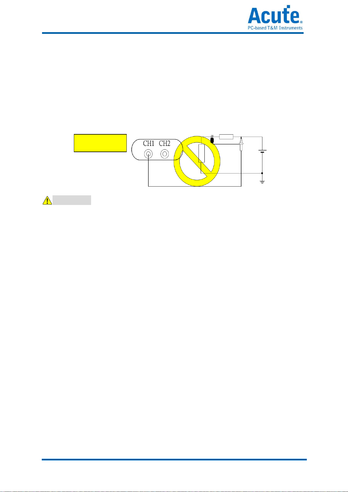
Connect the Probe Properly
Connect the ground lead of the probe to earth ground only. Do not connect the ground
lead to an elevated voltage.
Do not connect or disconnect probes or test leads while they are probed to a voltage
source.
CAUTION
ObserveALLTerminal Ratings.
To avoid fire or shock hazard, observe all ratings and markings on the product. Consult
the product manual for further ratings information before making connections to the
product.
Do not operate in the following installation location
In direct sunlight.
In extremely hot and/or humidity areas.
With always mechanical vibrations.
Around areas with strong lines of magnetic forces or impulse voltage.
Remove the USB cable from the DSO if it is not being used.
The temperature of the DSO increases after being used for a while.
Use original USB cable.

3
Acute Technology Inc.
Copyright 2014
C
Ch
ha
ap
pt
te
er
r
1
1
Installation

4
Acute Technology Inc.
Copyright 2014
Installation Procedures
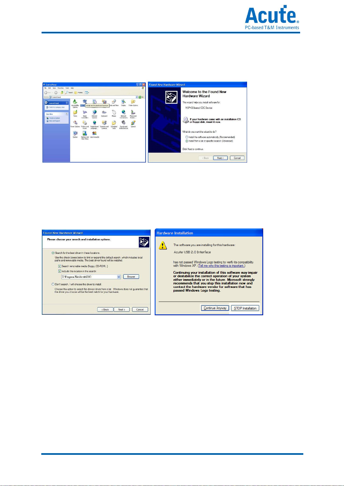
Driver Installation for Windows XP
Insert the installation CD and connect the DSO with your PC.
Enter the hardware wizard when the Windows OS find an USB device (Figure 1) and check
“yes. This time only”.
Figure 1 Figure 2
Choose “Install the software automatically” (Recommended) to find the proper driver
automatically (Figure 2). Click “Next”.
Click “Next” when a driver is found.
Figure 3 Figure 4
You will see the “Acute USB 2.0 Interface” in the Device Manager (Figure 6). Please check
installation problem.

5
Acute Technology Inc.
Copyright 2014
Figure 5 Figure 6
6
Acute Technology Inc.
Copyright 2014
Install the driver manually
Insert the installation CD and connect the DSO with your PC. Choose “Add Device” in the
Control panel (Figure 1).
Figure 1 Figure 2
Choose “Install from a list or specific location (Advanced)” (Figure 2) and click “Next”.
Choose “Search for the best driver in these locations”(Figure 3); select the DSO directory
and click “Next”.
Figure 3 Figure 4
Click “Continue Anyway” (Figure 4) to continue the installation procedure.
Click “Finish” (Figure 5) after the DSO driver is installed. You may see the “Acute USB 2.0
Interface” in Device Manager (Figure 6).


8
Acute Technology Inc.
Copyright 2014
Install the DSO software
Insert the installation CD into your PC.
Double click the auto-installation procedure. Run setup.exe at the CD-ROM root directory
if the auto-installation does not work. The DSO software will enter DEMO mode if the
DSO is not connected with the PC.
You will find the DSO software icon ( )after the installation.
If the DSO software enters “DEMO Mode” when the DSO is connected with your PC, please

9
Acute Technology Inc.
Copyright 2014
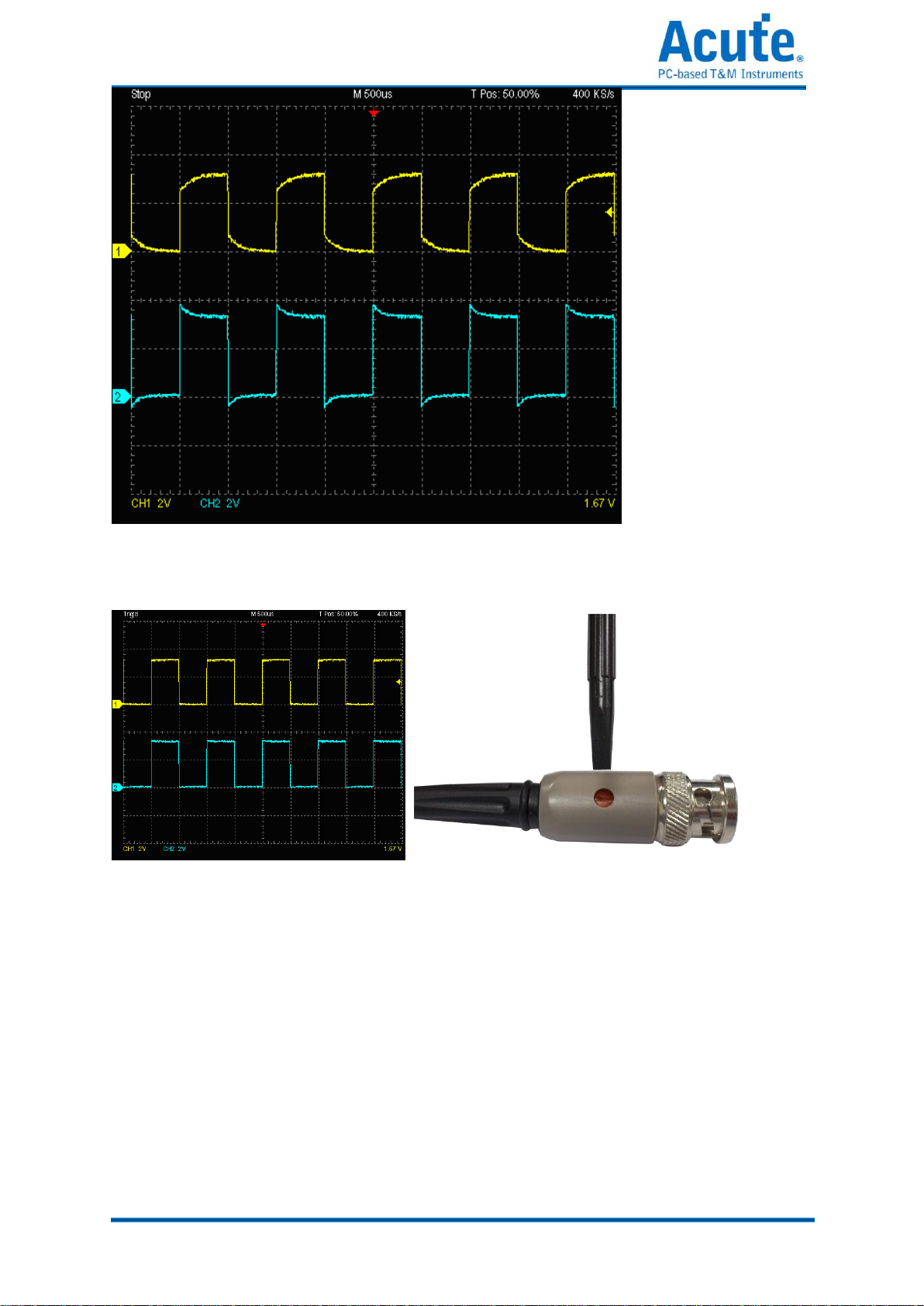
Probe calibration
Please calibrate the two probes at the first time use.
Connect the two probes with DSO’s 2 channels.
Switch the Probe to “x10”.
Connect two probe ground pins with the DSO’s ground terminator.
DS-1000: Connect two probes with the “Probe Comp. (3.3V)” pin.
TravelScope: Connect two probes with the “GEN 1” pin.
Run the DSO software.
Set the Volt/div = 2v and the Time/div = 500us.
If you see the waveforms below, please follow step (8).
10
Acute Technology Inc.
Copyright 2014
Adjust the trimmer near the probe’s BNC connector and modify the waveform to the
following shapes.

11
Acute Technology Inc.
Copyright 2014
DS-1000 series Calibration
Please calibrate the DS-1000 whenever the DSO connected with a different PC. Connect the
two probes with DSO’s 2 channels.
Switch the Probe to “x10”.
Connect two probes with the DSO’s ground terminator.
DS-1000: Connect two probes with the “Probe Comp. (3.3V)” pin.
Switch the Probe to “REF” position.
Push the “Utility” button.
Push “Calibration” of Function Button.
The calibration software will ask you to switch the Probe to”x10”.
You can change the time base or vertical division after the calibration to check the result.
You need to calibrate the DSO again each time you use a different PC because the calibration
information is stored in the PC.

12
Acute Technology Inc.
Copyright 2014
C
Ch
ha
ap
pt
te
er
r
2
2
Operations

13
Acute Technology Inc.
Copyright 2014
Window
You can use the mouse wheel to zoom in and zoom out the waveform on the screen and use
the left mouse button to drag and flicker the waveform. You can also use the mouse right
amount of measured specific area of the waveform.

14
Acute Technology Inc.
Copyright 2014
Operation
Channel Switch Button
There are 12 channel buttons (CH1, CH2…, CH12) on the upper right of the
DSO software window. When you use one DSO, only CH1 and CH2 are
available and the rest channel buttons will be disabled in gray color. CH1,
with gray button and black fonts, is available but not activated; CH2 is in
blue color when activated. Each activated channel button has its own color
which is identical to that of its waveform. Click the channel button will
turn on the display of the channel on the waveform window and right-click
to turn it off.
VOLTS/DIV Knob
The VOLTS/DIV knob is used to change the voltage scale. There are 8
vertical divisions for the voltage scale on the software window and the
voltage scale is shown on the window’s lower-left corner.. For example,
the window will display “CH1 2.00V”if the voltage scale is 2 Volts for each
vertical division and the total voltage of all 8 vertical divisions are 16 Volts. There are two
small buttons under the VOLTS/DIV knob, one is “-“(zoom out) and the other is “+” (zoom
in). The mouse wheel can be used to adjust the voltage scale faster.
TIME/DIV Knob
The TIME/DIV knob is used to change the time scale. There are 10 horizontal
time divisions on the waveform window. When the TIME/DIV shows “M
50us”, it means each horizontal division is 50us. There are two small buttons
under the TIME/DIV knob, one is “–” (zoom out) and the other is “+” (zoom in)

15
Acute Technology Inc.
Copyright 2014
to change the time scale, or use the mouse wheel to zoom in / zoom out. The waveform can
be drag and flicker by mouse left button.
The mouse wheel can be used to adjust the time scale faster.
Threshold
Threshold is an arrow sign on the right of the waveform window. You can move the arrow to
adjust the threshold value that is shown, on the lower right of the waveform window.
Channel
The channel numbers are shown on the left of the waveform window; you may move the
channel to adjust its threshold.
Trigger Position
The trigger is a red arrow sign on the top of the waveform window; you can drag the trigger
sign to adjust its time.

16
Acute Technology Inc.
Copyright 2014
Scroll Bar
The scroll bar is a light blue line under the waveform window. You can move the waveform
or the scroll bar to see the waveforms in different time or you can double click the scroll bar
to move the waveforms to the center (50%) of the time
Panel Sizing Knob
You can move the panel sizing knob on the lower right of the panel to adjust the size of the
panel.
Zoom(TravelScope only)
Press the button to on/off the zoom window; also use the hot key (z) to on/off it.
17
Acute Technology Inc.
Copyright 2014
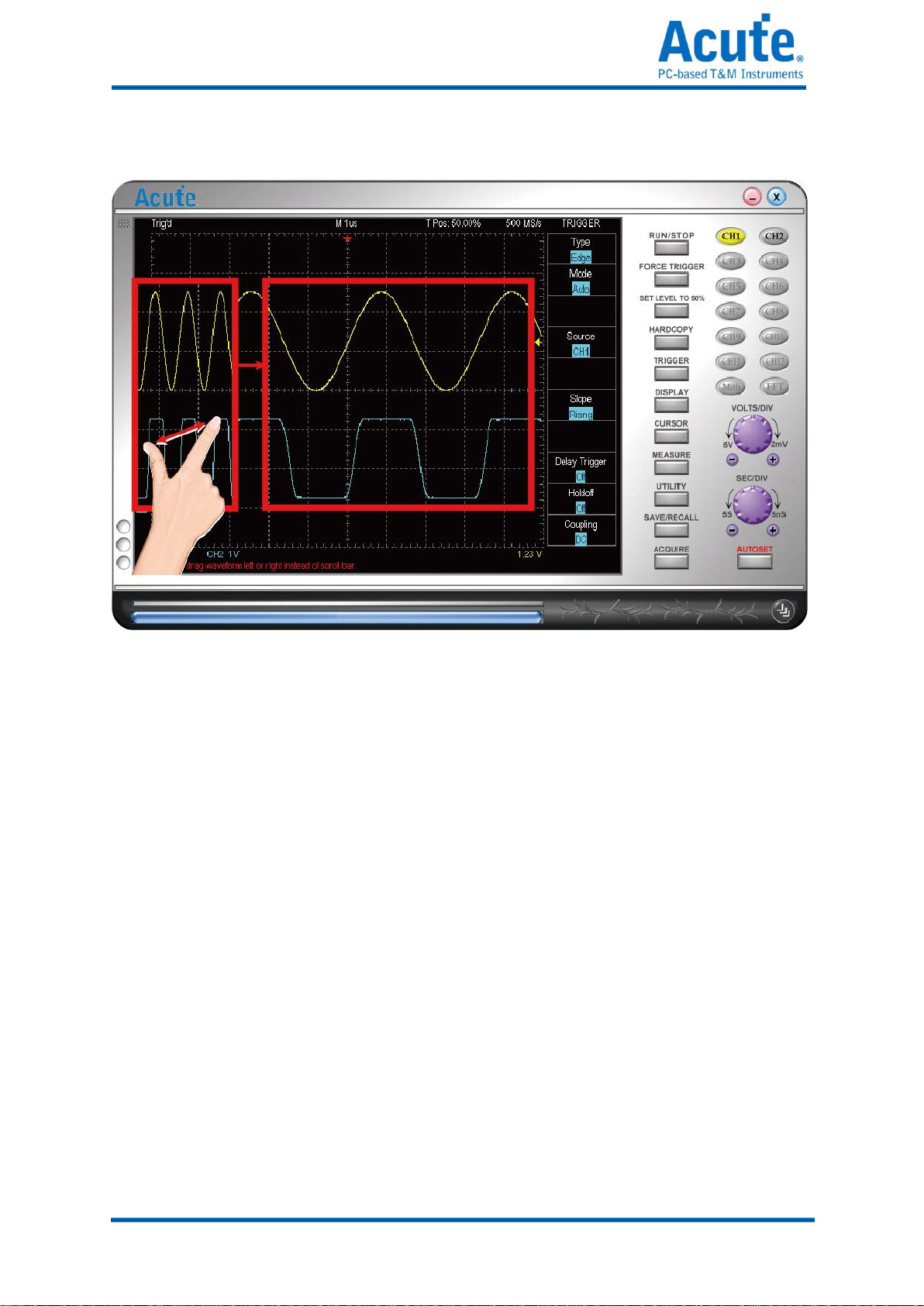
Waveform operation
Support multi touch.
Easy display of the waveform: You may drag the waveforms or roll the mouse wheel to
zoom in/out the waveforms.
Fast measurements: Right-click the selected waveform area for its measurements.
Fast voltage offset: Right-click the selected waveform area for its voltage offset
View In Secondary Display Window: Display the zoomed waveform of selected area in
secondary display window.
Other manuals for TravelScope Series
1
This manual suits for next models
5
Table of contents
Other Acute Test Equipment manuals


