Acute TravelScope Series User manual

i
Acute Technology Inc.
Copyright 2011
TravelScope series
Version: 1.2.1
Publish: 2012.7

ii
Acute Technology Inc.
Copyright 2011
T
Ta
ab
bl
le
e
o
of
f
c
co
on
nt
te
en
nt
ts
s
S
Sa
af
fe
et
ty
y
I
In
nf
fo
or
rm
ma
at
ti
io
on
n
-
--
--
--
--
--
--
--
--
--
--
--
--
--
--
--
--
--
--
--
--
--
--
--
--
--
--
--
--
--
--
--
--
--
--
--
--
--
--
--
--
--
--
--
--
--
--
--
--
--
--
--
--
--
--
--
--
--
--
--
--
--
--
--
--
--
--
--
--
--
-
1
1
C
Ch
ha
ap
pt
te
er
r
1
1
I
In
nt
tr
ro
od
du
uc
ct
ti
io
on
n
-
--
--
--
--
--
--
--
--
--
--
--
--
--
--
--
--
--
--
--
--
--
--
--
--
--
--
--
--
--
--
--
--
--
--
--
--
--
--
--
--
--
--
--
--
--
--
--
--
--
--
--
--
--
--
--
--
--
--
--
--
--
--
-
3
3
1.1 The Acute digital storage oscilloscope (DSO)--------------------------------------------------4
1.2 Specifications-------------------------------------------------------------------------------------------5
1.3 The DS-1000 packing list ------------------------------------------------------------------------- 12
1.4 The TravelScope packing list--------------------------------------------------------------------- 13
1.5 System Requirement-------------------------------------------------------------------------------- 14
C
Ch
ha
ap
pt
te
er
r
2
2
I
In
ns
st
ta
al
ll
la
at
ti
io
on
n
-
--
--
--
--
--
--
--
--
--
--
--
--
--
--
--
--
--
--
--
--
--
--
--
--
--
--
--
--
--
--
--
--
--
--
--
--
--
--
--
--
--
--
--
--
--
--
--
--
--
--
--
--
--
--
--
--
--
--
--
--
--
-
1
15
5
2.1 Installation Procedures----------------------------------------------------------------------------- 16
2.2 Probe calibration------------------------------------------------------------------------------------- 21
2.3 DS-1000 series Calibration------------------------------------------------------------------------ 23
C
Ch
ha
ap
pt
te
er
r
3
3
O
Op
pe
er
ra
at
ti
io
on
ns
s
-
--
--
--
--
--
--
--
--
--
--
--
--
--
--
--
--
--
--
--
--
--
--
--
--
--
--
--
--
--
--
--
--
--
--
--
--
--
--
--
--
--
--
--
--
--
--
--
--
--
--
--
--
--
--
--
--
--
--
--
--
--
--
-
2
24
4
3.1 Window------------------------------------------------------------------------------------------------ 25
3.2 Operation---------------------------------------------------------------------------------------------- 26
3.2.1 Channel Switch Button --------------------------------------------------------------------------------- 26
3.2.2 VOLTS/DIV Knob -------------------------------------------------------------------------------------- 26
3.2.3 TIME/DIV Knob ---------------------------------------------------------------------------------------- 26
3.2.4 Panel Switch Button ------------------------------------------------------------------------------------ 27
3.2.5 Skin Panel ------------------------------------------------------------------------------------------------ 28
3.2.6 Threshold------------------------------------------------------------------------------------------------- 29
3.2.7 Channel--------------------------------------------------------------------------------------------------- 29
3.2.8 Trigger Position------------------------------------------------------------------------------------------ 29
3.2.9 Scroll Bar------------------------------------------------------------------------------------------------- 30
3.2.10 Panel Sizing Knob--------------------------------------------------------------------------------------- 30

iii
Acute Technology Inc.
Copyright 2011
3.2.11 Main Function Button----------------------------------------------------------------------------------- 30
C
Ch
ha
ap
pt
te
er
r
4
4
H
Ho
ow
w
t
to
o
s
st
ta
ac
ck
k
D
DS
SO
Os
s
-
--
--
--
--
--
--
--
--
--
--
--
--
--
--
--
--
--
--
--
--
--
--
--
--
--
--
--
--
--
--
--
--
--
--
--
--
--
--
--
--
--
--
--
--
--
--
--
--
--
--
--
-
4
49
9
4.1 How to stack DSOs --------------------------------------------------------------------------------- 50
4.2 APPENDIX------------------------------------------------------------------------------------------- 51
4.2.1 Index ------------------------------------------------------------------------------------------------------ 51
4.2.2 Probe Specification-------------------------------------------------------------------------------------- 52

1
Acute Technology Inc.
Copyright 2012
Safety Information
Please review the following safety information to avoid injury and prevent damage to the
DS-1000 or any products connected to it.
Symbol definitions:
This symbol indicates that the manual should be referred to.
WARNING
“WARNING” denotes that, if not correctly performed or adhered to,
could result in injury or loss of life. Do not proceed beyond a warning
until the indicated conditions are fully understood and met.
CAUTION
“CAUTION” denotes that, if not correctly performed or adhered to,
could result in damage to or destruction of DS-1000. Do not proceed
beyond a caution sign until the indicated conditions are fully
understood and met.
NOTE
“NOTE” denotes that refer to the manual, which provides operational
information of which the user should be aware.
WARNING
Do not operate without cover(s).
Do not operate the DS-1000 with any cover(s) removed. This may result in electric shock
or fire hazard if any part(s) inside is touched.
Use USB2.0 power only
The DS-1000 should be powered by the PC’s USB2.0 port. Use only the DS-1000 USB
cable to connect to the PC’s USB2.0 port.
Do not operate in wet or damp conditions.
Do not modify or operate the DS-1000 if there was any suspected damage, have it

2
Acute Technology Inc.
Copyright 2012
inspected by qualified service personnel.
Connect the Probe Properly
Connect the ground lead of the probe to earth ground only. Do not connect the ground
lead to an elevated voltage.
Do not connect or disconnect probes or test leads while they are probed to a voltage
source.
CAUTION
Observe ALLTerminal Ratings.
To avoid fire or shock hazard, observe all ratings and markings on the product. Consult
the product manual for further ratings information before making connections to the
product.
Do not operate in the following installation location
In direct sunlight.
In extremely hot and/or humidity areas.
With always mechanical vibrations.
Around areas with strong lines of magnetic forces or impulse voltage.
Remove the USB cable from the DS-1000 if it is not being used.
The temparature of the DS-1000 increases after being used for a while.

3
Acute Technology Inc.
Copyright 2012
C
Ch
ha
ap
pt
te
er
r
1
1
Introduction

4
Acute Technology Inc.
Copyright 2012
1.1 The Acute digital storage oscilloscope (DSO)
DS-1000 series
TravelScope series
Sample rate
100MS/s,200MS/s
1GS/s
Bandwidth
200MHz
200MHz
Record length
2K –2M points/channel
10K –32M points/channel
5
Acute Technology Inc.
Copyright 2012
1.2 Specifications
DS-1000 series
Acquisition
Mode
Sample, Equivalent, Average, Envelop, Peak Detect
Sampling rate
DS-1102, DS-1202, DS-1302
200MS/s @ 1 ch
100MS/s @ 2 ch
DS-1002
100MS/s @ 1 ch
50MS/s @ 2 ch
Equivalent Sampling
5GS/s (DS-1102,DS-1202,DS-1302)
2.5GS/s (DS-1002)
Record length
DS-1002, DS-1102: 2k points/channel to 64k points/channel
DS-1202: 2k points/channel to 512k points/channel
DS-1302: 2k points/channel to 2M points/channel
Input
Input Channels
2 channels (stackable up to 3 units as 6 channels.)
Input Coupling
AC, DC, GND
Input Impedance
1MΩ ±1% // 21pF±5%
Max. Input Voltage
42Vpk (DC + AC peak)
Vertical
Bandwidth
DS-1102, DS-1202, DS-1302: DC to 200MHz
DS-1002: DC to 100MHz
Resolution
9 bits /channel @ 5mV/DIV- 10V/DIV (8 bits @ 2mV/DIV)
Scale range
2mv/DIV to 10V/DIV (as 2-5-10 step)
Range
±4 divisions
DC accuracy
±3%
6
Acute Technology Inc.
Copyright 2012
BW Limit
Approx. 20MHz
Horizontal
Time scale range
5ns/DIV to 10s/DIV (as 1- 2-5 step)
Time Resolution
200ps
Accuracy
100ppm
Range
10 Divisions
Delay Trigger
DS-1002, DS-1102
320 Divisions
DS-1202
2560 Divisions
DS-1302
5120 Divisions
Trigger
Mode
Auto, Normal and Single (with RUN/STOP hardware button
on the DSO device)
Source
CH1, CH2, Ext-Trig
Trigger range
±4 divisions
Sensitivity
5mV/DIV~10V/DIV=1div, 2mV/DIV=1.5div
Type
Rising, Falling, Delay-Trigger, TV-Trigger (DS-1002 has no
TV trigger)
Level increments
0.1 division
Measurement and Processing
Special function
Autoset, Logger
Measurement
Frequency, Period, Vpp, Vmax, Vmin, Vamp, Vtop, Vbase,
Vupper, Vmiddle, Vlower, Vmean, Vrms, Positive overshoot,
Negative overshoot, Pulse width
Cursor
Time difference, Voltage difference
Math
Add, Sub, Multiplication, Division, XY

7
Acute Technology Inc.
Copyright 2012
FFT
Rectangular, Blackman, Hann, Hamming, Harris,
Triangularm,Cosine, Lanczos, Gaussian (Vertical scale: dBm
RMS, dbV RMS, Linear RMS)
Export Data
WORD, EXCEL, CSV, TEXT, HTML, Clipboard, Hardcopy,
Preview
External Trigger Input/Output
EXT-TRIG Input
Limitation
TTL Level
EXT-TRIG
Acknowledge Level
1.6V to 5V, rising/falling edge
EXT-TRIG
Acknowledge Freq.
“>10ns” and “>0.1 TIME/DIV”
TRIG-OUT
3.3v plus, 20ns delay after trigger ( for DS-1000 DSO stack
function)
Stack
Max. channel expand
6 channels (1 Master & 2 Slaves)
Trigger source
Master DSO
Skew
±200 ps in Master-DSO;
±10 ns in Slave-DSO

8
Acute Technology Inc.
Copyright 2012
TravelScope series
Acquisition
Mode
Sample, Average, Envelope, Peak Detect, High Resolution
Sampling rate
1 GS/s @ 1-channel;
500 MS/s @ 2-channel
Record length
Normal: 10K pts/ch
Single-shot: TS2202A: 10K pts/ch;
TS2212A: 64M pts/ch
Input
Input channels
2 (Ch1, Ch2)
Input coupling
AC/DC
Input impedance
1MΩ || 18pF
Overvoltage
protection
±100V (DC + AC Peak)
Ch-Ch skew
100 ps between two channels with the same scale &
coupling settings
Vertical
Bandwidth
200 MHz @ 1-channel;
100 MHz @ 2-channels
Rise Time
1.75 ns @ 200 MHz;
3.5 ns @ 100 MHz
Resolution
8 bits
Input scale
2 mV/div to 10 V/div (Full Scale: ±4 div/screen, ±1 div
beyond screen)
Position range
±4 divisions
Offset range
±150 V @ 2, 5, 10 V/div;

9
Acute Technology Inc.
Copyright 2012
±15 V @ 0.2, 0.5, 1 V/div;
±1.5 V @ 2, 5, 10, 20, 50, 100 mV/div
DC accuracy
±3% of full-scale
Bandwidth limit
20 MHz, 100 MHz or Full
Horizontal
Time scale
2 ns/div to 10 s/div (10 div/screen)
Time resolution
40 ps
Time accuracy
±10 ppm
Delay range
Pre-trigger 0 to 100% of 1 screen; Post-trigger up to 50 sec.
Trigger
Trigger mode
Auto, Normal, Single, Untriggered-Roll (@ Time scale ≧
200 ms/div)
Source
Ch1, Ch2, External (TTL only)
Coupling
DC, AC, LF reject (50KHz), HF reject (50KHz), Noise
reject
Trigger range
±4 div from window center
Vertical sensitivity
1 div or 5 mV @ < 10 mV/div;
0.6 div @ ≧10 mV/div
Holdoff time
~60 ns to 10 sec.
Trigger type
Edge, Video/TV, Pulse Width
Basic trigger
Rising, Falling, Altermate, Either
Advanced trigger
Edge
A-trigger
Video/TV
NTSC, PAL, SECAM, Field, Scan Line
Width
Positive/Negative/Any <, >, =, ≠
ange from 8 ns to 50 sec

10
Acute Technology Inc.
Copyright 2012
Runt
Positive/Negative/Runt+Pulse Width Range from 8 ns to 50
sec
Pattern
AND, OR, NAND, NOR
Measurement/Processing
Special Function
Autoset, Logger
Measurement
Frequency, Period, Vpp, Vmax, Vmin, Vamp, Vhigh, Vlow,
Vmean, Vrms, Positive overshoot, Negative overshoot, Pulse
Width
Cursor
Trigger difference, Voltage difference
Math
Add, Sub, Multiplication, Division, XY
Cursor
Time difference, Voltage difference
Math
Add, Sub, Multiplication, Division, XY
FFT
Rectangular, Blackman, Hann, Hamming, Harris, Triangular,
Cosine, Lanczos, Gaussian.(Vertical Scale: dBm RMS, dbV
RMS, Linear RMS)
Export Data
WORD, EXCEL, CSV, TEXT, HTML, Clipboard,
Hardcopy, Preview
I/O port
Trig-In
TTL 3.3V level (Rising/ Falling)
Trigger pulse
approval
> 8 ns
Trig-Out
TTL 3.3 V
Stack
Max. channels
expand
6 channels (3x TravelScopes, 1 Master & 2 Slaves)
Trigger source
Only available for Master scope
11
Acute Technology Inc.
Copyright 2012
Skew between devices
±8 ns between Master & Slave channels
Function Generator
Output channels
2 (Gen. 1, Gen. 2)
Output impedance
600Ω
Frequency
DC to 1 MHz
Amplitude
0 V to 2.5 V (to 1MΩ load) ± 50mV
Offset
Fixed at 0 V @ Dual channel mode
-1.25 V to 1.25 V @ Single channel mode (Gen. 2 only)
FG mode
Sine, Square, Pulse, Triangle, Ramp (Sawtooth), DC
Modulation
AM, FM, PM, ASK, FSK, PSK
Others
Sweep, Burst

12
Acute Technology Inc.
Copyright 2012
1.3 The DS-1000 packing list
Contents
The DS-1000 series
1.
DSO device
1
2.
250MHz probes (1x/10x)
2
3.
Probe accessory pack
2
4.
USB A-B cable
1
5.
Installation CD
1
6.
Quick menu
1
7.
Soft case
1
1.
2.
3.
4.
5.

13
Acute Technology Inc.
Copyright 2012
1.4 The TravelScope packing list
Contents
The DS-1000 series
1.
DSO device
1
2.
250MHz probes
2
3.
Probe accessory pack
2
4.
USB A-B cable
1
5.
Installation CD
1
6.
Quick menu
1
7.
Soft case
1
1.
2.
3.
4.
5.

14
Acute Technology Inc.
Copyright 2012
1.5 System Requirement
Above Intel Pentium-III compatible PC.
USB2.0 port.
Windows 2000/XP/Vista(-32/-64)/ Win7(-32/-64).
512 MB Memory available.
Disk memory 250 MB or more.
CD-ROM for installation program.
VGA 800 X 600(1024 X 768 or higher recommended).
Keyboard & Mouse.

15
Acute Technology Inc.
Copyright 2012
C
Ch
ha
ap
pt
te
er
r
2
2
Installation
16
Acute Technology Inc.
Copyright 2012
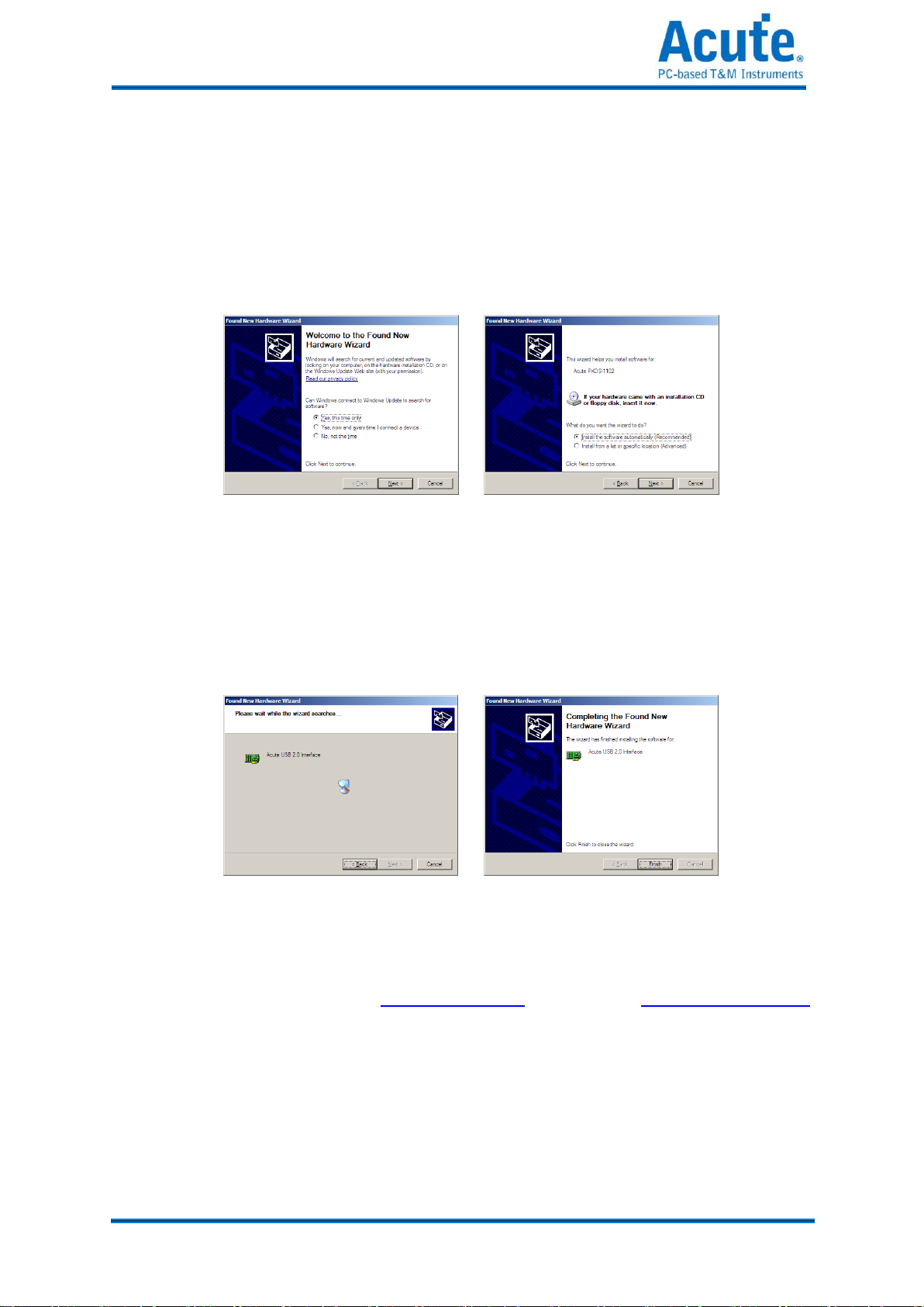
2.1 Installation Procedures
2.1.1 Driver Installation for Windows XP
(1) Insert the installation CD and connect the DS-1000 with your PC.
(2) Enter the hardware wizard when the Windows OS find an USB device (Figure 1)
and check “yes. This time only”.
Figure 1 Figure 2
(3) Choose “Install the software automatically” (Recommended) to find the proper
driver automatically (Figure 2). Click “Next”.
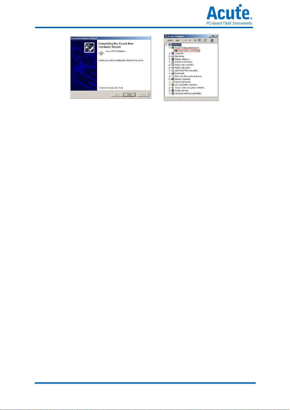
(4) Click “Next” when a driver is found.
Figure 3 Figure 4
(5) You will see the “Acute USB 2.0 Interface” in the Device Manager (Figure 6).
if there is any installation problem.
17
Acute Technology Inc.
Copyright 2012
Figure 5 Figure 6
Other manuals for TravelScope Series
1
This manual suits for next models
1
Table of contents
Other Acute Test Equipment manuals


