SATEL ARF-100 3
– press the button to toggle between simulation of the device powered from an
external source and simulation of the device powered from a battery. After switch-
on the tester simulates operation of the device powered from an external source.
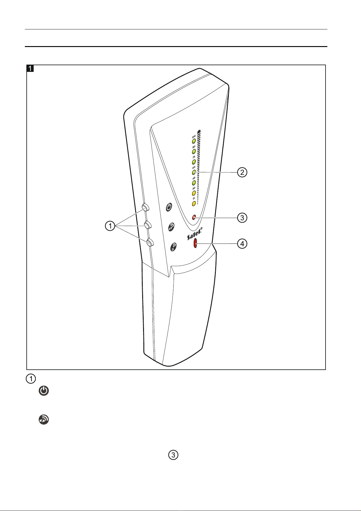
Which power supply method is being simulated is indicated by the LED .
Press and hold down the button to change the refresh rate of the radio signal level
indicator . After switching the tester on, the indicator refresh takes place during
polling and is signaled by one short beep. If you hold down the button longer than
3 seconds, the tester will enter and remain in the dense polling mode until the
button is released. When in this mode, the indicator is refreshed every 2 seconds,
which is signaled by two short beeps.
radio signal level indicator. The indicator consists of 7 LEDs (2 yellow and 5 green ones),
which present percentage of the radio signal level (15 – 100%). Intensity of the LED
lighting depends on which device is simulated by the tester. If a battery-powered device
is being simulated, the LED light is weaker. If, when the LEDs are ON, you change the
power supply method (by pressing the button), the LEDs will go off. They will only go
on again during the next polling and will show an updated radio signal level. If the tester
battery is low, all the indicator LEDs are blinking.
red LED indicating the tester operating mode:
ON – checking the level of radio signal received by the tester from the ABAX
controller / control panel,
flashing – checking the level of radio signal received by the ABAX controller / control
panel from the tester.
red LED indicating how the device being simulated is power supplied:
ON – powered from battery (e.g. AMD-100, AMD-101 and APD-100 detectors,
ASP-205 siren),
OFF – powered from an external source (e.g. ACX-200 expander, ASP-105 siren,
ASW-100 wireless controller).
4. Start-up and testing the radio signal level
There is a danger of battery explosion when using a different battery than
recommended by the manufacturer, or handling the battery improperly.
Be particularly careful during installation and replacement of the battery. The
manufacturer is not liable for the consequences of incorrect installation of the
battery.
The used batteries must not be discarded, but should be disposed of in
accordance with the existing rules for environment protection.
1. Install the battery and switch the tester on.
2. Add the tester to the wireless system (see the manual for ACU-120 / ACU-270 controller
or the installer manual for INTEGRA 128-WRL / VERSA / VERSA Plus / VERSA IP
control panel). The serial number of each tester is 0000500.
3. Use the button to define how the device simulated by the tester is supplied.
4. Start the test mode on the ABAX controller / control panel.
5. Place the tester in the location intended for installation of wireless device and check the
level of radio signal received by the tester from the ABAX controller / control panel and
the level of signal received by the ABAX controller / control panel from the tester. If the