Adam Pumps TECH TANK 210L Guide

cabinets, meter, DC and AC pumps, accessories, repair kit
MANUAL OPERATION AND MAINTENANCE
TECH TANK
210L
440L

NB PERFORMANCE OF UNAUTHORIZED MODIFICATIONS TO
“ADAM PUMPS” AUTOMATICALLY VOID WARRANTY OF ANY AND
ALL RESPONSIBILITY ‘CIVIL AND CRIMINAL CHARGE OF THE
SAME.
GENERAL DESCRIPTION
INSTALLATION & OPERATION
MAINTENANCE & REPAIR
PARTS LIST
Read and understand this Operating Manual before starting
installation, maintenance or repair.
GENERAL DESCRIPTION AND ALLOWED USE
This diesel transfer system is designed for the delivery of diesel fuel
(also for heating fuel and antifreeze) to vehicles and equipment from
an open surface storage tank. The pump is a self priming, positive
displacement, rotary vane machine which operates on 12V DC power
(models for 24V DC power are available), and delivers a flow of
approximately 40 litres per minute. The pump has a built-in bypass
valve that keeps the operating pressure below 1.3 Bar (18 psi). The
motor has a 30 minute duty cycle.
SAFETY PRECAUTIONS AND FORBIDDEN USE
Improper use or installation of this product can
cause serious bodily injury or death!
• Not for use with gasoline, alcohol, or other liquid
with a flash point below 40°C (104°F)
• Not for use in hazardous locations.
• Not for use with fluids thicker than diesel fuel.
• Not for use to transfer fluids into an aircraft.
• Not for use with fluids for human consumption.
• Not for dispensing water.
• Not for continuous duty applications.
EC COMPLIANCE STATEMENT
ADAM PUMPS ITALIA SPA, Via della Resistenza, 46/48,
41011 Campogalliano (Modena) - Italy, states.This system has been
designed for stocking, transport and transfer of diesel fuel for vehicles
or machines (see forbidden use paragraph). The flow comply with
the Directive for Machines 89/392/CEE (91/368/CEE, 93/44/CEE,
93/68/CEE), 89/336/CEE (93/68/CEE), 73/23/CEE, and with stand-
ards EN 60529, EN 60204-1, EN 55081-2. The TECH TANK system
has been designed following total exemption normative 1.1.3.1C
ADR. Declaring that the pump EN 55011C/.A, D.L. 277/91 and
AC Tech 40, conforms to the harmonized EN 60529, EN 60204-1,
EN 50081-2, EN 55011C/.A, DL 277/91. This document has been
signed by:
Mr. Bernard Gilson, Via della Resistenza, 46/48,
41011 Campogalliano (Modena) - Italy, Phone +39 059 528128,
Fax +39 059 528437who has full legal authority to represent the firm
in the European Community. Dated, 1st of February 2008.
Machine Identification - Label (typical example)
This Operating Manual should be considered as part of the
machine. When the machine is sold, it must be transferred
to the new owner.
ADAM PUMPS Italia Spa
Via della Resistenza 48
41011 Campogalliano
Modena Italy
Code : 2108510020802
ELETTR. KPT 12-40 FLT 25 CASS. PL. ROSS
12 Volt - 270 Watt - 18 A - 2800 r.p.m.
30 min. duty cycle Weight Kg.: 4
Manufacturer
Production
date
Product code
Model
Technical
data
2006
NOV
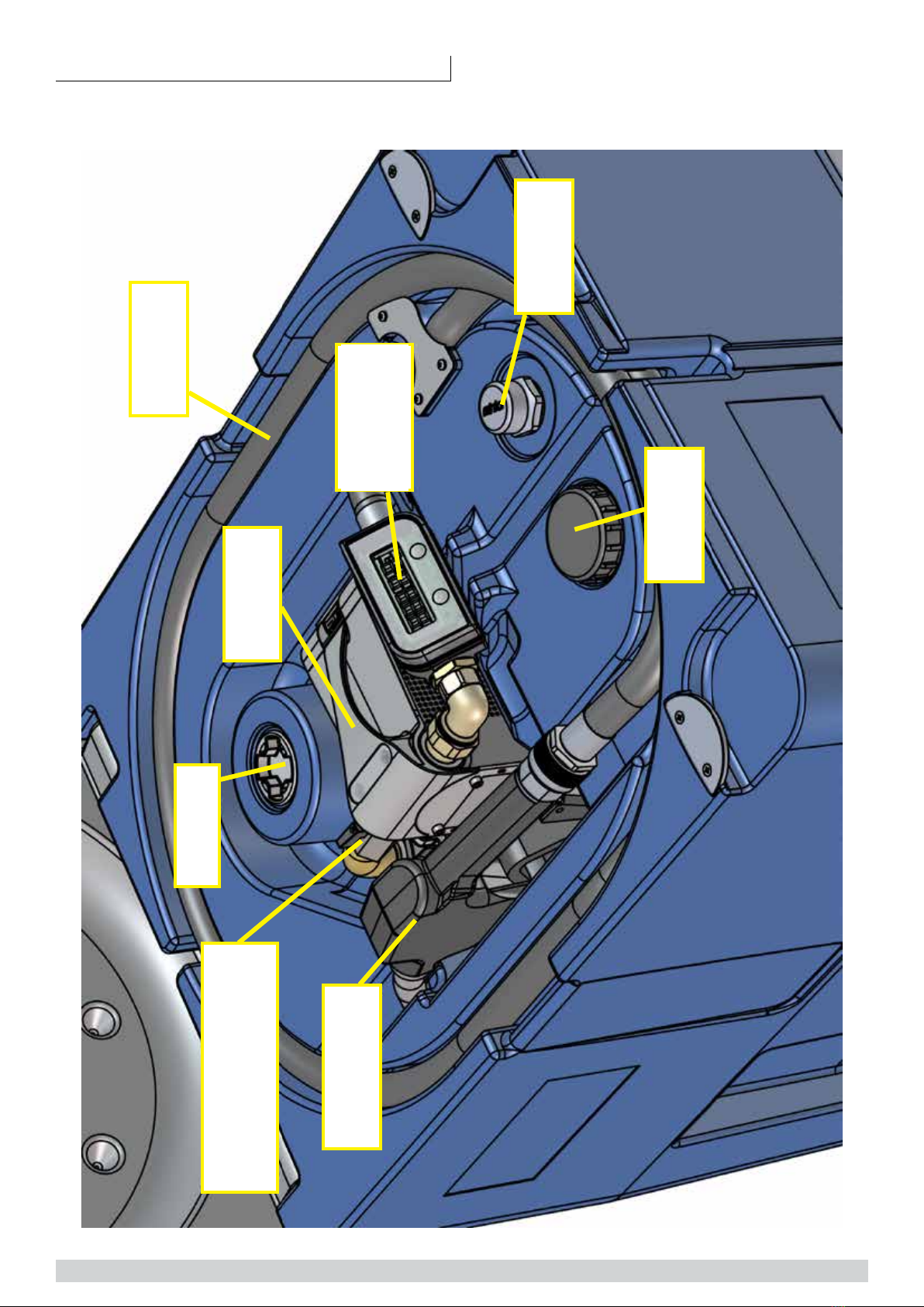
TECH TANK 1
DISCHARGE
HOOSE
C-TECH 40
PUMP
IN-LINE
DIGITAL
FLOWMETER
RELIEF
VALVE
FILLER
PLUG
AUTOMATIC
NOZZLE 60L
CAP 2”
TRANSFER GROUP COMPONENTS
SUCTION
OPENING/CHIUSING
VALVE
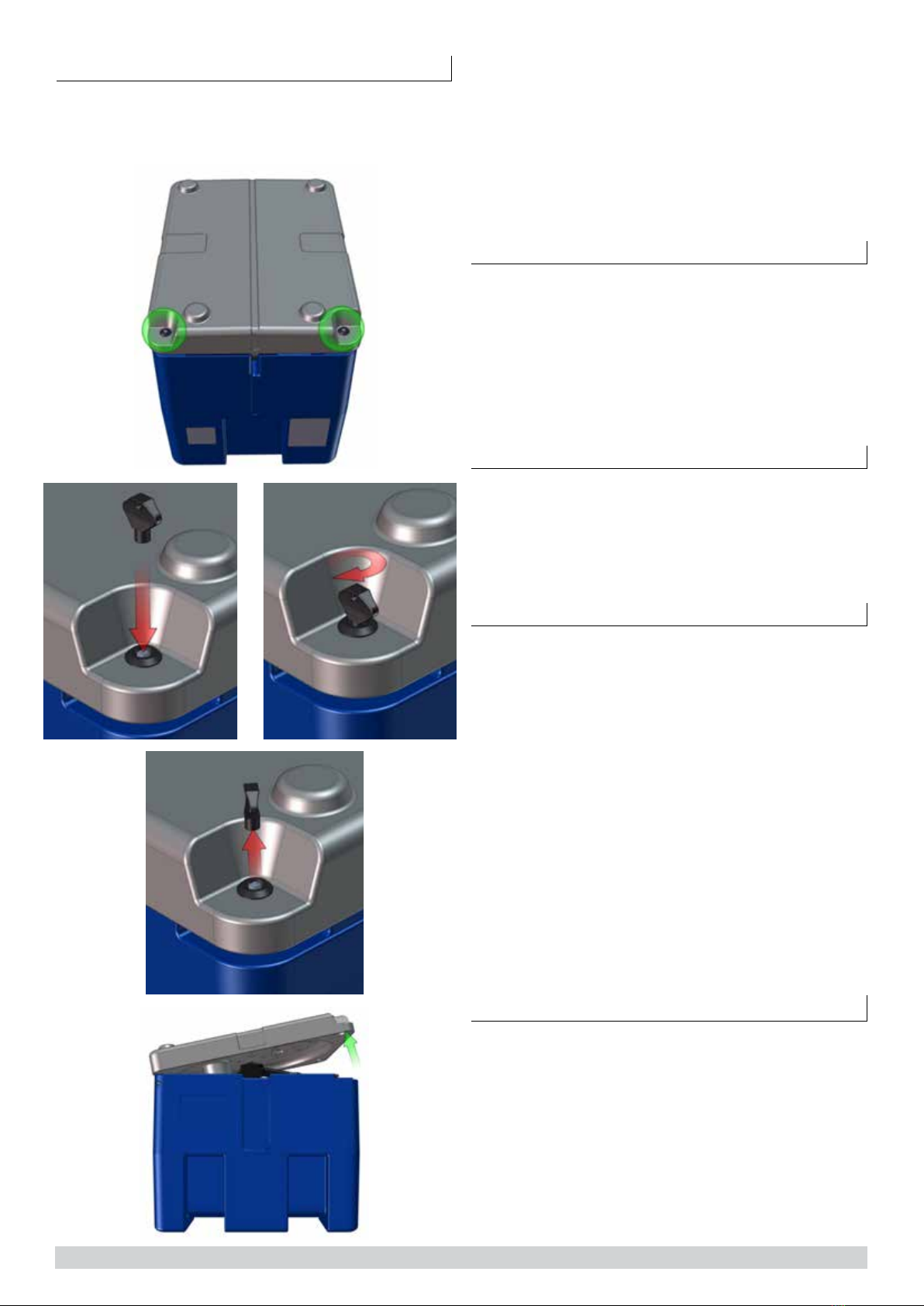
b) Position the tank on a secure surface, in a ventilated area, mak-
ing sure that it is securely fastened during transportation. ATTEN-
TION once full with diesel, the sloshing force could provoke tank
movements!
c) Unscrew the filler plug and fill up the tank with diesel after hav-
ing verified that pump is unplugged. For this operation wear ap-
propriate safety clothes and devices like glasses and gloves.
d) One the tank is full, close and secure the filler plug.
e) If part of the kit, calibrate the digital flowmeter Di-Flow In line.
(CALIBRATION paragraph)
ELECTRICAL INSTALLATION 12/24V
1. Connect the battery clips on the motor power cord to a suitable
battery, capable of delivering the necessary voltage and current
(see the Technical Data, back page of this manual)
• The RED clip is attached to the positive (+) battery terminal.
• The BLACK clip is attached to the negative (-) battery terminal
or to the vehicle frame.
2. If the power cable provided is not long enough, have it replaced
by an authorized electrician.
Avoid sparks that could cause a fire: Do NOT use a
patch cord to extend the power cables.
ELECTRICAL INSTALLATION 230V
The pump must be provided with a safety device of 30mA mini-
mum Din standard. The plug must be connected to an earthed
SHUKO socket. Do not cut or replace the provided plug.
Avoid sparks that could cause a fire: Do NOT use a
patch cord to extend the power cables.
OPERATIONS
AVOID HAVING PUMP RUNNING DRY FOR MORE THAN 3 MINUTES.
a) Open tank cover.
b) Before using the system, clean nozzle and hose from dirt.
c) Insert the nozzle into that to be filled up.
d) Connect the electrical cable to power supply as explained in para-
graph: ELECTRICAL INSTALLATION after having verified that pump
switch is on OFF(O)
e) Open the valve located at pump inlet.
f) Switch on pump motor.
g) Reset the DI-FLOW flowmeter to 0 by pressing the R button
h) Press nozzle lever to dispense.
i) When desired quantity or when the nozzle has automatically
closed, release the trigger.
j) Switch off pump immediately.
k) Reposition nozzle and hose into their login and rewind power
supply cable.
l) Close pump inlet valve and close tank cover.
MAINTENANCE
1. Inspect and clean the strainer on the inlet hose or pipe monthly.
2. Clean the metal “mouth” portion of the battery clips with steel
wool monthly to maintain good electrical connection to the battery.
3. Hoses should be inspected annually. Replace if cracked or worn.
4. Rotor and vanes will eventually wear, and should be replaced if pump
performance degrades. See the “Operational Problems” section to
determine if replacement is needed.
5. Drain hoses and pump and store in a clean, dry place when not in use.
®Teflon is a registered trademark of E.I. Du Pont De Nemours and Company.
PRELIMINARY OPERATIONS
Before making any type of operation, read atten-
tively this manual..
a) Using the key supplied with the unit, open the tank cover,
make sure that during tran sport thank has not been damaged.
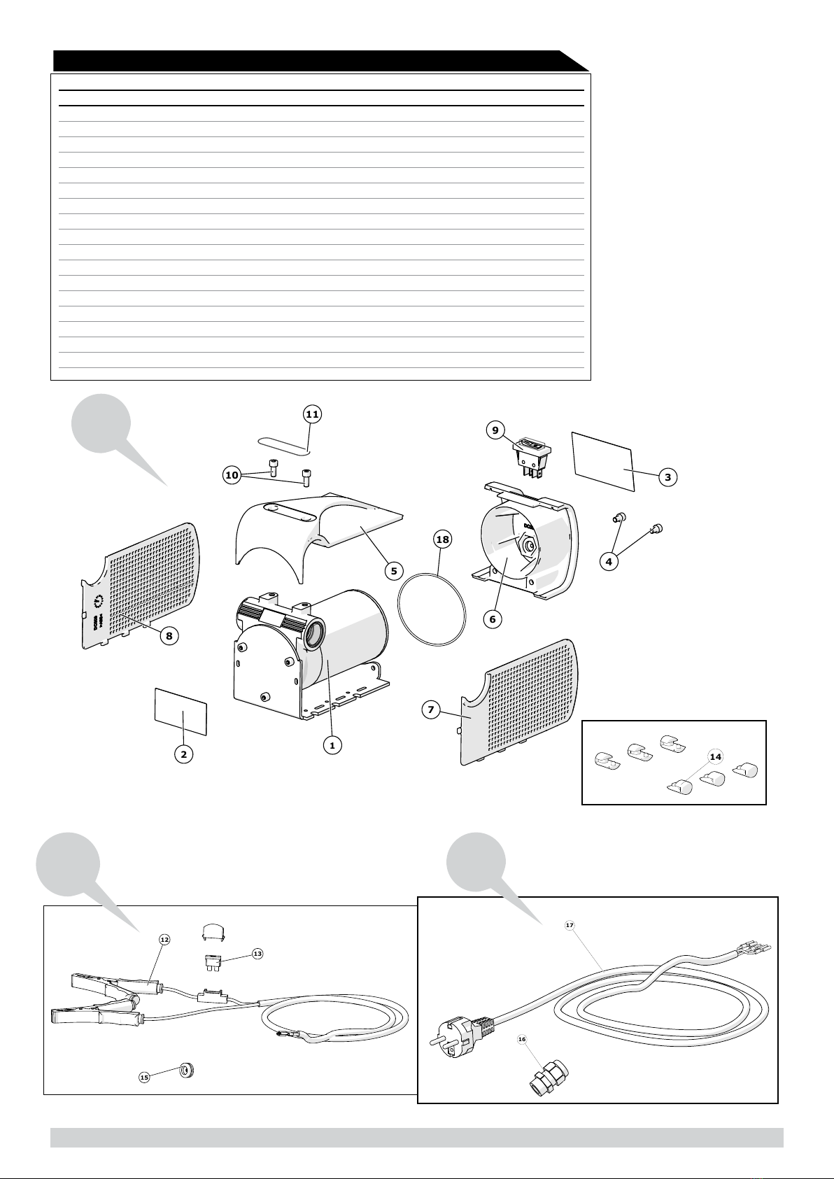
2 TECH TANK •
1. 2.
3.
4.

TECH TANK 3
POS REFERENCE DESCRIPTION Q.TY
1 TT010 TANK 1
2 TT04 RELIEF VALVE1” BSP/G 1
3 OR006 O-RING 4112 1
4 121500700000 FILTER FLT 25 1
5 TUB002 BOCCOLA PRESSATUBO Ø 25 2
6 20152500000 TRANSPARENT SPIRALED HOSE Ø25 PVC 1
7 240015025000 HOSE STEM 1X25 O-RING 3118 NBR 1
8 13001015 SCREW TCCE M8X16 ZNB ISO 4762 2
9 INCH0002 TANK ADAPTOR 2” BSP/G 1
10 18001008 O-RING 3118 NBR 1
11 INCH0034 SWIVEL 3/4” BSP/G 1
12 250151500200 BRASS ELBOW 90° 3/4” BSP-G M-F 1
13 TT008 VALVE 3/4” BSP/G M/F 1
14 - PUMP C-TECH 40 1
AC400200 AC - TECH 40 L 230 V -
DC402400 DC - TECH 40L12V -
DC404400 DC - TECH 40L 24 V -
15 250161500200 BRASS CURVED NIPPLE 3 PZ 3/4” BSP-G 1
16 250053254000 BRASS NIPPLE 1’’-3/4’’M 1
17 ILG00D IN-LINE DIGITAL FLOWMETER 1
18 240015020000 HOSE STEM 1”X19 + O-RING 3118 NBR 2
19 TUB001 ALUMINUM BUSHING Ø19 (B28X30) 2
20 201015005000 DISCHARGE HOSE Ø19 X 4M 1
21 2715010000000 AUTOMATIC NOZZLE 60L 1
SPARE PARTS MANUAL
REPAIR KITS
KIT - 40 KIT40
KIT BY PASS 40-45 KITBY40-45
OPERATIONAL PROBLEMS (See Figures 5, 6 & 7)
Relieve pressure by opening the nozzle and draining the hose, and
disconnect power before servicing pump.
PROBLEM POSSIBLE CAUSE SOLUTION
Pump won’t
prime.
1. Suction line problem
2. Outlet is blocked
3. Bypass valve open
4. Vanes are sticking
5. Excessive rotor
and/or vane wear
Check for leaks or obstruction in suc-
tion hose or pipe;
Check to make sure outlet hose
and nozzle are clear and operating
correctly;
Remove and inspect valve; must
move freely & free of debris;
Check vanes and slots for nicks,
burrs and wear;
Replace rotor and vanes;
Pump hums but
won’t dispense
fluid.
1. Dirt or rust in pump
cavity
2. Broken rotor key
3. Motor failure
Clean out pump cavity;
Remove all debris & replace key;
Return to place of purchase;
Low Flow. 1. Excessive dirt in filter
2. Restriction on the
outlet or in the inlet
3. Excessive rotor or
vane wear
4. Low fluid level
Remove and clean or replace filter;
Long and small ID hoses, filters, and
automatic nozzles will reduce the flow
rate. Use higher flow components;
Replace rotor and vanes;
Fill tank;
Pump runs
slowly.
1. Incorrect voltage
2. Vanes sticking
3. Wiring problem
4. Motor problem
Check incoming power;
Check vanes and slots for nicks,
burrs and wear;
Check for loose connections;
Return to place of purchase;
Motor surface
temperature
gets hotter than
100°C (212°F).
1. Fluid is too thick
2. Motor ran more than
30 minutes
3. Excessive dirt in filter
4. Blocked pump rotor
Fluid must not be thicker than diesel
fuel;
Motor is designed for a maximum
“on” time of 30 minutes. Motor must
be allowed to cool down before using
again (except for model PA1 60);
Remove and clean filter;
Clean and check rotor and vanes;
Motor will not
turn on.
1. Battery dead or low
(pump 12-24V)
2. Fuse in power cord
is blown (pump
12-24V)
3. Switch failure
Check battery;
A blown fuse often indicates a prob-
lem with the free rotation of the mo-
tor. Inspect for dirt or debris in pump
cavity. Replace fuse with a standard
automobile fuse with same value;
Replace switch;
Liquid leaks. 1. Bad o-ring gaskets
2. Dirty shaft seal
3. Bad shaft seal
4. Incompatible fluid
5. Loose fasteners
Check all o-ring gaskets;
Clean seal and seal cavity;
Replace seal;
The liquid must be compatible with
HNBR seals and cast iron;
Tighten fasteners;
NOTICE: ANY MODIFICATION PERFORMED ON THE UNITS WITH-
OUT “ADAM PUMPS” WRITTEN PERMISSION WILL AUTOMATI-
CALLY VOID ANY GUARANTEE AND FREE “ADAM PUMPS” FROM
ANY KIND OF RESPONSIBILITY.

5
8
1
18
4
6
19
5
16
7
2
9
8
3
19
11
10
12
13
20
17
21
18
15
14
4 TECH TANK
TECH TANK

TECH TANK 5
TECHNICAL DATA
GENERAL FEATURES 210L
capacity[L]: 210
dimensions [mm; bxhxp]: 800x600x700
material: polyethylene
empty weight [kg]: 26
empty weight with pump [kg]: 35
cover with locking key: yes
GENERAL FEATURES 440L
capacity[L]: 440
dimensions [mm; bxhxp]: 1200x800x700
material: polyethylene
empty weight [kg]: 45
empty weight with pump [kg]: 54
cover with locking key: yes
TANK
IN RELIEF ADR
N°1.1.3.1.C
VERSIONS
TECH TANK STANDARD 12v CC 24v CC 230v CA
Voltage [V]: 12 24 230
Flow [l/min]: 40 40 40
Cable [m]: 4 4 2
Shut-off valve: sì sì sì
Filler plug: 2” 2” 2”
Discharge hose [m, Ø]: 4.5 - Ø 19 4.5 - Ø 19 4.5 - Ø 19
Nozzle: automatic automatic automatic
Meter: no no no
Safety valve / vent: 1” 1” 1”
TECH TANK TOP 12 v CC 24v CC 230v CA
Voltage [V]: 12 24 230
Flow [l/min]: 40 40 40
Cable [m]: 4 4 2
Shut-off valve: sì sì sì
Filler plug: 2” 2” 2”
Discharge hose [m, Ø]: 4.5 - Ø 19 4.5 - Ø 19 4.5 - Ø 19
Nozzle: automatic automatic automatic
Meter: flowmeter In-Line flowmeter In-Line flowmeter In-Line
Safety valve / vent: 1” 1” 1”

6 TECH TANK
17
Figura 6
X TECH
12/24 - 40
O TECH CC 40 FIG 6
2
13
4
16
3
7
6
12
1
8
9
10
11
12
5
15
14
4
REPAIR KIT (see picture 6)
POS. DESCRIPTION CODE QTY
KIT 40 LT KIT40
9 O-RING 2212 1
10 PLASTIC KEY 1
12 VANE 5
8 SEALING RING 10 X 19 X 7 HNBR 1
KIT BY PASS 40-45 LT 41071000
7 VALVE 1
5 BY PASS CAP 1
6 BY PASS SPRING 1
POS. DESCRIPTION CODE QTY
12 V 24 V
1 PUMP HOUSING 40L CP001 CP001 1
2 ELECTRIC MOTOR Ø77 231501700000 231501700000 1
3 PLATE AC-DC TECH 40 DC006 DC006 1
4 SAVE CAP THREAD Ø25 163013300000 163013300000 2
5
BY PASS CAP 71000521 71000521 1
6 BY PASS SPRING Ø21, 4X42 71008006 190110000000 2
7 BY PASS VALVE 71000520 71000520 1
8 SEALING RING Ø19 12010031000 12010031000 1
9 O-RING 2212 NBR 18001014 18001014 1
10 PLASTIC KEY 71000517 71000517 1
11 ROTOR Ø45 61000003 61000003 1
12 VANE 71000522 71000522 5
13 TIE M5 X 115 FLANGED 6100481150 6100481150 2
14 SCREW TCCE M5X112 ISO 4762 13001013 13001013 1
15 STICKER “CE” - - 1
16 STICKER “DANGER” 71000653 71000653 1
17 FOOT AC-DC TECH 40 DC005 DC005 6
TECH TANK 7
4
3
6
9
8
1
5
10
18
11
2
7
AC-DC TECH 40 FIG 7
Figura 7
AC -DC TECH 40
12/24 - 230
14
12
13
15
Figura 8
DC TECH
12/24 - 40
17
30
16
Figura 9
AC TECH
230 - 40
POS. DESCRIPTION CODE QTY
12 V 24 V 230V
1 PUMP O-TECH 40 OT40200 OT40400 OT400000 1
2 STICKER “CE” - - - 1
3 STICKER “DANGER” 71000653 71000653 71000653 1
4 SCREW TCCE M5X8 TRILOBATE DIN 7500 E VT002 VT002 VT002 2
5 HANDLE AC-DC TECH 40 DC001 DC001 DC001 1
6 SWITCH HOLDER AC-DC TECH 40 DC002 DC002 DC002 1
7 RIGHT SIDE AC-DC TECH 40 DC004 DC004 DC004 1
8 LEFT SIDE AC-DC TECH 40 DC003 DC003 DC003 1
9 SWITCH ON/OFF 11X30 190050070000 190050070000 190050070000 1
10 SCREW TCCE M5X12 ISO 4762 13001013 13001013 13001013 2
11 FACEPLATE AC-DC TECH 40 MA022 MA022 MA023 1
12 CABLE WITH CLAMP 2M (FIG 8) 17001010 17001010 - 1
13
FUSIBLE 30A (
FIG 8)
190170150000 190170150000 - 1
14 FOOT AC-DC TECH 40 DC005 DC005 DC005 6
15
CABLE GROMMET
(FIG 8) 190100100000 190100100000 - 1
16 CABLE GROMMET (FIG 9) - - AC001 1
17 CABLE WITH SCHUKO PLUG (FIG 9) - - 19000000000 1
18 O-RING 2287 NBR - - OR010 1
8 TECH TANK
5. DI FLOW DIGITAL METER; DI FLOW IN-LINE DIGITAL FLOW METER
3. INSTALLATION AND USE
3.1 DISPLAY ORIENTATION
The meter is supplied with a calibration carried
out for liquid diesel at 20 °C. Calibration is
required when metering a different fluid, after
disassembly, at different temperature or after
significant wear. A proving container or a con-
tainer of KNOWN volume will be needed for the
calibration procedure. It is possible to invert the
flow direction using following steps:
1. Remove the 4 screws from the back of the
meter
2. Rotate the meter body by 180°
3. Reposition the body on the cover taking care of
not squeezing wires.
4. Screw the 4 screws to tighten the body to the
cover.
3.2 CONNECTIONS
When adding the flow meter to a existing sys-
tem, connect the flow meter inlet to the outlet
at of the pump, and connect the delivery
hose into the flow meter outlet. It is important
to respect the flow direction looking at the arrows
on the meter body. In case you need the opposite
flow, rotate the meter as described above in para-
graph 3.1.
The meter has a double Reed switch system to
avoid false readings due to vibrations or erroneous
installation and turbine reverse rotation. The meter
is threaded 1” BSP-P female both at inlet and out-
let. Sealing is made using O - ring 30x3 70Sh.
1
2
3
2.5
It is necessary, if not already installed in the
system, to install a filter or screen of at least
40 mesh prior to the flow meter.
3.2.1 ELECTRICAL WIRING FOR PULSER
VERSION
If you bought our pulser model, the flowmeter is
fitted with a 2m cable with 5 internal wirers to be
connected as follows:
1. Yellow wire: power + 12 Vdc
2. Brown wire: power 0 Vdc
3. Green wire: pulser channel 100 imp/unit
4. White and grey wires: Relay contact should you
desire to control the pump with the meter ( max
24Vdc 500mAh)
Once connected to power supply, the meter will
“Beep”, this sound beeps at each button pressure
(this happens only with pulser version).
It is important to know that the system is genera-
ting pulses 0-12Vdc with maximum frequency 2
milliseconds.
Should the meter control the pump, the button
will activate the pump while button stops it.
Two default settings are available and settable in
the system:
1. 60 seconds: to start the transaction after pres-
sing button
2. 20 seconds: seconds without pulse will stop the
transaction.
TECH TANK 9
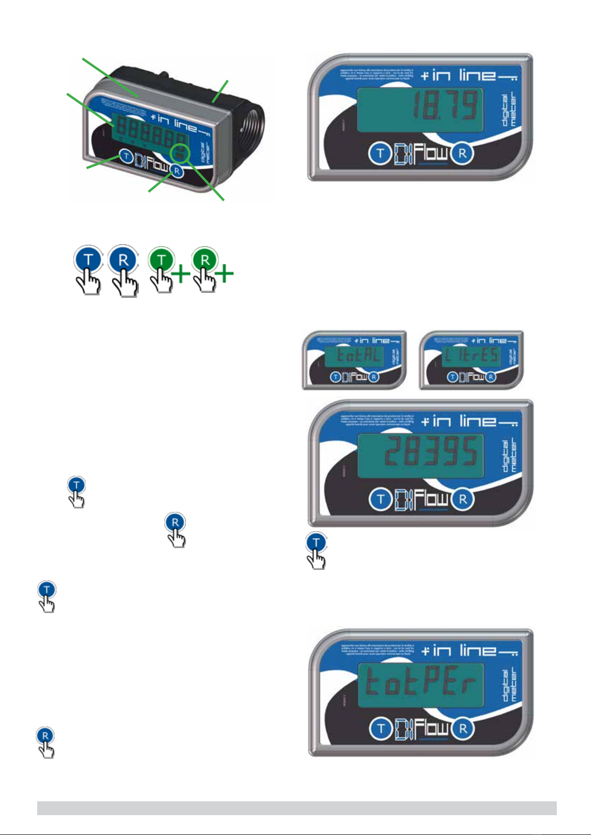
3.3 KEY DISPLAY
3.4 MAIN FUNCTIONS
The meter switches on automatically when a
transaction starts or when a button is pressed.
The display switches off automatically when no
transaction nor pulse is being detected during 120
seconds. Each time the display switches off, the
“partial” resets to “0”. It is then not necessary to
reset the meter after it has switched off. When the
meter switches o, it will automatically show the
“partial” counter, it will also go back to this screen
if buttons are not pressed during 10 seconds.
There are 5 main screens that can be scrolled
using button, last 5 transaction however
could be visualized using button.
3.3.1 SIMBOLS
simple pressure continued pressure
Starting from the “Partial” screen and at each time
button is pressed, system will scroll between
last 5 transactions. To go back to “partial” screens
wait 10 seconds without pressing buttons.
3.4.0 SCROLLING THROUGH 5 MAIN SCREENS
Starting from the “Partial” screen and at each time
button is pressed, following screens sequence
will be displayed:
1)ToTal, preceded by message “Total Litres”
2)ToTal period, preceded by message “TotPer”
3)Tank STock, preceded by message “Stock”
4)MiniMuM STock alarM, preceded by message
“Alert”
5)parTial
body
cover
“total”
button
display
“reset”
button
battery
alter
simbol
3.4.1 “PARTIAL” SCREEN
3.4.3 “TOTAL PERIOD ”SCREEN WITH
MESSAGE ”TOTPER”
3.4.2 “TOTAL” SCREEN WITH MESSAGE “TO-
TAL LITRES””
Displays 4.2 digits, switches on while pressing a
button or detecting pulses at transaction start. An
active meter will go back to this screens after 10
seconds without activity.
This screen is used as initial condition to
describe other 4 available screens:
, displays 6 digits, no decimal, shows all litres
transferred since first use. Cannot be reset.
10 TECH TANK
displays 5.1 digits, identifica shows all
litres transferred in a defined period of time. This
totalizer can be reset by pressing button.
displays 5 digits, no decimal,
shows the calculated available stock. To insert
available stock, it is necessary to go to “Stock”
screen and press button. Value on display will
start blinking and will be then modifiable, increa-
sing the value pressing button or decreasing
it pressing button until you reach the desired
number. Should you maintain the button pressed,
the value will change rapidly. To confirm, wait 10
seconds until the “partial” screen I displayed.
3.4.4 “TANK STOCK” SCREENS WITH
MESSAGE ”STOCK””
displays 5 digits, no decimal
place, settable at maximum 65000 litres. Such
number identifies the minimum stock in the tank
under which the meter will display the alarm. To set
this alarm level, go to “Alert” screens and press
button . Value on display will start blinking and will
be then modifiable, increasing the value pressing
button or decreasing it pressing button until
you reach the desired number. Should you main-
tain the button pressed, the value will change rapi-
dly. To confirm, wait 10 seconds until the “partial”
screen I displayed.
NB. Setting the value “0”, alarm will be de-activa-
ted.
3.4.5 “MINIMUM STOCK ALARM” SCREEN
WITH MESSAGE ”ALERT”
3.4.6 “LAST TRANSACTIONS SCREENS”

Scrolling using but
ton, displays 4.2 digits, allows you to see last 5
transactions. Each time button is pressed,
display shows the transaction number and the
amount transferred. It is possible to sum the last
transactions by pressing button. Total is
made depending off in which screens we currently
are, example if we are currently displaying the four-
th transaction, pressing button will T-04
and the sum of the 4 preceding transactions. It is
possible to do this in any position of the tran-
sactions history.
3.5 SECONDARY FUNCTIONS
The device has some secondary function, neces-
sary to the good operation of the meter which are:
calibration, unit selection and instantaneous flow
rate.
3.5.1 CALIBRATION
The meter is supplied with a pre-calibration car-
ried out for liquid diesel at 20 °C. Calibration is
required when metering a different fluid, after dis-
assembly, at different temperature or after signif-
icant wear. A proving container or a container of
KNOWN volume will be needed for the calibration
procedure. It is recommended that the container
volume be at least 19 liters (5 gallons).
18
16
14
12
16 18,5
ATTENTON: the system does not allow a cali-
bration if quantity transferred is under 5 litres.
Calibration procedure
1. Starting from “Partial” screen, fill up the calibra-
tion jug to a known volume; it is important to do
this at a flow rate of minimum 10 litres a minute
without topping up else calibration could be inac-
curate. Use the nozzle fully open.
2. if the displayed quantity is not matching the me-
asured quantity the meter must be calibrated.
3. to enter in calibration mode, display will
show “CAL” blinking
4. to confirm, will display last quantity
transferred blinking in current unit
of measure
5. Increase or decrease that quantity using
or
buttons until correct quantity i displayed.
6. Wait 10 seconds to confirm and save automati-
cally this new calibration.
TECH TANK 11
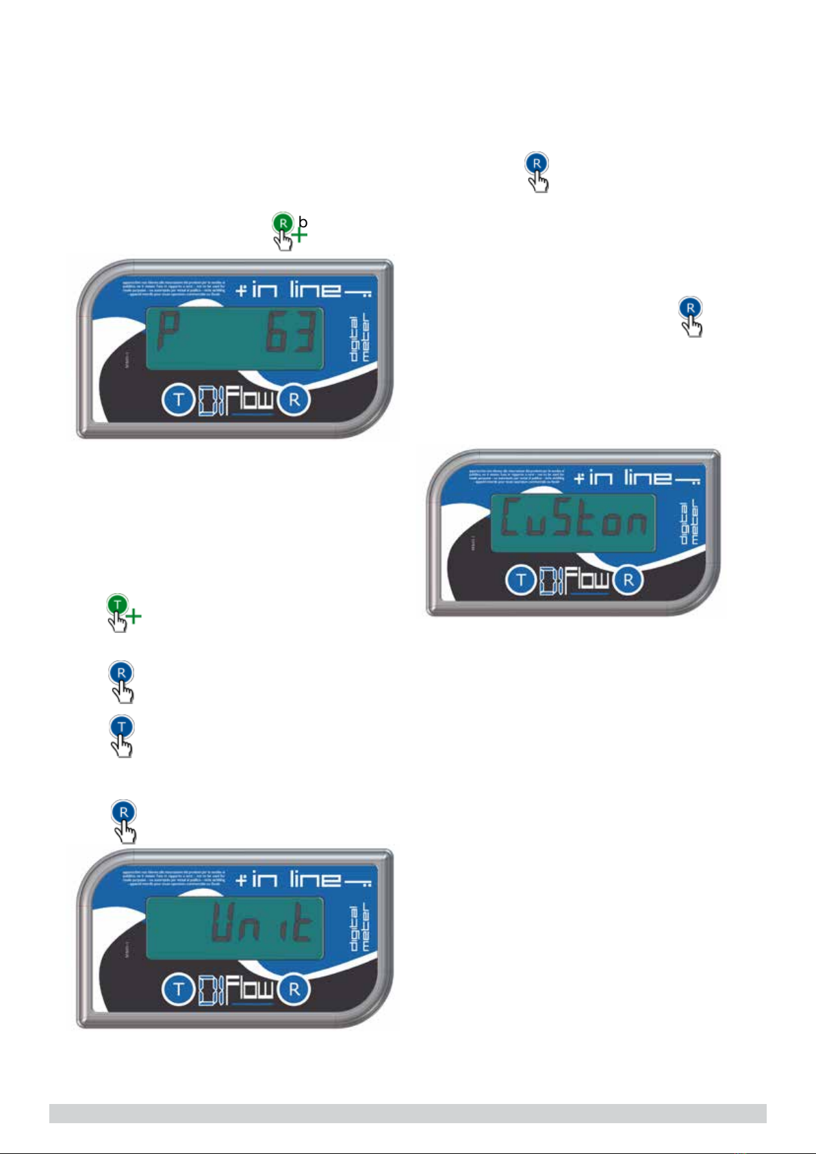
3.5.3 SELECTING UNIT OF MEASURE
The system has 4 standard units of measure (Litre
- US Gallon - Quarts & Pint) plus one “Custom”
unit that can be configured by the user. To select
the unit, do as follows:
1. Start from “Partial” screen, to do this do not
press buttons for 10 seconds.
2. press to enter in “unit of measure” mode,
the message “Unit” will be displayed
3. press to confirm
4. press to scroll between unit:
“litres”- “us-gal” –“quarts” – “pints” – “custom”
5. press to confirm.
3.5.2 INSTANTANEOUS FLOW RATE
The device is capable of showing the instanta-
neous flow rate during a transaction. To visualize
the flow rate press and maintain button during
transaction.
With this new calibration last transaction as well as
last 5 in history will be adapted to new calibration.
TOTAL and TOTAL PERIOD will remain unchan-
ged.
CUSTOM UNIT OF MEASURE
Default factory setting is decalitre (1/10 litre). This
value can be configured as follows:
1.Repeat operations 1 to 5 from paragraph 3.5.3
“Selecting unit of measure”.
2.Once the choice of “custom” has been confir-
med pressing button, the meter will propose
the default value blinking 0.100. To obtain such a
coefficient, it I necessary to simply divide
“custom”/”litre”. Example: if we desire to have a
“custom” unit (1,00) for a 0,33 litre can, we have to
divide 1 / 0,33 = 3,03 and insert the new coeffi-
cient 3.03.
3.Increase or decrease this value with and
button until you reach the desired value taking into
account that reference unit is the litre.
4. Once the correct value is displayed wait 10
seconds, the meter will save the value and return
to “Partial” screen.
3.5.4 BUTTONS COMBINATIONS:
Starting from “Partial” screen:
(see table page 9)
12 TECH TANK

reset partial screen (only if transaction is not going on
visualize the instantaneous flow rate (only when transaction is ongoing)
visualize first transaction in history
visualize second transaction in history
visualize third transaction in history
visualize fourth transaction in history
visualize fifth transaction in history
visualize first transaction in history
visualize total of first two transactions in history
visualize total of first three transactions in history
visualize total of first four transactions in history
visualize total of all transactions in history
visualize total “Total”
visualize period total “totPer”
reset period total ”totPer”
visualize the ”Stock” situation
modify the value in “Stock”
visualize minimum stock level “Alert”
modify minimum stock level “Alert”
modify “unit of measure”
enter in “calibration mode”
BUTTONS FUNCTION
TECH TANK 13
4. MANUTENTION & STOCK
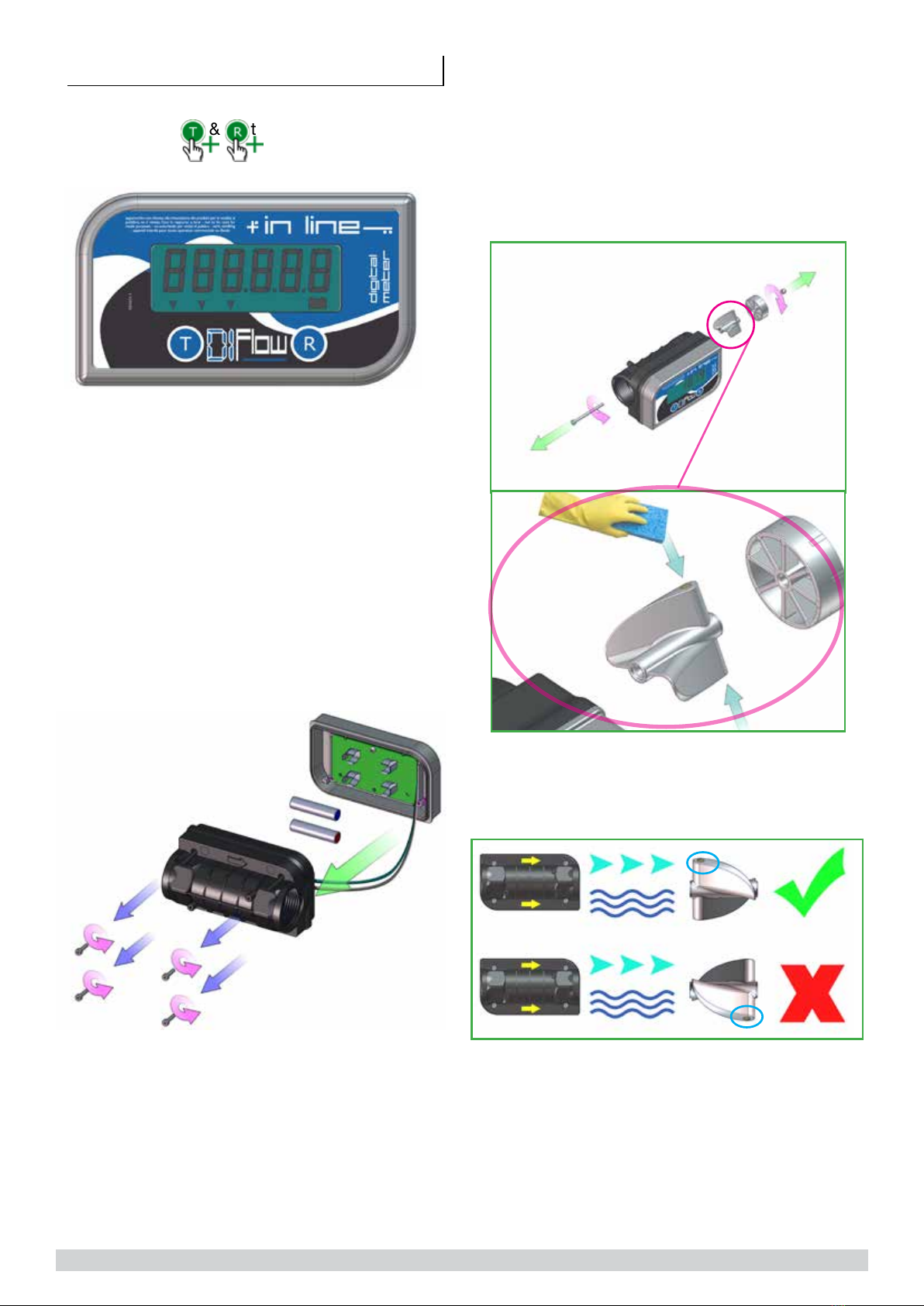
4.1 TEST LCD & BATTERY CHANGE
While pressing & together for 2 seconds,
the system will run a test one the LCD display
The system will then show following information:
1. Product name: ”DI FLOW”
2. Firmware version: “r1.0”
3. Current unit of measure: “Unit” “Litres”
4. Current calibration factor (imp/l): ”CAL” “40.00”
5. Power supply in Volt: “bat Vol” “2.79” (if value is
< di 2.8V else “FULL”)
6. Percentage of residual battery charge: “bat Per”
“52.95”(displayed only if supply tension is < 2.8
Volt)
When battery power is < 0.9Volt the displays
shows a battery icon (bottom left). When this
happens, display brightness will be low. It will be
necessary to change batteries:
1. Rimove the 4 screws on the back of the meter
2. Exchange the 2 batteries with 2 AAA 1.5V alkali-
ne batteries
3. Reposition the body on the cover taking care of
not squeezing wires.
4. Screw the 4 screws to tighten the body to the
cover.
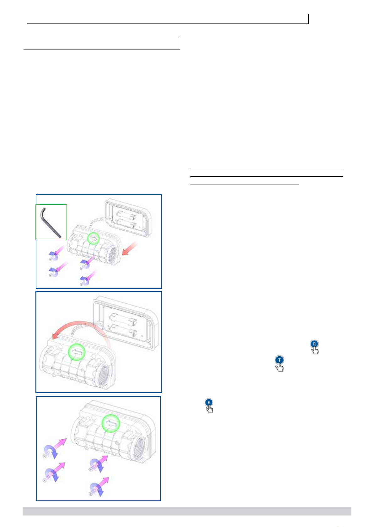
4.2 CLEANING THE TURBINE
The meter has 2 magnets fitted into the turbine.
This magnets could attract metallic powders (if
present) that could block the turbine into the meter
body. For that reason, it could be necessary to pe-
riodically verify and eventually clean the magnets.
To do this, unscrew the internal shaft and its bolt.
Take care to reassemble the turbine in the correct
mode as illustrated hereafter. .
Be careful when reassembling the turbine in the
correct direction, as in the following figure:
14 TECH TANK

5 .TECHNICAL DATA BATTERY
MODEL
1. Measuring system: Turbine
2. Inlet/Outlet : 1” BSP/G female
3. Measuring range: 5 - 150 lpm
4. Accuracy ± 0.5%
5. Repeatability (typical): ± 0.3%
6. Max Pressure of use: 3,5 bar (50 psi)
7. Temperature of use: -10°C + 60°C
8. Display: 6 digits LCD
9. Power supply: Alkaline batteries 2x1.5V AAA
10. Impermeability rating: IP65
11.Weight: 0.25Kg
4.4 DIAGNOSTIC
PROBLEM
The meter is not
reading
The display is
not switching on
Inaccurate preci-
sion reading
POSSIBLE CAUSE
1. turbine is blocked
2. wrong installation
3. Reed switches are
broken
4. turbine has been
reassembled reverse
1. exhausted batteries
2. bad contact on bat-
teries
1. flow rate too low or
too high
2.wrong calibration
3.air inside system
4. dirty magnets
SOLUTIONS
1. Disassemble &
clean turbine
2.verify thanks
to the arrow on
the meter that it
i correctly fitted
on the line.
3. contact your
supplier to get an
Exchange board
4. rotate the
turbine by 180°
1. change bat-
teries
2. verify batteries
positioning
1. verify technical
data on pump
flow rate
2.calibrate
3. verify that
pump is not
sucking air
4. clean magnets
4.3 STOCK
If the meter has to be positioned in stock for a
while, clean it carefully. This will help to prevent
eventual damages.
5 .TECHNICAL DATA DI-FLOW
12V PULSER MODEL
1. Measuring system: Turbine
2. Inlet/Outlet : 1” BSP/G female
3. Measuring range: 5 - 150 lpm
4. Accuracy ± 0.5%
5. Repeatability (typical): ± 0.3%
6. Max Pressure of use: 3,5 bar (50 psi)
7. Temperature of use: -10°C + 60°C
8. Display: 6 digits LCD
9. Connection cable antiflame: 2m
10. Power supply: 12vDC - 10mAh (yellow +12,
brown 0v)
11. Relay contacts: max.voltage 24vdc 500mAh
(white,grey)
12. Pulser output: 0-12vDC, 100 imp/unit (green)
13. Impermeability rating: IP65
14. Weight: 0.25Kg
TECH TANK 15

03.2014 rev. 0
6 . EXPLODED VIEW & SPARE PARTS
POS. DESCRIPTION REF. Q.TY
1 STICKER WITH BUTTONS MA031 1
2 BOLT M3 81101010000 4
3 METER COVER TF035 1
4 ELECTRONIC PCB TF046 1
5 SCREWS M3 VT010 1
6 BATTERY AAA TF048 2
7 O-RING OR018 1
8 BODY DIFLOW – INLINE TF036 1
BODY DI FLOW - INLINE UREA TF042 -
9 TURBINE SHAFT TF039 1
10 TURBINE HOLDER TF038 2
11 TURBINE TF037 1
12 MAGNET TF040 2
13 SELF BLOCKING BOLT VT009 1
14 SCREW M3 X 12 VT011 1
16 TECH TANK
This manual suits for next models
1
Table of contents
Popular Tank Equipment manuals by other brands

AEROTECNICA COLTRI
AEROTECNICA COLTRI COLTRI SUB Instructions for use

Vmac
Vmac A500245 installation manual

Franklin Fueling Systems
Franklin Fueling Systems UPP PIPING installation guide

JohnDow Industries
JohnDow Industries JDI-FST15 user manual

Reverso
Reverso AFP-150 manual

Armstrong
Armstrong 180-LD instructions


