8
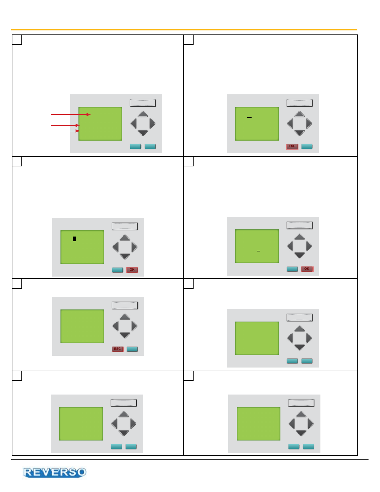
Digital Timer Instructions: Set Schedule Timer
ESC OK
MTWTFSS
MTWTFSS
11:00
15:00
ON
OFF
1 2
3 4
5
7
6
8
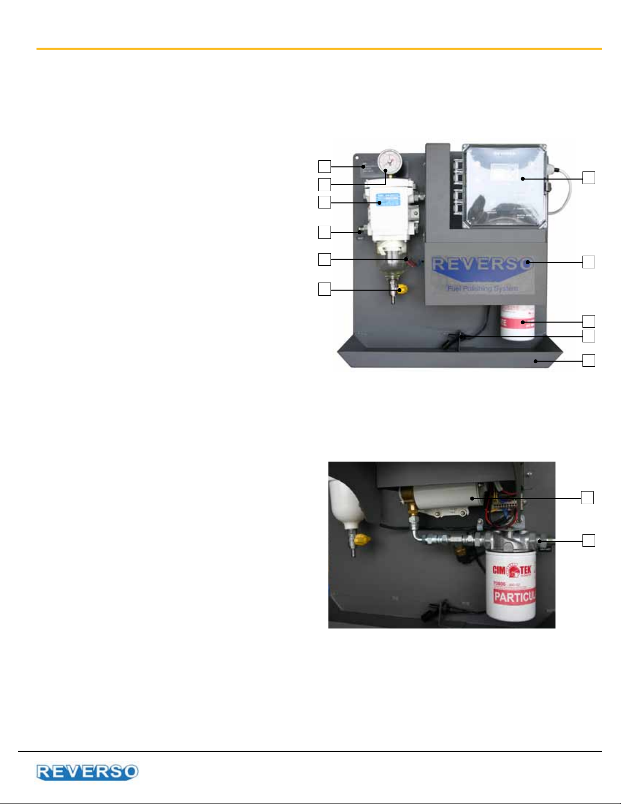
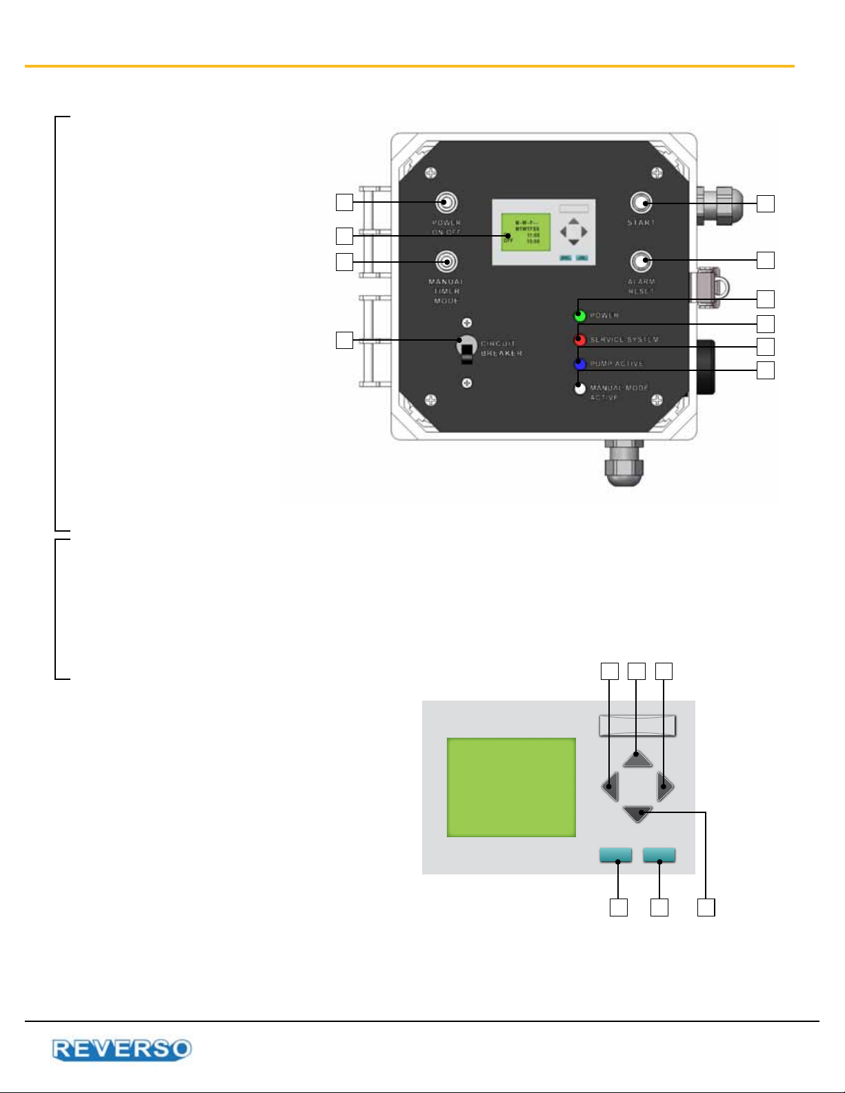
A. Ensure the breaker is ON.
B. Move the red power switch to the ON position and
power indicator light is on.
C. Ensure timer mode is switched to Schedule Timer.
Change the run days
With the ashing underline in the days row, press the
OK key until ashing box appears. Use the LEFT/
RIGHT key to move between days. Use the UP/
DOWN key to program run days. A dash(-) indicates
the system will not run on that day. Press OK key when
nished and the cursor will return to ashing underline.
Press ESC to save. Flashing underline will disappear.
Every 5 seconds, screen will request user to push
Start button to activate pogram.
Hold the ESC key until ashing underline appears
under the rst day of the week. This ashing
underline indicates your selection. Use the LEFT/
RIGHT keys to move between the dates, start time,
and stop time.
When using this method, follow sequence
exactly or damage to program can occur (non-
warrantable situation).
Change the run time
With the ashing underline in the days row, use the
LEFT/RIGHT key to move to start time (ON).Press OK
key until ashing box appears. Use UP/DOWN key
to change time. Press OK key when nished and the
cursor will return to ashing underline. Repeat with
stop time (OFF).
Setting the schedule timer is nished. In this example,
system will run on Monday, Wednesday and Friday.
System will start at 8:00 am and stop at 2:00 pm.
Afterwards, every 5 seconds screen will indicate the
schedule timer is active.
Stop Time
Start Time
Run Days
ESC OK
MTWTFSS
MTWTFSS
11:00
15:00
ON
OFF
ESC OK
M- W - F - -
MTWTFSS
11:00
15:00
ON
OFF
ESC OK
M - W - F - -
MTWTFSS
08:00
14:00
ON
OFF
ESC OK
M - W - F - -
MTWTFSS
08:00
14:00
ON
OFF
ESC OK
M - W - F - -
MTWTFSS
08:00
14:00
ON
OFF
ESC OK
Automatic
Timer
Active
ESC OK
To Activate
Push the
Start
Button