Contents
Introduction ...........................................4
Safety ................................................5
- General information. . . . . . . . . . . . . . . . . . . . . . . . . . . . . . . . . . 5
- Intended use . . . . . . . . . . . . . . . . . . . . . . . . . . . . . . . . . . . . . . . 6
- Wiring, screening, earthing . . . . . . . . . . . . . . . . . . . . . . . . . . . . 7
- Electrical safety . . . . . . . . . . . . . . . . . . . . . . . . . . . . . . . . . . . . . 7
Installation ............................................8
- Location and climatic conditions . . . . . . . . . . . . . . . . . . . . . . . . 8
- Unpacking and storage . . . . . . . . . . . . . . . . . . . . . . . . . . . . . . . 8
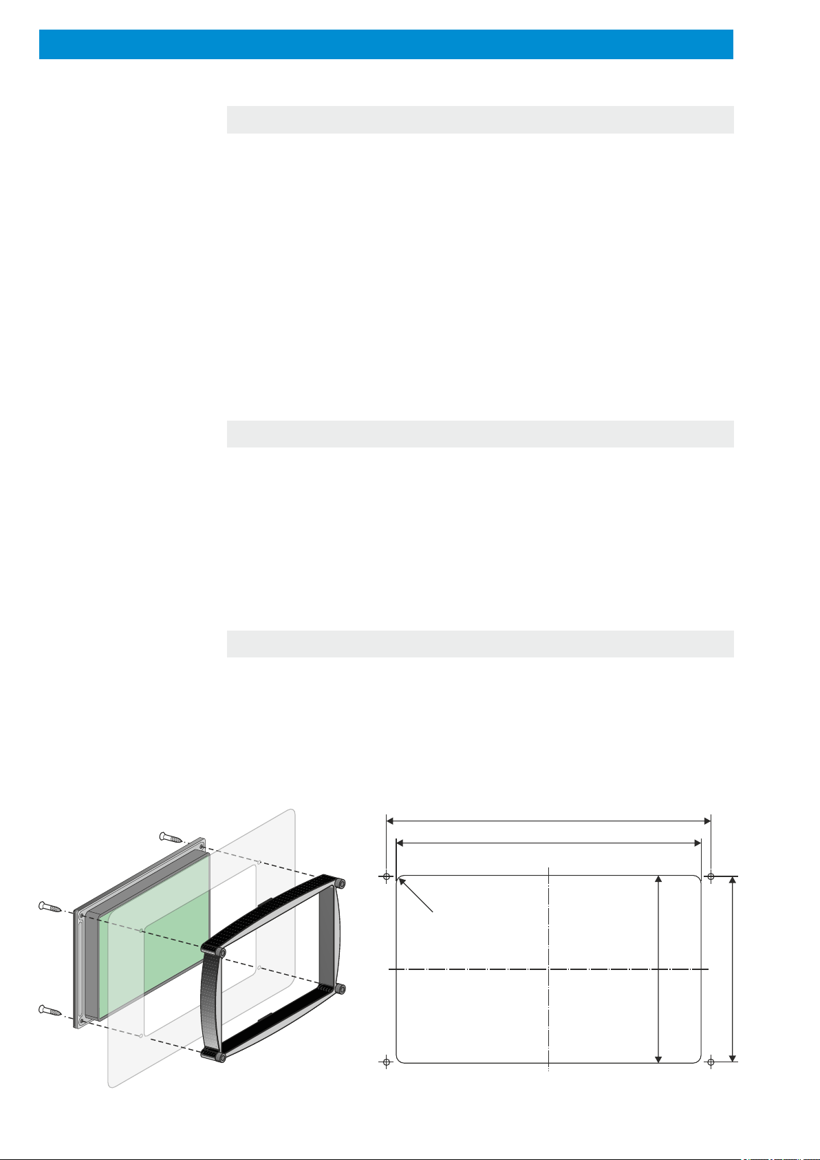
- Installation of housing . . . . . . . . . . . . . . . . . . . . . . . . . . . . . . . . 8
- Fitting the sensor. . . . . . . . . . . . . . . . . . . . . . . . . . . . . . . . . . . . 9
Electrical connection . . . . . . . . . . . . . . . . . . . . . . . . . . . . . . . . . . 10
- Safety during installation. . . . . . . . . . . . . . . . . . . . . . . . . . . . . 10
- Wiring . . . . . . . . . . . . . . . . . . . . . . . . . . . . . . . . . . . . . . . . . . . 10
- Connection diagramm . . . . . . . . . . . . . . . . . . . . . . . . . . . . . . . 11
Technical data ........................................12
Function overview. . . . . . . . . . . . . . . . . . . . . . . . . . . . . . . . . . . . . 14
- Internal data storage . . . . . . . . . . . . . . . . . . . . . . . . . . . . . . . . 15
- EMAIL or SMS- alarm message/remote maintenance/
remote diagnosis . . . . . . . . . . . . . . . . . . . . . . . . . . . . . . . . . . . 15
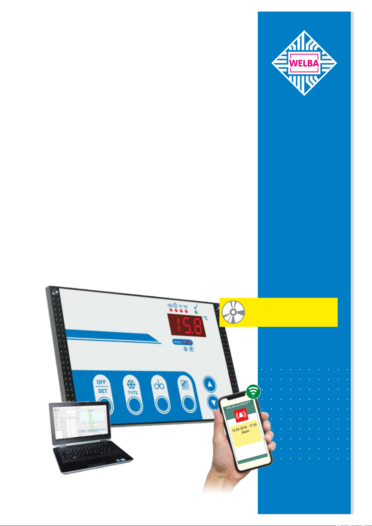
The configuration software "Konsoft" . . . . . . . . . . . . . . . . . . . . 16
Operating levels . . . . . . . . . . . . . . . . . . . . . . . . . . . . . . . . . . . . . . 17
Operation of working level . . . . . . . . . . . . . . . . . . . . . . . . . . . . . . 18
- Button functions . . . . . . . . . . . . . . . . . . . . . . . . . . . . . . . . . . . 18
- Meaning of LEDs. . . . . . . . . . . . . . . . . . . . . . . . . . . . . . . . . . . 20
- Operating modes. . . . . . . . . . . . . . . . . . . . . . . . . . . . . . . . . . . 21
- OFF mode . . . . . . . . . . . . . . . . . . . . . . . . . . . . . . . . . . . . . . 21
- Cooling mode . . . . . . . . . . . . . . . . . . . . . . . . . . . . . . . . . . . . 22
- Cleaning mode . . . . . . . . . . . . . . . . . . . . . . . . . . . . . . . . . . . 23
Contents
Cleaning programme description . . . . . . . . . . . . . . . . . . . . . . . . 24
- Cleaning programme diagram. . . . . . . . . . . . . . . . . . . . . . . . . 24
- Cleaning stages . . . . . . . . . . . . . . . . . . . . . . . . . . . . . . . . . . . 25
- Cleaning with alkaline or acidic detergent. . . . . . . . . . . . . . . . 31
- Disinfect with "P-acid" . . . . . . . . . . . . . . . . . . . . . . . . . . . . . . . 31
- Time of dosing. . . . . . . . . . . . . . . . . . . . . . . . . . . . . . . . . . . . . 31
- Cleaning cycle completed . . . . . . . . . . . . . . . . . . . . . . . . . . . . 32
- Manual stop of the cleaning . . . . . . . . . . . . . . . . . . . . . . . . . . 32
- Stop of the cleaning process due to faults . . . . . . . . . . . . . . . 32
- Power failure during the cleaning process . . . . . . . . . . . . . . . 33
- Quickwash. . . . . . . . . . . . . . . . . . . . . . . . . . . . . . . . . . . . . . . . 33
- Start options for the cleaning process. . . . . . . . . . . . . . . . . . . 33
- Single step function during cleaning . . . . . . . . . . . . . . . . . . . . 34
Adjustment of parameters in general . . . . . . . . . . . . . . . . . . . . . 35
Operation of 'Cooling parameters 1' level . . . . . . . . . . . . . . . . . 36
Operation of 'Cooling parameters 2' level . . . . . . . . . . . . . . . . . 38
Operation of 'Cleaning parameters 1' level. . . . . . . . . . . . . . . . . 44
Operation of 'Cleaning parameters 2' level. . . . . . . . . . . . . . . . . 46
Operation of 'Hardware Configuratioon' level . . . . . . . . . . . . . . 49
Operation of 'Service parameter' level . . . . . . . . . . . . . . . . . . . . 52
Operation of 'I / O test parameter' level. . . . . . . . . . . . . . . . . . . . 53
Fault messages . . . . . . . . . . . . . . . . . . . . . . . . . . . . . . . . . . . . . . . 54
Other information . . . . . . . . . . . . . . . . . . . . . . . . . . . . . . . . . . . . . 58
- Function "Intermediate stirring" . . . . . . . . . . . . . . . . . . . . . . . . 58
- "Continuous stirring" function . . . . . . . . . . . . . . . . . . . . . . . . . 58
- Setting the actual value correction . . . . . . . . . . . . . . . . . . . . . 59
- Adjustment of level control . . . . . . . . . . . . . . . . . . . . . . . . . . . 59
- Procedure following power failure . . . . . . . . . . . . . . . . . . . . . . 60
- Emergency cooling in the event of a sensor fault . . . . . . . . . . 61
- Anti-Icing protection by means of low pressure monitoring. . . 61
- Different variants for cooling start delay . . . . . . . . . . . . . . . . 62
- Integrated multifunction-time relay . . . . . . . . . . . . . . . . . . . . . 63
- Enter the SIM PIN for the ESGSM-001. . . . . . . . . . . . . . . . . . 65
General measures when using electronic control systems . . . 66
Disposal . . . . . . . . . . . . . . . . . . . . . . . . . . . . . . . . . . . . . . . . . . . . . 68
Page 2 Page 3
105871 - WTS-200 31.05.2021105871 - WTS-200 31.05.2021