ADAMS RITE eForce 150 Mounting instructions

1 80-0180-307, Rev A
eForce
®
150 Keyless Entry
Model 3090
Installation Instructions and User’s Guide

2 80-0180-307, Rev A

3 80-0180-307, Rev A
TABLE OF CONTENTS
TABLE OF CONTENTS............................................................................3
INSTALLATION.........................................................................................5
Important Notes.....................................................................................5
Tools and Equipment Needed...............................................................5
Supplied Parts.......................................................................................6
Preparing the Door................................................................................6
Preparing the Spindle............................................................................8
Configuring the Model 3090 for Lock Series.........................................9
Handing the eForce 150......................................................................11
Installing the Mortise Cylinder.............................................................12
Mounting the eForce 150....................................................................14
Installing the eForce 150 Batteries .....................................................15
SETTING UP AND USING THE eFORCE 150.......................................16
General Information ............................................................................16
Programming Information....................................................................17
Speed Mode........................................................................................17
User Code Descriptions......................................................................18
Features and Options Descriptions.....................................................19
Programming the User Codes.............................................................20
Master Code....................................................................................20
Reset Master Code .........................................................................21
Emergency Code ............................................................................21
Supervisor Code..............................................................................22
Lockout Code..................................................................................23

4 80-0180-307, Rev A
Passage Code.................................................................................24
Normal User Codes.........................................................................24
One Time User Codes ....................................................................25
Programming Features and Options...................................................26
Delete All User Codes.....................................................................26
Delete Supervisor, Lockout, Passage, or a Single Normal User
Code................................................................................................26
Delete a Block of Normal User Codes ............................................27
Reset All Features to Default Values..............................................28
Set Audible Keypad Feedback........................................................28
Set Visual Keypad Feedback..........................................................29
Set Number of Successive Invalid User Code Entries Accepted....29
Set Error Lockout Time...................................................................30
Set Hold-Open (Unlock) Time.........................................................30
Set Emergency Hold-Open (Unlock) Time......................................31
Replacing the eForce 150 Batteries....................................................31
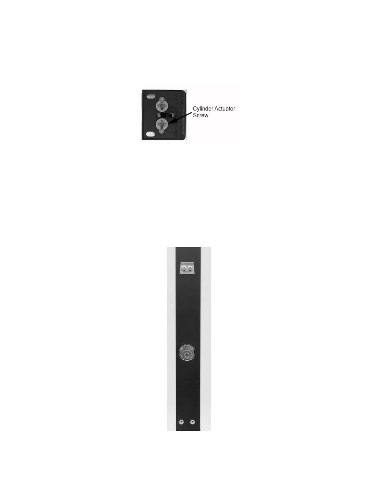
Replacing the Mortise Cylinder...........................................................33
TROUBLESHOOTING............................................................................37
Green light comes on, but lever will not retract latch-bolt...............37
No lights come on when pushbuttons are depressed.....................37
No tones sound when pushbuttons are depressed.........................37
Factory default codes not working. .................................................37
User codes not working...................................................................37
Operator stays unlocked.................................................................37
WARRANTY............................................................................................38
eFORCE 150 USER LOG.......................................................................39

5 80-0180-307, Rev A
INSTALLATION
Important Notes
The 3090-01 is designed exclusively for latching hardware including:
• Adams Rite 4500/4900 deadlatches
• Adams Rite 8000 series exit devices
• Yale 7200 series narrow stile exit devices
• Corbin Russwin ED4000 series
The 3090-02 is compatible with Adams Rite MS®Series Deadbolts only!
These units are not interchangeable. These instructions, and the
fasteners supplied, apply to metal door applications. Other door types
will need fasteners designed for the given medium.
IMPORTANT: This product must be installed according to all
applicable building and life safety codes!
Tools and Equipment Needed
The following common hand tools are needed for installation:
• Center punch
• Drill gun
• 1/4” [6.35 mm] drill bit
• Phillips screwdriver
• Pliers
• Flat tip screwdriver
• Pencil
The following additional equipment is needed:
NOTE: 1-1/2” cylinders require a 1/8” trim ring.
• Mortise Cylinder - 1” to 1-1/2” in length range with MS cam

6 80-0180-307, Rev A
Supplied Parts
NOTE 1: Figure 1 illustrates the supplied parts.
NOTE 2: A cam plug is supplied for either the 3090-01 or 3090-02.
Item Description Quantity
1 Mounting Bracket (Part Number 22-9076) 1
2 #10-32 x 5/8” Phillips Pan Head Screws with lock washer 4
3 Spindle (Part Number 22-9154) 1
4 5/64” Allen Key 1
5 Cylinder Locking Ring (Part Number 24-0061) 1
6 Locking Ring Spanner Tool (Part Number 22-0594) 1
Figure 1
Preparing the Door
NOTE: Template 80-0180-396-01 is used for Yale, Corbin Russwin
and SARGENT exit devices (see Figure 2).
1. SELECT the stick-on template to match the application.
2. MARK the backset and horizontal centerlines.
3. APPLY clear template over the centerline marks (see Figure 2).
4. CENTER-PUNCH the four (4) referenced mounting holes, and
REMOVE template.
5. DRILL holes at center-punch locations using a 1/4” [6.35 mm] drill
bit.
6. INSTALL Rivnuts according to instructions supplied in Rivnut kit.

7 80-0180-307, Rev A
7. INSTALL the mounting bracket with two (2) #10-32 x 5/8” pan head
screws (see Figure 3, “Installing the Mounting Bracket”).
Figure 2
Figure 3

8 80-0180-307, Rev A
Preparing the Spindle
NOTE 1: Steps 1–2 are performed for Adams Rite MS1850 Deadbolts,
4500/4900 Deadlatches, and 8000 Series Mortise Exit
Devices.
NOTE 2: One notch is added for a 2” thick door.
1. SNAP OFF the spindle at the fifth (5th) notch (see Figure 4).
2. INSERT the flat end into the exit device.
Figure 4
NOTE 1: Steps 3–4 are performed for Adams Rite 8600 Concealed
Vertical Rod Exit Devices.
NOTE 2: Two (2) notches are added for a 2” thick door.
3. SNAP OFF the spindle at the sixth (6th) notch (see Figure 5).
4. INSERT the flat end into the exit device.
Figure 5
NOTE 1: Steps 5–6 are performed for Adams Rite 8000 Series Surface
Vertical Rod and Rim Exit Devices, Yale 7200 Series Narrow
Stile Exit Devices, and Corbin Russwin ED4000 Series Exit
Devices.
NOTE 2: Two (2) notches are added for a 2” thick door.
5. SNAP OFF the spindle at the fourteenth (14th) notch (see Figure 6).
6. INSERT the “T” end into the exit device.
Figure 6

9 80-0180-307, Rev A
Configuring the Model 3090 for Lock Series
NOTE: Steps 1–3 are performed to configure a Model 3090-01 for a
mortise latch application using 4500/4900 Deadlatches
(including 8300/8400 Exit Devices).
1. CONFIGURE the supplied cam plug to match the hand of door (see
Figures 7 and 8).
2. INSERT cam plug into latch case with notch on the cam plug aligned
with latch case set screw.
3. TIGHTEN set screw and SECURE with the two brass cam plug
screws (see Figure 9).
Figure 7 Figure 8 Figure 9
NOTE: Steps 4–5 are performed to configure a Model 3090-01 for a
CVR exit device application using 8500/8600 Exit Devices.
4. INSTALL tailpiece adapter on the vertical rod.
5. FASTEN with Phillips screw (see Figure 10)
Figure 10

10 80-0180-307, Rev A
NOTE: Step 6 is performed to configure a Model 3090-01 for a RIM
exit device using 8700/8800 Exit Devices.
6. On the back side of the exit device, REMOVE only the lower Phillips
head screw, depending on hand of door, to free up the cylinder
actuator for use (see Figure 11).
Figure 11
NOTE: Steps 7–8 are performed to configure a Model 3090-02 for a
MS 1850 application using a MS®series Deadbolt.
7. For MS Deadbolt, INSERT cam plug into lock case ensuring the
notch on the cam plug is aligned with lock case set screw.
NOTE: Cam Plug must be positioned below door surface.
8. TIGHTEN set screw and SECURE with the two (2) brass cam plug
screws (see Figure 12).
Figure 12

11 80-0180-307, Rev A
Handing the eForce 150
NOTE: The eForce 150 is shipped in a non-handed, neutral position
with the access cover off (see Figure 12).
1. IF installing the Model 3090-02,
THEN GOTO the “Installing the Mortise Cylinder” section.
2. To hand the eForce 150, ROTATE the handle until it clicks into the
horizontal position (see Figure 13).
Figure 13
NOTE: The output hub, located on the back of the eForce 150, is
shipped with a clockwise rotation as viewed from rear. In
some instances, this rotation must be changed to match the
device and/or hand of the door (see Table 1, “Handing Setup).
Table 1. Handing Setup
Device Type Left Hand
Reverse Rotation Right Hand
Reverse Rotation
SVR Clockwise Clockwise
Mortise Latch Counter-Clockwise Clockwise
CVR Clockwise Clockwise
RIM Counter-Clockwise Counter-Clockwise

12 80-0180-307, Rev A
NOTE 1: Hubs that have (+) shape are for use with deadlatches and
exits only.
NOTE 2: Hubs that have (-) shape are for use with deadbolts only.
3. To change rotation and reconfigure the unit to the opposite rotation,
INSERT a flat screwdriver into the output hub (see Figure 14)
located on the back of the eForce 150, and TURN approximately
270° clockwise or counter-clockwise.
Figure 14
Installing the Mortise Cylinder
CAUTION
There are wires connecting the housing and back plate assembly.
These must be handled with care to not cause damage. Over-
tightening must also be avoided.
1. Using a Philips head screwdriver, REMOVE the eight (8) #10-32 x
5/8” screws on the back of the eForce 150 (see Figure 15), and
gently LIFT the back plate off the housing.
Figure 15

13 80-0180-307, Rev A
2. INSTALL the cylinder into housing.
3. SECURE and FASTEN with supplied locking ring using locking ring
spanner tool (see Figure 16).
Figure 16
CAUTION
There are wires connecting the housing and back plate assembly.
These must be handled with care to not cause damage. Over-
tightening must be avoided. Additionally, a dummy cylinder cannot
be used.
4. Gently PLACE back plate back on housing and SECURE with
eight (8) #10-32 x 5/8” screws.
NOTE: Step 5 is an optional step to install a RSK-3090 Remote
Switch Kt.
5. For applications that require a remote activation switch, PLUG the
RSK-3090 into the board (see Figure 17).

14 80-0180-307, Rev A
Figure 17
Mounting the eForce 150
1. INSERT the properly dimensioned spindle into the output hub.
NOTE: The eForce 150 must sit flush on the door surface.
2. MOUNT the eForce 150 onto mounting bracket and GUIDE the
spindle into the cam plug (see Figures 18 and 19 [MS 1850
configuration shown]).
Figure 18 Figure 19
Spindle

15 80-0180-307, Rev A
3. SECURE with two (2) #10-32 x 5/8” screws (see Figure 20).
Figure 20
Installing the eForce 150 Batteries
NOTE: Lithium batteries are suggested in climates reaching 20°F and
below.
1. Properly INSERT four (4) Size AA Alkaline batteries into battery
holder ensuring proper polarity.
2. PLUG the battery pack into the eForce 150 connector (see
Figure 21).
3. INSERT the battery case into the eForce 150 (see Figure 22).
NOTE: A battery moisture shield is pre-installed at the factory to
protect the batteries from the elements.
4. SLIDE battery cover over the inserted battery case.
5. INSERT the included 5/64” Allen key and TURN clockwise two full
turns to secure the battery cover (see Figure 23).
Figure 21 Figure 22

16 80-0180-307, Rev A
Figure 23
SETTING UP AND USING THE eFORCE 150
General Information
The eForce 150 has the following features and requirements:
• A keypad (with numbers 0-9, *, and #) that is used for
programming. In normal operating mode, the * key is used as
the ENTER key after user code entry.
• Each key press flashes the yellow LED and sounds one tone.
Audible and visual keypad feedback can be disabled (see
programming instructions).
• Master and Emergency Codes must be reprogrammed from the
factory pre-set codes before user codes may be entered. The
factory preset Master and Emergency codes (1234 & 4321)
cannot be revised back into the unit.
• All codes need to be entered twice for validation during
programming. If the two entered codes do not match, the eForce
150 will exit programming mode and the previous code will
remain active.
• Following a number of 5 successive invalid code entries, the red
LED flashes once and a tone indicates that the eForce 150 will
no longer accept further entries for 15 seconds. One tone per
second sounds during this time. Refer to programming
instruction to change default settings for successive invalid code
entries and error lockout time.

17 80-0180-307, Rev A
Programming Information
1. PERFORM the following to enter the programming mode.
a. PRESS and HOLD the # key until the yellow LED flashes three
times.
b. RELEASE the # key and the yellow LED will begin to flash
continually.
NOTE: At the end of each programming step ending with the #
key (ENTER), the green LED will flash twice and the
sounder will emit 2 tones to indicate that valid values were
accepted.
c. PROGRAM, as required.
d. WHEN the end of the programming sequence is reached,
THEN WAIT two (2) seconds for the device to time out and
return to normal operating mode,
OR PRESS the * key to exit programming mode.
Speed Mode
1. PERFORM the following to enter the speed mode.
NOTE: The following step initiates the “speed programming
mode,” eliminating the need to re-enter the Master or
Supervisor code.
a. At the end of a programming sequence, PRESS the # key within
2–4 seconds to program additional codes.
NOTE: For the following steps, the red LED will flash and a tone
will indicate that the programming mode has been exited.
b. In programming mode, PRESS the * key at any time to exit this
mode.
c. WAIT 2 seconds before entering any code.
NOTE 1: The programming mode will exit automatically if an invalid
code is entered during programming (indicated by a red
LED flash and a tone).
NOTE 2: The eForce 150 will always return to the standard user
mode after the programming mode is exited.
d. IF the programming mode has exited,
THEN PRESS the # key to reinitiate the programming mode.

18 80-0180-307, Rev A
User Code Descriptions
NOTE: In user mode, entries must be followed by the * key.
The following are the user code descriptions:
• Master Code. The default Master code setting (1234) must be
changed before programming additional user codes. In addition
to using this code to program Emergency and Supervisor codes,
the Master code can be used to unlock the device. The code
must be between 4 and 7 digits.
• Emergency Code. The default Emergency code setting (4321)
must also be changed prior to programming the eForce 150
features and codes, though it is not used in programming the
eForce 150. This code unlocks the device in all conditions,
including a low battery condition or “blackout.” It will open the
eForce 150 for the preset time (10-second default). The code
must be between 4 and 7 digits.
• Supervisor Code. The Supervisor code has no preset default,
so it must be programmed by the user if needed. It is used to
unlock the eForce 150, even under low battery conditions. It
allows for programming every code except the Master code, and
is also required to delete codes. Normal and One Time user
codes (6-152) may be entirely deleted or partially deleted in a
block. The Emergency, Lockout, and Passage codes may be
singly deleted, rendering these functions completely non-
operational (they will not return to default once deleted). The
Supervisor code must be between 4 and 7 digits.
• Lockout Code. The Lockout code is used to restrict Normal
User codes (6-152) from gaining access. Entry of Lockout Mode
is indicated by a green LED flash and two tones, with a pause
followed by two additional tones. Only the Master, Emergency,
and Supervisor codes can override the Lockout code. Entering
the Lockout code a second time will cancel the Lockout and
allow access with Normal User codes. Exit of Lockout Mode is
indicated by a green LED flash and two tones. The Lockout
code must be between 4 and 7 digits.
• Passage Code. The Passage code is used to enable or disable
the Passage mode. Entering the Passage code will cause the
device to allow free ingress entry (Passage enabled is indicated
by green LED flash and 3 tones). A second entry of the Passage
code will return the eForce 150 to the Normal User Mode (exiting
Passage Mode is indicated by green LED flash and 2 tones).
The Passage Mode operates when the battery is low and can be
overridden by the Lockout code. The code must be between 4
and 7 digits.

19 80-0180-307, Rev A
• Normal User Codes. Normal User codes are used to briefly
unlock the device. A correct code entry is indicated by a green
LED flashing once per second. An incorrect code entry is
indicated by red LED flash and 3 tones. Up to 144 different
Normal User codes may be programmed. These codes may not
be programmed until after the default Master and Emergency
codes have been reprogrammed. They must be between 2 and
7 digits.
• One-Time User Codes. One-Time user codes are used to
unlock the device and are only valid for a single operation of the
eForce 150. A correct code entry is indicated by a green LED
flashing once per second. An incorrect code entry is indicated
by red LED flash and 3 tones. Different One-Time user codes
may be programmed into locations 151 and 152. These codes
may not be programmed until after the default Master and
Emergency codes have been reprogrammed. They must be
between 2 and 7 digits. After a One-Time user code is used to
operate the eForce 150, the same or a new code must be
programmed into the eForce 150 using the Master or Supervisor
codes.
Features and Options Descriptions
NOTE: Program Command Codes (PCC) are designated codes for
programming and are always entered after the Master or
Supervisor code during programming mode.
The following are the eForce 150 features and options:
• Error Lockout. The eForce 150 will stop accepting key presses
after 3 successive invalid entries. Error Lockout is indicated by
one red LED flash and 3 tones, followed by one tone per second
for the duration of the Lockout time. The eForce 150 will not
accept any key presses during this preset (PCC 34) time. The
Error Lockout function overrides the horn disable
function (PCC 31).
• Low Battery Indicator. When the battery voltage drops below
4.0 volts, the eForce 150 will emit 4 tones before allowing entry.
If the battery voltage drops below 3.8 volts, the eForce 150 will
enter blackout mode, indicated by 4 tones followed by 4 tones,
and will not open. The eForce 150 will function for the Master,
Emergency, and Supervisor codes only.
• Piezo Sounder. This will emit a tone with each keystroke and
varying tones to indicate various conditions. The sounder can be
disabled using the Master or Supervisor code (PCC31).

20 80-0180-307, Rev A
• LED Indicator. All 3 LED’s can be disabled in User Mode by the
Master or Supervisor code (PCC32), but will remain enabled in
programming mode. Yellow indicates programming mode.
Green indicates successful entry. Red indicates input error. The
LED’s will also flash to indicate various conditions.
• Variable Re-lock time. The duration that the eForce 150
remains unlocked can be adjusted (PCC 44) from 1 to 9
seconds. Default is 4 seconds.
Programming the User Codes
The eForce 150 can support 152 individual user codes. Each code is
assigned a code location (1–152) in addition to a user name and the
code’s programmed digits. Program Command Code 51 is used for
programming Master, Emergency, Supervisor, Lockout, Passage,
Normal, and One Time User codes. The Master code is always code
location number 1 and can be used to operate and program the eForce
150. A record log in included in this document to assign and log all
codes before proceeding on to programming. The log should be stored
in a secure location.
Master Code
1. PERFORM the following to program the Master Code (Location 1).
NOTE: Yellow LED will blink continuously during programming.
a. PRESS and HOLD # for approximately 5 seconds, and
RELEASE when the yellow LED blinks.
NOTE: After Step b, there will be green LED flash and 2 short
tones.
b. ENTER 1234#.
NOTE: After Step c, there will be green LED flash and 2 short
tones.
c. ENTER 51#
NOTE: After Step d, there will be green LED flash and 2 short
tones.
d. ENTER 1#
This manual suits for next models
1
Table of contents
Other ADAMS RITE Lock manuals