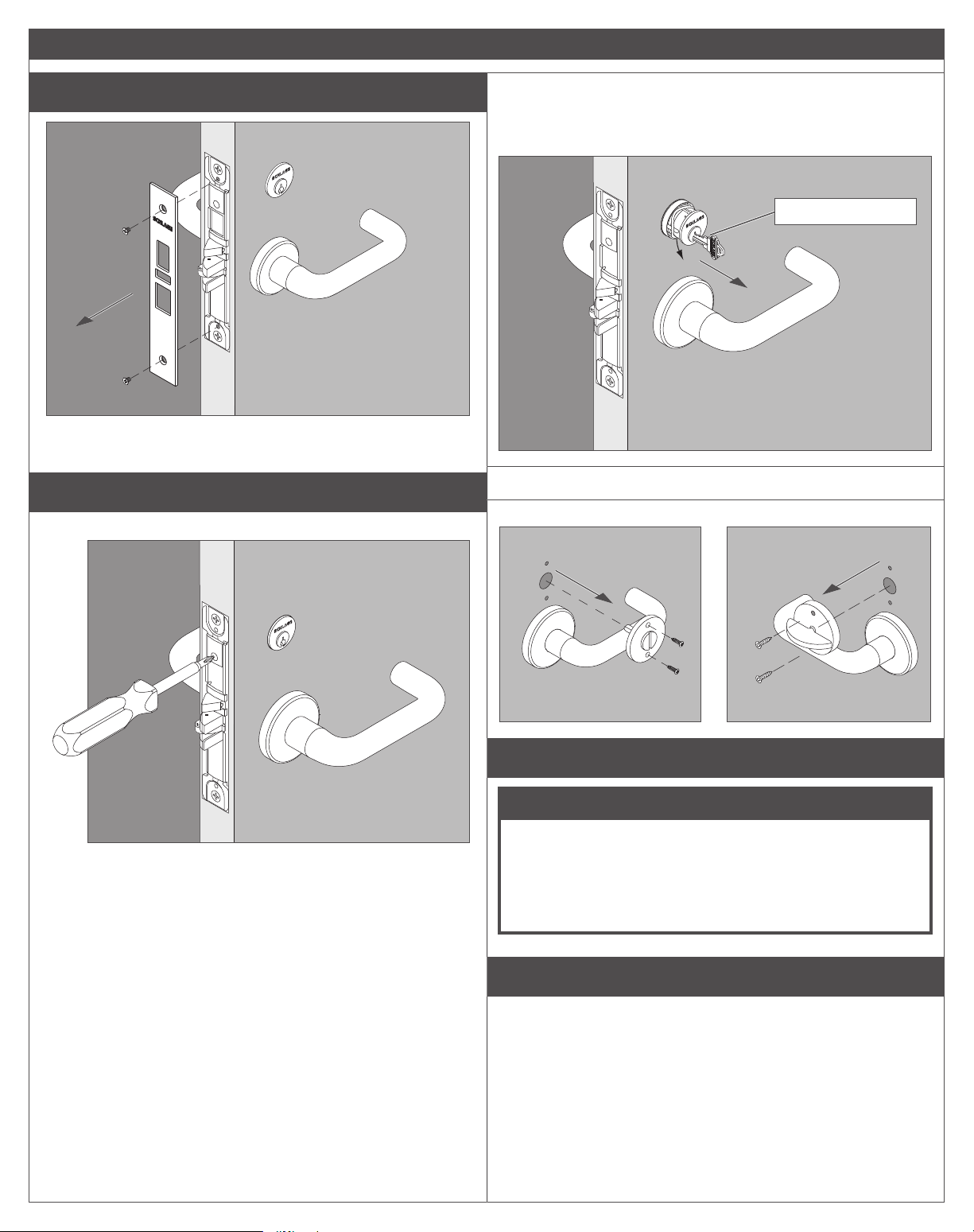
El borde con indicador está
disponible para el interior o el
exterior de la puerta para las
funciones permitidas. El borde
sin indicador se coloca en el
lado opuesto de la puerta.
Para una adaptación, vea la
página 23.
La garniture d’indicateur est
vendue pour l’Intérieur ou
l’extérieur de la porte pour
les fonctions autorisées. Une
garniture sans indicateur est
fournie pour le côté opposé
de la porte.
Pour la rénovation,
reportez-vous à la page 23.
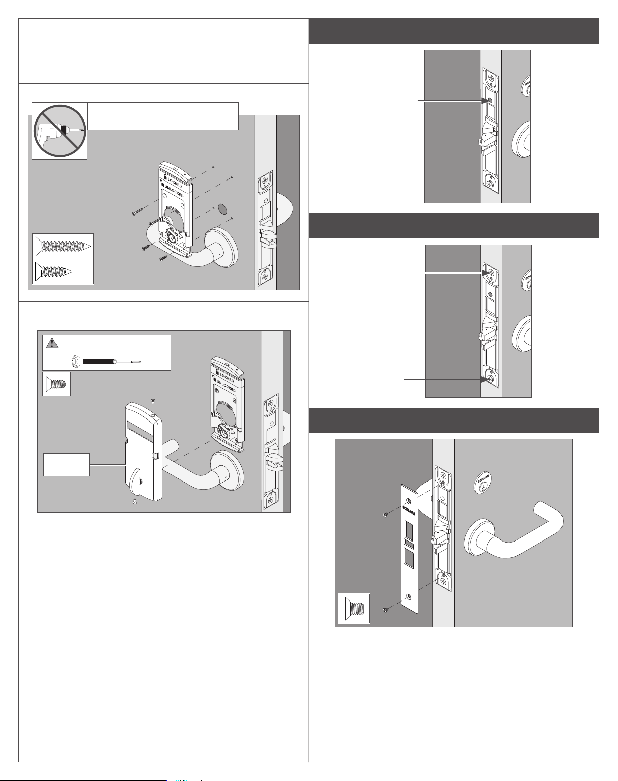
La cerradura L9000 con
indicador no está destinada
para aplicaciones en puertas
exteriores.
Conrme la ubicación
deseada (interior o exterior)
antes de la instalación.
La serrure L9000 avec
indicateur n’est pas conçue
pour des utilisations sur une
porte extérieur.
Conrmez l’emplacement
souhaité (intérieur ou
extérieur) avant l’installation.
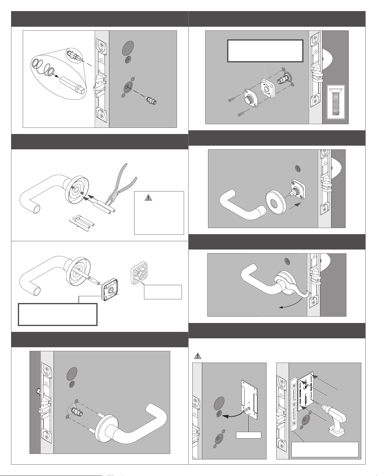
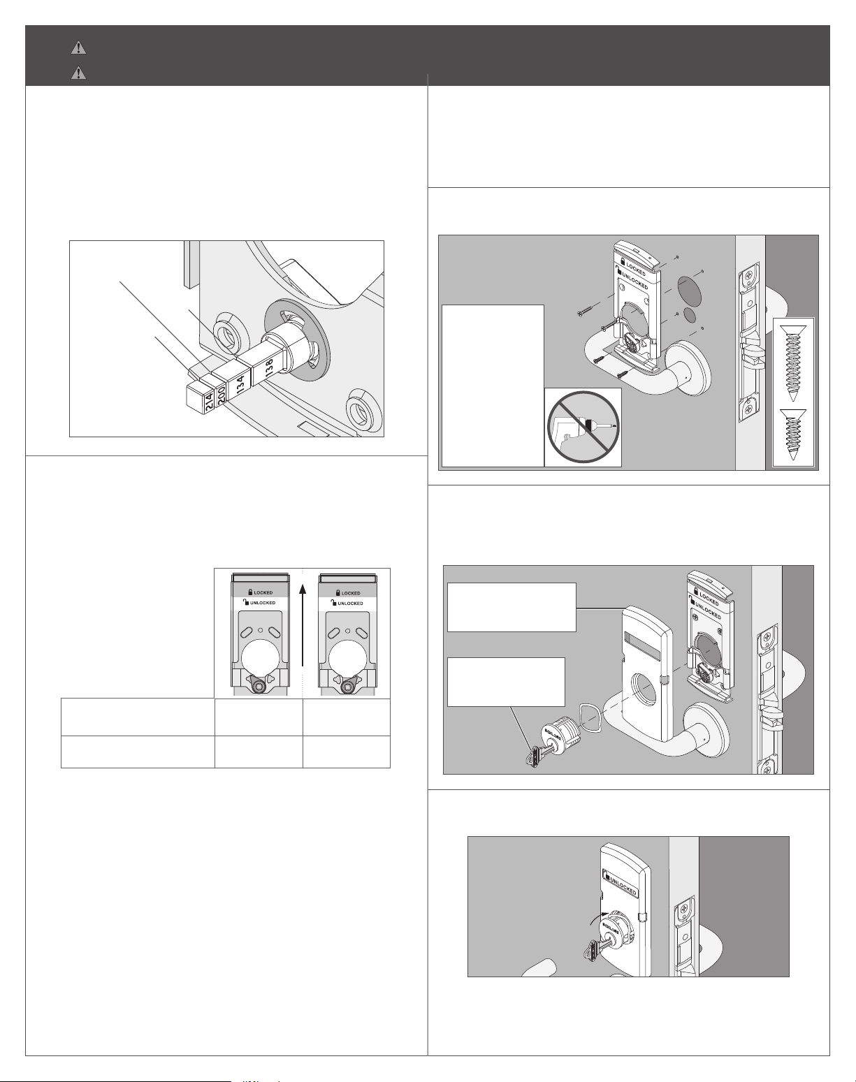
Compruebe las dimensiones
de preparación de la puerta con la
plantilla incluida en el paquete.
Vériez les dimensions de
préparation de la porte à l’aide du
gabarit inclus dans l’emballage.
O
OU
O
OU
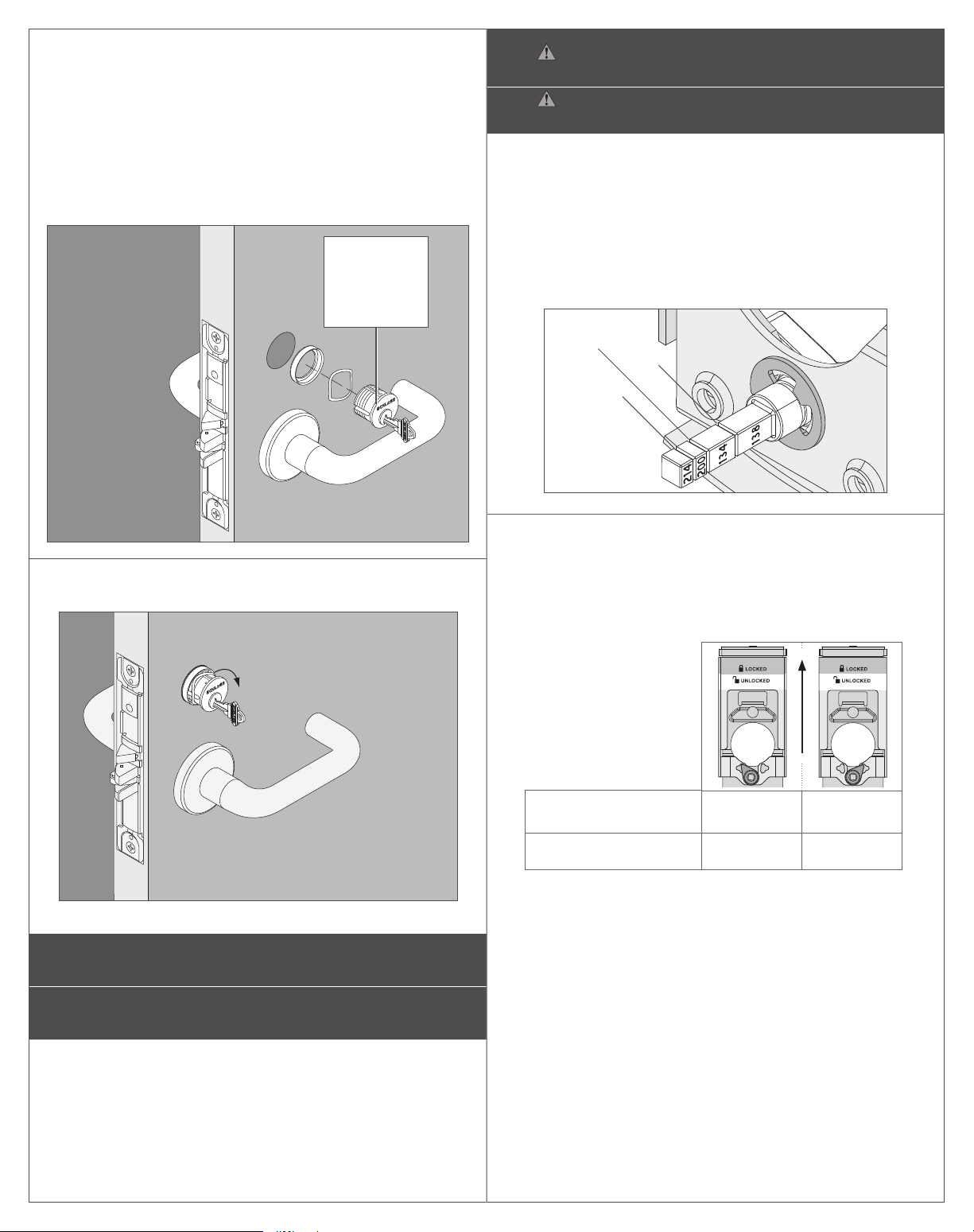
Se muestra el indicador del cilindro interior x el cilindro sin indicador en el exterior.
Indicateur de cylindre intérieur x cylindre sans indicateur illustrés.
Cilindro
Cylindre
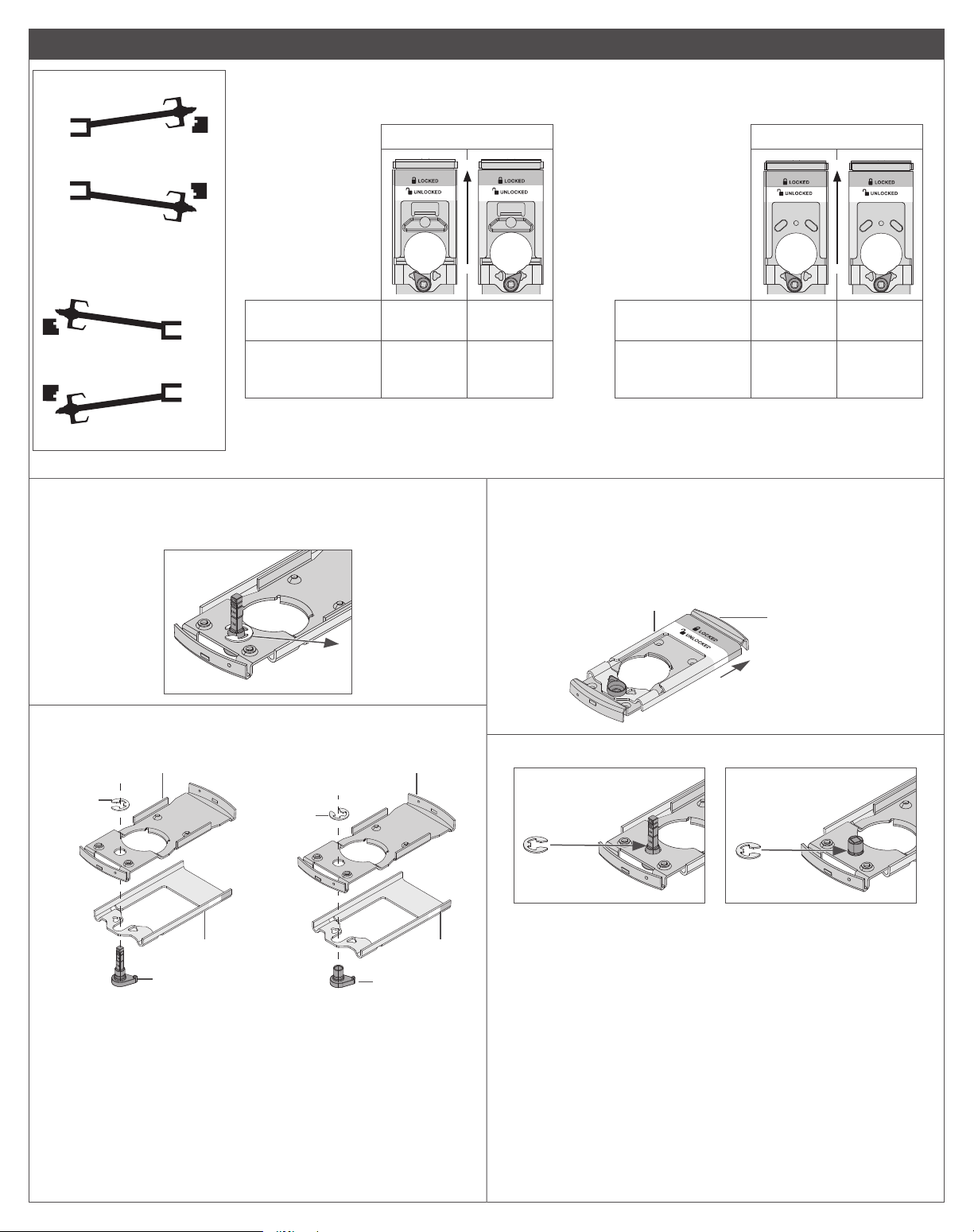
Opciones
indicador:
Options
d’indicateur:
Giro con
moneda
Barrette à
fente
Giro
manual
Barrette
tournante
Privacidad
Intimité
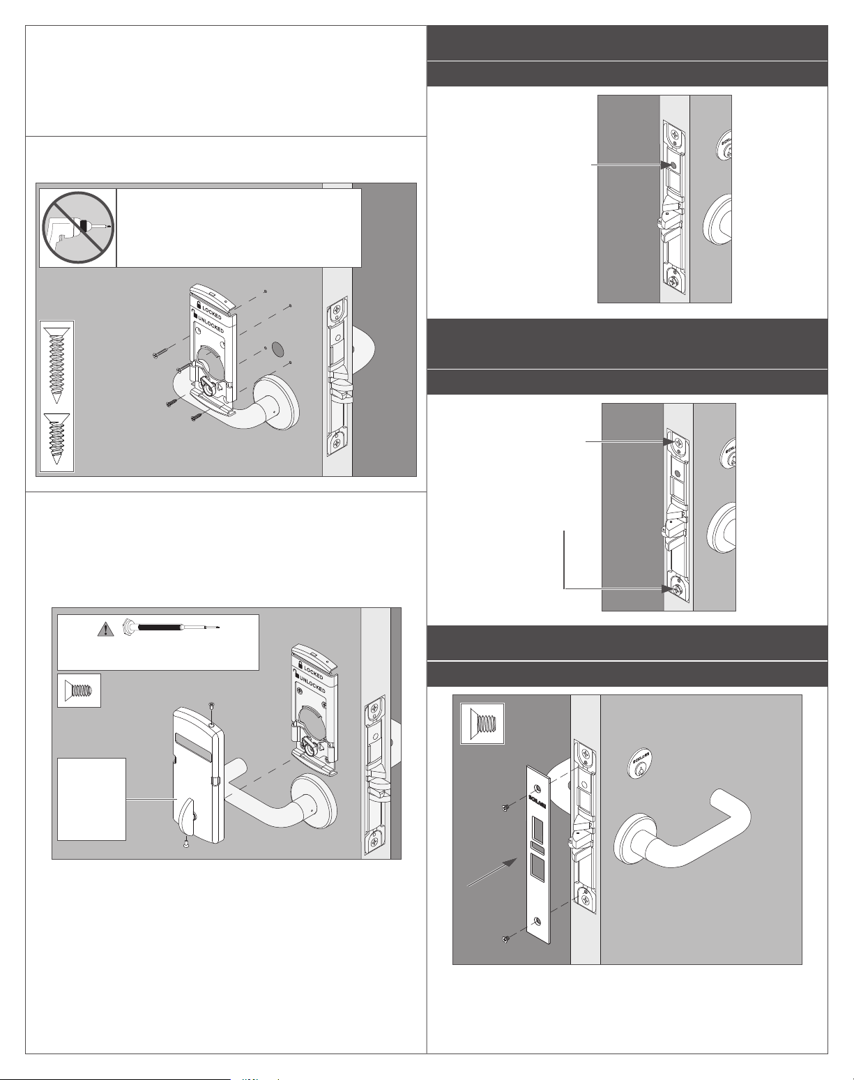
Herramientas para la instalación:
Outils requis pour l’installation :
Incluido/Inclus No incluidas/Non inclus
Opciones sin
indicador:
Options sans
d’indicateur: Giro con
moneda
Barrette à
fente
Giro
manual
Barrette
tournante
Cilindro
Cylindre
Privacidad
Intimité
Cerradura Serie L9000 con seccional de seguridad con indicador
Serrure de la série L9000 avec sectionnel d’indicateur d’entrée de serrure
Cerradura L9000 con indicador
Serrure L9000 avec indicateur
Instrucciones de instalación
Notice d’installation
P516-909