Adaptrum ACRS 2.0 User manual

Rev 2016.05.16
Adaptrum ACRS2.0 Quick Start Guide (International)
Cognitive Radio Systems
ACRS2.0 Quick Start Guide
International Manual

2016
Adaptrum ACRS2.0 Quick Start Guide (International)
FCC Regulatory Information
This device complies with part 15 of the FCC Rules. Operation is subject to the following two conditions: (1) This device may not
cause harmful interference, and (2) this device must accept any interference received, including interference that may cause
undesired operation. Any changes or modifications not expressly approved by the party responsible for compliance could void
the user’s authority to operate the equipment.
Part 15 TV Band Device Notice
This equipment has been tested and found to comply with the rules for TV bands devices, pursuant to part 15 of the FCC rules.
These rules are designed to provide reasonable protection against harmful interference. This equipment generates, uses and can
radiate radio frequency energy and, if not installed and used in accordance with the instructions, may cause harmful interference
to radio communications. If this equipment does cause harmful interference to radio or television reception, which can be
determined by turning the equipment off and on, the user is encouraged to try to correct the interference by one or more of the
following measures:
(1) Reorient or relocate the receiving antenna.
(2) Increase the separation between the equipment and receiver.
(3) Connect the equipment into an outlet on a circuit different from that to which the receiver is connected.
(4) Consult the manufacturer, dealer or an experienced radio/TV technician for help.
Caution: Exposure to Radio Frequency Radiation
To comply with FCC RF exposure compliance requirements, for fixed configurations, a separation distance of at least 40 cm
must be maintained between the antenna of this device and all persons.
This device must not be co-located or operated in conjunction with any other antenna or transmitter in contravention to
specifications herein.

2016
Adaptrum ACRS2.0 Quick Start Guide (International)
Contents
INTRODUCTION............................................................................................................................................. 7
Document Goal ......................................................................................................................................... 7
Required Items.......................................................................................................................................... 7
Basic Steps ................................................................................................................................................ 7
Important Notes........................................................................................................................................ 8
INVENTORY ................................................................................................................................................... 9
BASE ............................................................................................................................................................ 10
Setup ....................................................................................................................................................... 10
Channel Selection ...................................................................................................................................13
Start Service ............................................................................................................................................15
CLIENT ......................................................................................................................................................... 16
Setup ....................................................................................................................................................... 16
Channel Selection ...................................................................................................................................17
MAC Address Specification ..................................................................................................................... 19
Link Status Check .................................................................................................................................... 20
INSTALLATION............................................................................................................................................. 21
Radio Mounting ...................................................................................................................................... 21
Hardware ............................................................................................................................................21
Radio Unit ...........................................................................................................................................21
Ethernet cable..................................................................................................................................... 22
Antenna Orientation............................................................................................................................... 25
Basic .................................................................................................................................................... 25
Indoor Testing .....................................................................................................................................25
Multiple CLIENTs .................................................................................................................................25
Collocation ..........................................................................................................................................26
Relay.................................................................................................................................................... 26
Antenna Mounting.................................................................................................................................. 27
Hardware ............................................................................................................................................27
Vertical Pole ........................................................................................................................................28
Horizontal Pole.................................................................................................................................... 29
Antenna Cable..................................................................................................................................... 30

2016
Adaptrum ACRS2.0 Quick Start Guide (International)
APPENDIX.................................................................................................................................................... 31
Sync Laptop Time to Internet.................................................................................................................. 31
Disabling WiFi.......................................................................................................................................... 33
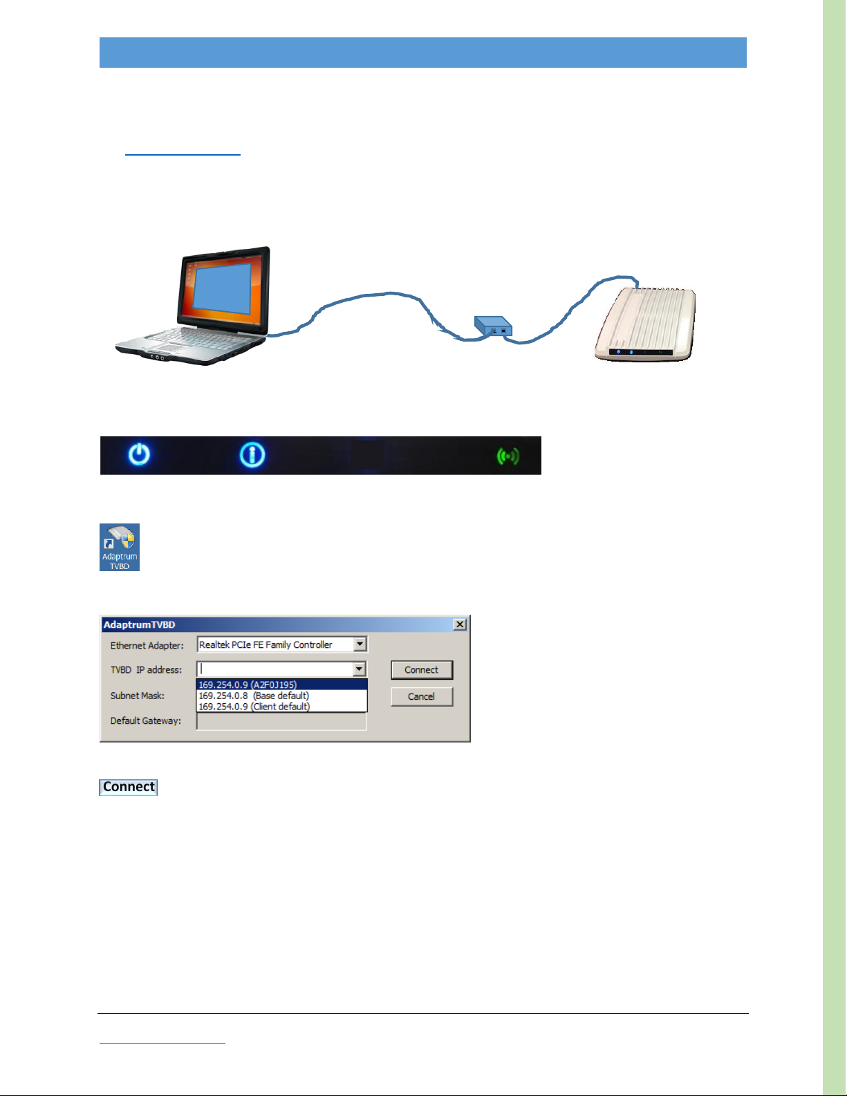
Installing Software ..................................................................................................................................34
AdaptrumTVBD GUI ................................................................................................................................38
Format................................................................................................................................................. 38
Functions.............................................................................................................................................39
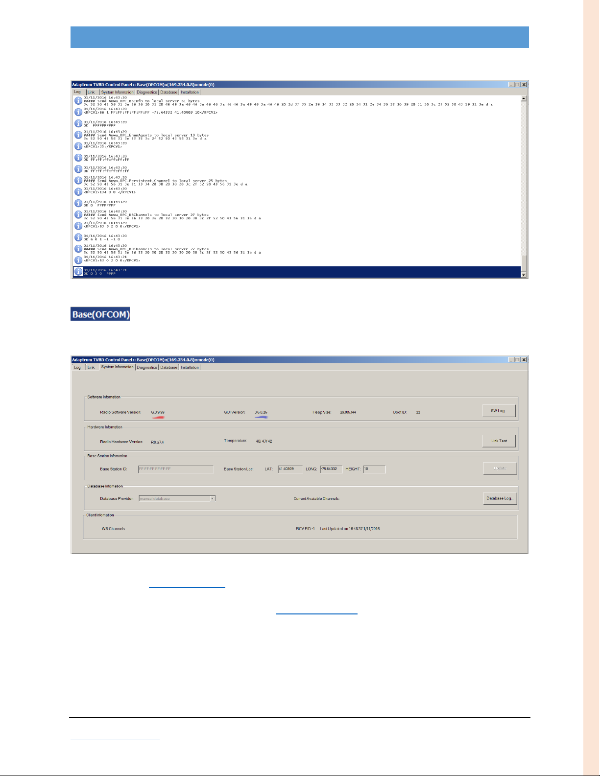
Log Tab ................................................................................................................................................ 40
Link Tab ............................................................................................................................................... 41
System Information Tab...................................................................................................................... 43
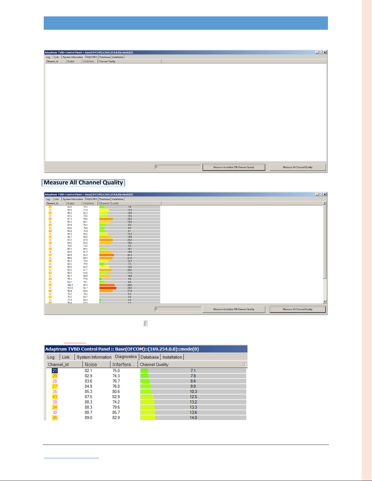
Diagnostics Tab ...................................................................................................................................44
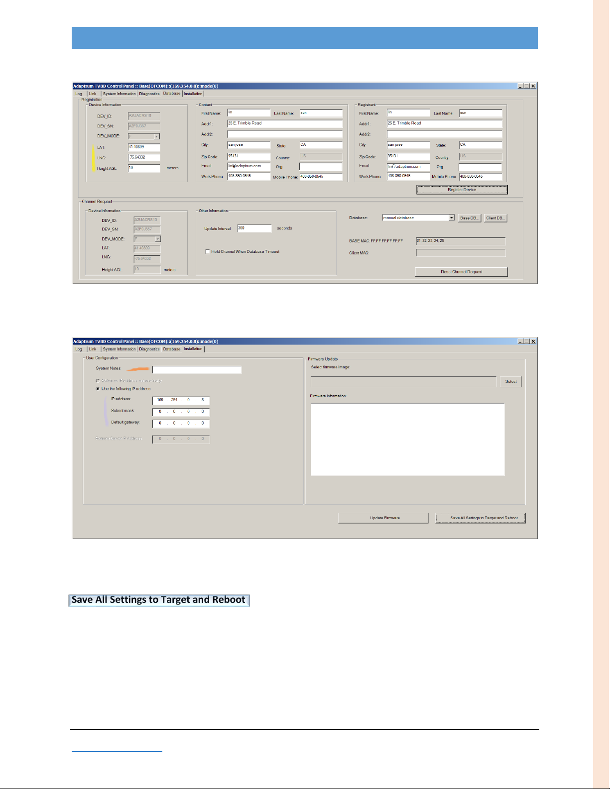
Database Tab ......................................................................................................................................46
Installation Tab....................................................................................................................................48
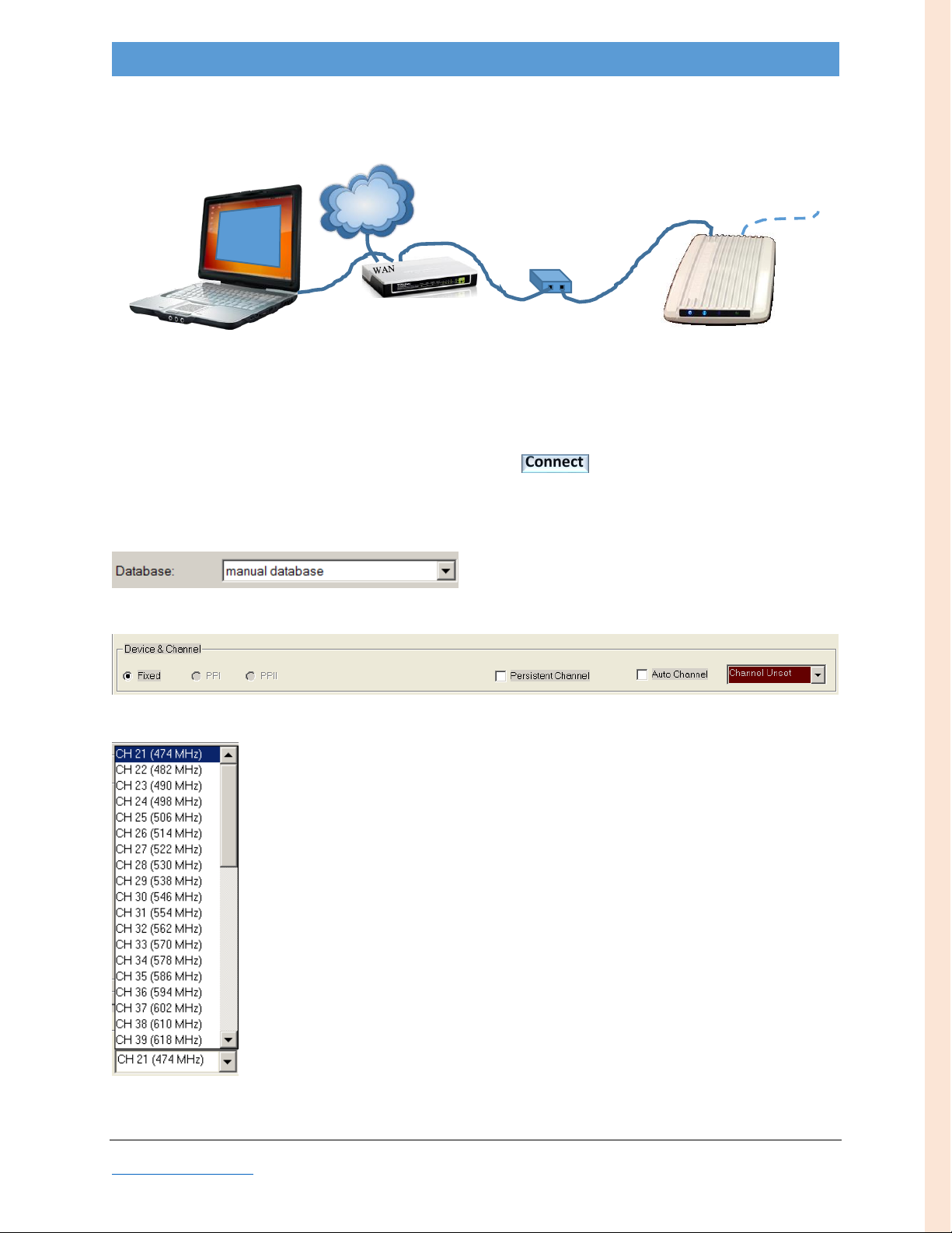
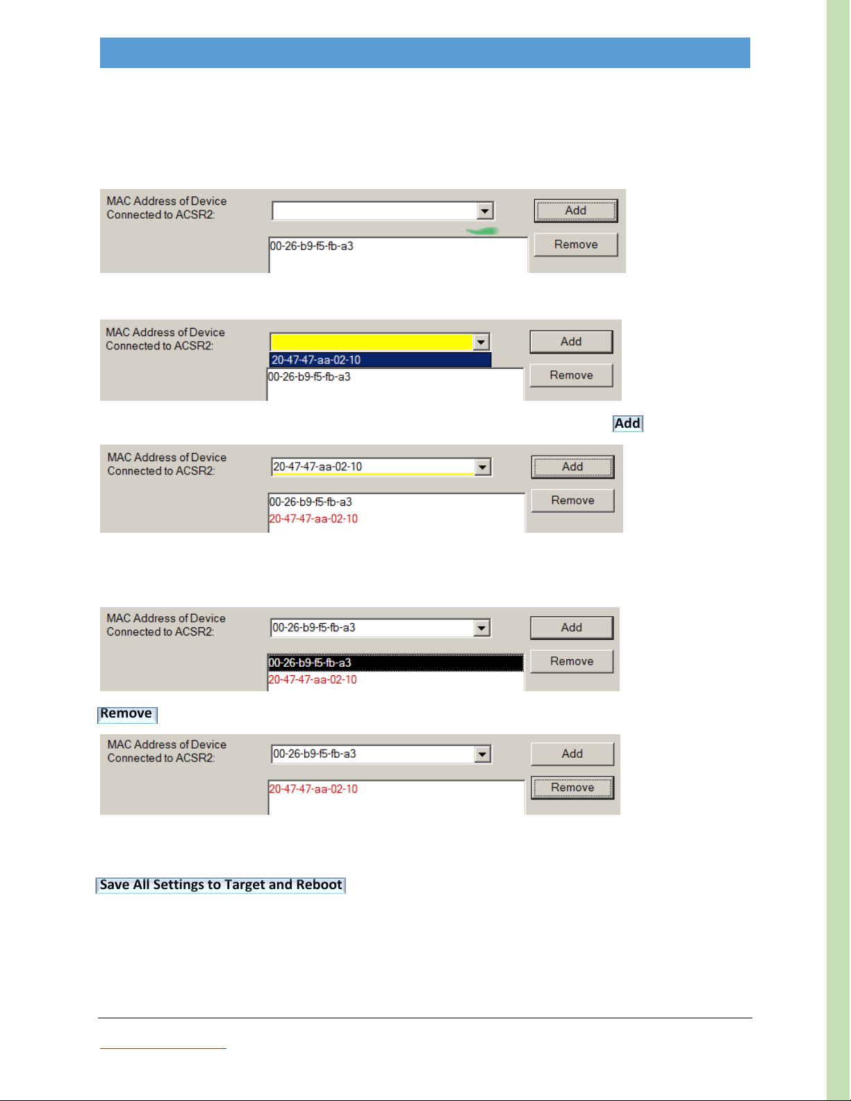
Device & Channel pane....................................................................................................................... 50
Updating Firmware (Local)......................................................................................................................51
Remote Update....................................................................................................................................... 52
Firmware .............................................................................................................................................52
Configuration ......................................................................................................................................53
Log File, reading ......................................................................................................................................54
Remote................................................................................................................................................ 54
Local .................................................................................................................................................... 54
Checking Link Status ............................................................................................................................... 55
LED Interpretation .................................................................................................................................. 56
Spectrum Scan Channel Quality.............................................................................................................. 56
8MHz Channels .......................................................................................................................................57
Modulation Rates.................................................................................................................................... 58
Mechanical Dimensions .......................................................................................................................... 59
Markings .................................................................................................................................................60
Systems Specifications ............................................................................................................................ 61
GUI crash................................................................................................................................................. 62
INDEX .......................................................................................................................................................... 63
CONTACT INFO............................................................................................................................................64

2016
Adaptrum ACRS2.0 Quick Start Guide (International)
Figures
Figure 1: ACRS Mounting Diagram.............................................................................................................. 21
Figure 2: ACRS bottom (Ethernet RJ45 plug on the right) ..........................................................................22
Figure 3: Ethernet weather-resistant boot ................................................................................................. 22
Figure 4: Ethernet weather-resistant boot (two pieces) ............................................................................ 22
Figure 5: Ethernet cable with weather-resistant boot assembly................................................................23
Figure 6: Ethernet cable with weather-resistant boot assembled ............................................................. 23
Figure 7: Ethernet cable weather seal ........................................................................................................23
Figure 8: Ethernet connector in place......................................................................................................... 24
Figure 9: Ethernet cable with weather-resistant boot secured in ACRS enclosure....................................24
Figure 10: Basic Antenna Orientation & Direction ..................................................................................... 25
Figure 11: Multi-client Antenna Orientation .............................................................................................. 25
Figure 12: Antenna Collocation Separation Distances................................................................................26
Figure 13: Fracarro Antenna Mounting Hardware .....................................................................................27
Figure 14: Fracarro Antenna Mount on Vertical Pole, bolt head positioning............................................. 28
Figure 15: Fracarro Antenna Mount on Vertical Pole................................................................................. 28
Figure 16: Fracarro Antenna Mount on Horizontal Pole ............................................................................29
Figure 17: Fracarro Antenna Cable SMA Connector Through Weather Sleeve..........................................30
Figure 18: Fracarro Antenna F-type connector........................................................................................... 30
Figure 19: Antenna Cable Secured to Antenna and ACRS .......................................................................... 30
Figure 20: Default GUI screenshot, Link tab and Device & Channel pane.................................................. 38
Figure 21: GUI screenshot: Log tab............................................................................................................. 40
Figure 22: GUI screenshot: Link Chart View................................................................................................ 41
Figure 23: GUI screenshot: Link List View................................................................................................... 42
Figure 24: GUI screenshot: BASE System Information tab ......................................................................... 43
Figure 25: GUI screenshot: CLIENT System Information tab ......................................................................44
Figure 26: GUI screenshot: Diagnostics tab................................................................................................ 45
Figure 27: GUI screenshot: BASE Database tab .......................................................................................... 46
Figure 28: GUI screenshot: CLIENT Database tab .......................................................................................47
Figure 29: GUI screenshot: BASE Installation tab .......................................................................................48
Figure 30: GUI screenshot: CLIENT Installation tab .................................................................................... 49
Figure 31: GUI screenshot: BASE Device & Channel pane..........................................................................50
Figure 32: GUI screenshot: CLIENT Device & Channel pane ....................................................................... 50

2016
Adaptrum ACRS2.0 Quick Start Guide (International)
Tables
Table 1: GUI Functions ................................................................................................................................ 39
Table 2: Log tab Description ....................................................................................................................... 40
Table 3: Link Chart View Description ..........................................................................................................41
Table 4: Link List View Description.............................................................................................................. 42
Table 5: Link List View Field Descriptions ................................................................................................... 42
Table 6: BASE System Information Field Descriptions................................................................................ 43
Table 7: CLIENT System Information Field Descriptions ............................................................................. 44
Table 8: Diagnostics Field Descriptions....................................................................................................... 45
Table 9: BASE Database Field Descriptions................................................................................................. 46
Table 10: CLIENT Database Field Descriptions............................................................................................47
Table 11: BASE Installation Field Descriptions............................................................................................ 48
Table 12: CLIENT Installation Field Descriptions......................................................................................... 49
Table 13: Device & Channel pane Field Descriptions.................................................................................. 50
Table 13: LED Interpretation table .............................................................................................................56
Table 14: 8MHz Channel Frequency List ................................................................................................... 57
Table 15: Modulation Rate Selection List ...................................................................................................58
Document
Conventions
In this guide, bold type font indicates proper names of software executables, GUI tabs, or GUI buttons.
Button text is embellished with this outline:
Revision
The date code found in the footer is the document revision number.

2016
Adaptrum ACRS2.0 Quick Start Guide (International)
INTRODUCTION
Document Goal
This document guides users in setting up and configuring their Adaptrum ACRS2.0 Cognitive Radio
System BASE and CLIENT (International configuration) units. The steps (and “required items”) described
below are intended for two purposes:
1. to set up and test a P2P (single BASE, single CLIENT) system in an office/lab environment
2. to install a P2P system in the field.
To perform the tasks described herein, you will need the following items:
Required Items
(2) laptops
(1) ACRS2.0 unit BASE (International configuration)
(1) ACRS2.0 unit CLIENT (International configuration)
(2) antennas (LP45F)
(2) PoEs
(1) switch & power adapter
(1) router & power adapter
(2) International power cords
(5) Ethernet cables (4 for PoEs, 1 to internet)
(2) antenna mounting hardware
(-) wrench and/or socket set (to fasten ACRS & antenna mounts)
(?) extension cords
Basic Steps
The basic setup steps are as follows:
1. Inventory receivables
2. Synchronize Laptop(s) with Internet Time
3. Install Software on Laptop(s)
4. Set up Base
a. Select Channel
i. Enter LAT/LNG/AGL
ii. Run spectrum scan
iii. Specify channel
b. Start Service
5. Set up Client
a. Provide LAT/LNG/AGL
b. Select Channel
c. Specify MAC Address(es)
6. Check Link Status

2016
Adaptrum ACRS2.0 Quick Start Guide (International)
Important Notes
ACRS Update Order
When updating units, it is imperative that CLIENTs are updated before BASE units.
Antenna Orientation
It is recommended to orient antenna ‘fins’ vertically. CLIENT antennas should point directly toward the
BASE, and the BASE should point into the center of the CLIENTs. (See Antenna Orientation Appendix.)
Auto Update
Do not leave Auto Update on. It is recommended to only turn this on while you are actively observing
the results. While on, this function is consuming computational bandwidth. When done, turn it back off.
Indoor Testing
When doing indoor short-range testing, the antennas connected to the radios should be pointed in
opposite directions to reduce the received power level and avoid overloading. See Figure 12.
Multiple Units
Make sure to change unit IP addresses when installing multiple units. All BASEs are delivered with
default address 169.254.0.8; all CLIENTs are delivered with default address 169.254.0.9.
Remote Updates
CLIENTs MUST BE updated before the BASE.
BASE must Start Service, and link with CLIENT must be established.
BASE Auto Update must be off, but Update Status must be performed at least once.
Ensure Remote Config Auto Channel box is checked so unit will reconnect after reboot.
Ensure CLIENT channel selection list contains the channel(s) the BASE will transmit on.
When remotely updating CLIENTs to a new channel, obviously the CLIENT will thereafter be
incommunicado until the BASE transmits on the new channel. Be sure to select a clean channel.
Software Updates
When updating software, to ensure proper communication, update both BASE and CLIENT control
laptops to the same version.
WiFi Disable
Be sure to disable (not just disconnect) wifi before operating the GUI. See Disabling WiFi Appendix.
After the GUI is opened, wifi may be re-enabled.

2016
Adaptrum ACRS2.0 Quick Start Guide (International)
INVENTORY
Before getting started, the first thing you should do is inventory the packages you receive. Each ACRS
box should contain the following items:
1. ACRS 2.0 unit (“BASE” or “CLIENT” per label on rear)
2. ACRS-to-antenna cable
3. Ethernet cable weather-resistant boot
4. PoE
5. ACRS mounting bracket
6. U-bolts (2)
7. bracket-to-pole mounting hardware (6 each nuts, split washers, flat washers)
8. ACRS-to-bracket mounting hardware (6 each Philips head screws, split washers, flat washers)
9. International power cord
10. contents sheet
Be sure to compare the contents of the box with the enclosed Contents sheet.
You may also have ordered and received one or more antennas. Antenna-mounting hardware will be
received with the antenna.

2016
Adaptrum ACRS2.0 Quick Start Guide (International)
BASE
Setup
See Installing Software Appendix to install AdaptrumTVBD executable on laptop #1
Disable/disconnect laptop wifi (See Disabling WiFi Appendix)
Setup apparatus for initialization: Connect cable from laptop to BASE (thru PoE)
Wait for the “Ready” LED configuration (~30 seconds)…
…plus ~5 seconds
Launch AdaptrumTVBD
Allow program to make changes
In the pop-up, if necessary, select an Ethernet Adapter…
…then pull down TVBD IP choices
BASE unit should appear in the pull-down list; (if it doesn’t, ensure laptop wifi is disabled/disconnected
and LAN IP address is on the same subnet.)
…select (auto-discovered) BASE unit
Note: non-default TVBD appears as IP address + serial number (in parentheses)—first line in example above
Connect
PoE
BASE
LAPTOP
#1
Adaptrum
TVBD GUI
I
O
BASE SETUP

2016
Adaptrum ACRS2.0 Quick Start Guide (International)
GUI will open to the data Log tab
International BASE units will be identified in the GUI banner as follows:
Change to System Information tab
Verify Radio Software Version (red highlight); as of this printing, latest = G.0.9.99;
if not, refer to Updating Firmware Appendix
Verify GUI Version (blue highlight); as of this printing, latest = 3.6.0.33;
if not, download latest executable and see Installing Software Appendix
BASE SETUP

2016
Adaptrum ACRS2.0 Quick Start Guide (International)
Change to Database tab
Enter LAT/LNG/AGL (yellow highlight) for the BASE
Change to Installation tab
[Recommended] Enter System Notes (orange highlight), e.g. a unique label identifying this unit
Edit IP address settings (purple highlight) as desired (make note of them)
Save All Settings to Target and Reboot
BASE SETUP

2016
Adaptrum ACRS2.0 Quick Start Guide (International)
Channel Selection
Connect laptop to router (to internet) to BASE (thru PoE).
Ensure laptop wifi is disabled/disconnected; wait for “Ready” LED configuration
Restart AdaptrumTVBD
In the pop-up, pull down TVBD IP choices, select BASE unit, Connect
After GUI opens to Log tab, change to Database tab
Verify the unit is using the manual database:
In the Device & Channel pane, open the Channel Unset pull-down
Select any available channel for now. (You will be able to change this later after the spectrum scan.)
e.g. channel 21
This enables diagnostics to scan channels.
INTERNET
ROUTER
PoE
BASE
LAPTOP
#1
Ant.
Adaptrum
GUI
BASE SETUP

2016
Adaptrum ACRS2.0 Quick Start Guide (International)
Change to the Diagnostics tab to run a spectrum scan on all channels.
Measure All Channel Quality
Sort results by Channel Quality column ( )
green = good, yellow = marginal, orange = avoid (not recommended), red = bad (do not use)
Note: If nearly all channels show good (green) quality, ensure that the antenna cable is properly connected.
Note the Channel_Id with highest quality (lowest Channel Quality number); in this example, channel 21
BASE SETUP

2016
Adaptrum ACRS2.0 Quick Start Guide (International)
To select the best channel, go to the Device & Channel pane
Select the desired channel from the pull-down
Check Persistent Channel if you want this channel to be used after reboot [recommended]
Return to the Installation tab
Save All Settings To Target and Reboot
Start Service
Re-launch AdaptrumTVBD
In the pop-up, pull down TVBD IP choices, select BASE unit, Connect
If Persistent Channel was checked, the unit will auto-start service (the Start Service button will be gray)
and the Transmit/Link LED (3rd-from left) will be illuminated (blue)
Otherwise, if the Persistent Channel was not checked, you need to Start Service
The BASE is now transmitting.
BASE SETUP

2016
Adaptrum ACRS2.0 Quick Start Guide (International)
CLIENT
Setup
See Installing Software Appendix to install AdaptrumTVBD executable on laptop #2
Disable/disconnect laptop wifi
Setup apparatus for initialization: Connect cable from laptop to CLIENT (thru PoE)
Wait for the “Ready” LED configuration (~30 seconds)…
…plus ~5 seconds
Launch AdaptrumTVBD
Allow program to make changes
In the pop-up, pull down TVBD IP choices…
…select (auto-discovered) CLIENT unit
Note: non-default TVBD appears as IP address + serial number (in parentheses)—first line in example above
Connect
PoE
CLIENT
LAPTOP
#2
Adaptrum
TVBD GUI
I
CLIENT SETUP

2016
Adaptrum ACRS2.0 Quick Start Guide (International)
The Scan Channel List opens (left image); select the channels you plan to operate your BASE(s) on (right image).
Selecting more than one channel allows the client to automatically switch channels in either of the following two
scenarios:
1. the BASE channel is changed (which would happen only if you manually change it)
2. the CLIENT is between two BASEs, one of which ceases operation; in this case, the CLIENT will begin a new
channel search and auto-discover the 2nd BASE (assuming its channel is also specified below)
Close the Scan Channel List and click Update Now
Observe Channel Search Success message for (at least one) channel, if a successful connection is
established with a BASE
The selected channel(s) will be reflected in the Scan Channel Set
(on the Database tab)
CLIENT SETUP

2016
Adaptrum ACRS2.0 Quick Start Guide (International)
MAC Address Specification
Change to Installation tab to add MAC Address(es) to the filtering table
The CLIENT MAC Address filtering table allows the BASE to find and restrict all traffic to just those
addresses specified in the filter table.
..default MAC shown
Pull down MAC Address list (green highlight)
Select MAC Address(es) to add; (in this example there is only one, the CPE laptop); Add
This adds the selected MAC Address to the filtering table;
The default MAC address should be removed from the table. Select the old default MAC Address.
Remove
In the above example, the Filter Table now contains a single MAC address (20-47-47-aa-02-10), which in this case,
is for the laptop connected to the CLIENT.
Save All Settings to Target and Reboot
CLIENT SETUP

2016
Adaptrum ACRS2.0 Quick Start Guide (International)
Link Status Check
Restart AdaptrumTVBD, select CLIENT unit, Connect
After GUI opens, check Auto Channel and wait for Channel Search Success on one of the selected channels
Your CLIENT should now be linked with the BASE, as indicated by the Link LED (3rd-from left) illuminated (blue)
Now check the Link Status. (See Appendix Checking Link Status.)
CLIENT SETUP
Other manuals for ACRS 2.0
1
Table of contents