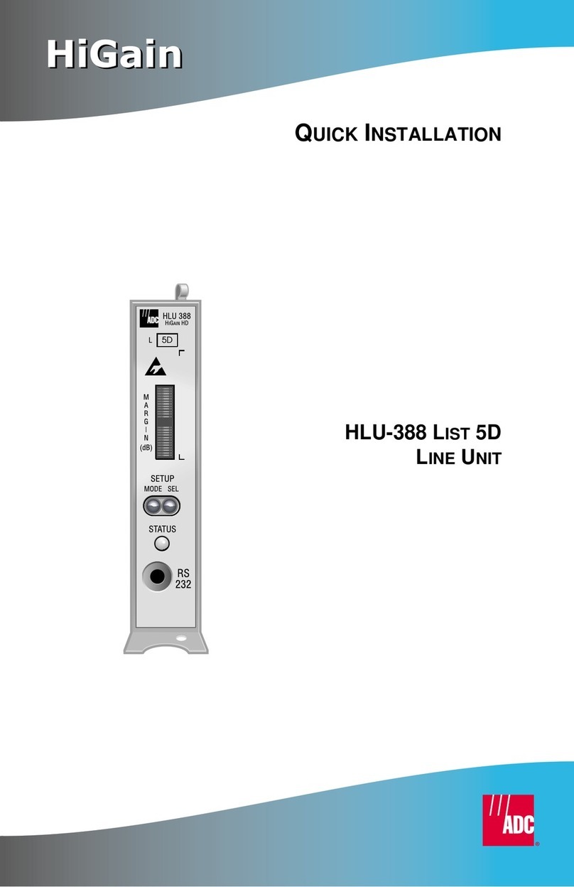
ADC HI GAIN H2TU-C-388 LIST 4G Original operating instructions

DNV C ertificatio n, Inc.
REGISTERED FIRM
ISO 9001/TL 9000
THE H2TU-C-388 LIST 4G
The H2TU-C-388 List 4G line unit is the Central Office (CO) side of a T1
transmissionsystem.TheH2TU-C,whenusedwithanH2TU-Rremoteunit,transmits
a 1.544 Mbps payload on one unconditioned copper pair over the full Carrier Service
Area (CSA) range. The H2TU-C-388 List 4G is designed to mount in Double Dual
Module Plus (DDM+) high-density mechanics shelves.
FEATURES
SPECIFICATIONS
Front-panel features: craft port for maintenance
screen access, six LEDs for system status
reporting, and DSX-1 access jacks
HDSL2 transmission features:
•Full-duplex transmission on one copper pair
•Grounded loop detection on HDSL2 span
•Souces sealing current
•Fractional T1 mode selection
Maintenance screens for inventory, provisioning,
performance monitoring, and troubleshooting,
including:
•Remote provisioning and PM data retrieval
through TL1 FDL commands
•Loop attenuation and insertion loss reporting
•Power Back Off (PBON and PBOC) for
configuring HDSL2 transmit power levels to
reduce crosstalk
•Report menu option for downloading status and
performance data
•Non-volatile storage of performance monitoring
parameters
•Customer disconnect indication alarms (AIS-CI
and RAI-CI alarm patterns)
•Performance Report Messaging (SPRM,
NPRM, and S + N)
Operating Temperature -40°F to +149°F (-40°C to +65°C)
Operating Humidity 5% to 95% non-condensing
HDSL2 Span Voltage 0 or -180 Vdc ±5 Vdc
CO Supply -48 Vdc nominal (-42.5 Vdc to -56.5 Vdc)
Mounting DDM+ high-density shelf
HDSL2 Line Rate 1.552 Mbps Overlapped Pulse Amplitude Modulation Transmission
with Interlocking Spectra (OPTIS)
HDSL2 Output +16.8 dBm ±0.5 dBm, 135Ωat CO side
+16.5 dBm ±0.5 dBm, 135Ωat remote side
Maximum Insertion Loss 35 dB @ 196 kHz
Maximum Loop Attenuation 28 dB
DSX-1 Line Rate 1.544 Mbps ±200 bps
DSX-1 Line Format Alternate Mark Inversion (AMI) or Bipolar with 8-Zero Substitution (B8ZS)
DSX-1 Frame Format Extended SuperFrame (ESF), SuperFrame (SF), or Unframed (UNFR)
DSX-1 Pulse Output 6 Vpk-pk, pre-equalized for 0 to 655 feet of ABAM cable
DSX-1 Input Level +1.5 dB to -7.5 dB DSX
INSTALLATION
Raise the H2TU-C front panel. Align the H2TU-C with the shelf card-slot guides and
slide the unit in. Press down on the front panel to secure the unit in the shelf.
POWER-UPSEQUENCE
When the H2TU-C powers up, the DSL LED flashes red once every second.
If the H2TU-C is unable to communicate with the H2TU-R, the DSL LED displays
solid red, indicating HBER, MARG, or PWRF alarms.
If the H2TU-C is able to communicate with the H2TU-R, theDSL LED displays solid
green, indicating that the HDSL2 spans are synchronized without error.
Verify the presence of a DS1 signal by confirming that the ALM LED is off (not lit).
If the ALM LED displays red oryellow, a DS1LOS condition exisits. Refer to Table 2
to locate the problem.
Verify error-free DS1 transmission by confirming that the DS1, framing (ESF/SF),
and line code (B8ZS/AMI) LEDs display solid colors. Refer to Table 2 to locate the
problem if these LEDs are either flashing or display solid red.
PROVISIONING
Perform these basic provisioning tasks:
1Connect a maintenance terminal to the craft port (see front-panel illustration
inside) and log on. Press + to refresh the logon screen, if necessary.
Refer to the onscreen Help menu for navigational aids or use the (to
cycle through selections), (to activate the current setting, choice, or to
display a menu), or (to return to the parent menu), or directional
arrow keys (to navigate to a menu or item)
2Select Config, Date and Time, then type the date and time.
3Select Inventory, then type the unit ID numbers.
4Change the settings of any system parameters, if necessary, by selecting Config,
then Standard Options or ADC Options. (See Table 3 and Table 4 inside.)
Once the H2TU-C is successfully installed and provisioned, access the Monitor,
Performance, or Event Log menus to clear the Performance, Alarm History, or Event
Log screens, or use Master Clear in the Config menu.
Continued
CTRL R
SPACEBAR
ENTER
ESC F11
Þ
HIGAIN H2TU-C-388 LIST 4G
LINE UNIT
QUICK INSTALLATION
FCC Class A Compliance
This equipment has been tested and found to comply with the limits for a Class A digital device, pursuant to
Part 15 of the FCC Rules. These limits are designed to provide reasonable protection against harmful
interference when the equipment is operated in a commercial environment. This equipmentgenerates, uses,
and can radiate radio frequency energy and, if not installed and used in accordance with the instruction
manual, may cause harmful interference to radio communications. Operation of this equipment in a
residential area is likely to cause harmful interference in which case the user will be required to correct the
interference at his own expense.
Limited Warranty
Product warranty is determined by your service agreement. Contact your sales representative or Customer
Service for details.
Modifications
Any changes or modifications made to this device that are not expressly approved by ADC DSL Systems,
Inc. voids the user's warranty.
All wiring external to the products should follow the provisions of the current edition of the National
Electrical Code.
Standards Compliance
This equipment has been tested and verified to comply with the applicable sections of the following safety
standards:
❑GR 63-CORE - Network Equipment-Building System (NEBS) Requirements
❑GR 1089-CORE - Electromagnetic Compatibility and Electrical Safety
❑Binational standard, UL-1950/CSA C22.2 No. 950-95: Safety of Information Technology Equipment.
Trademark Information
ADC is a registered trademark of ADC Telecommunications, Inc. Other product names mentioned in this
installation guide are used for identification purposes only and may be trademarks or registered trademarks
of their respective companies.
Copyright Information
© 2002 ADC DSL Systems, Inc. All rights reserved. Information contained in this document is company
private to ADC DSL Systems, Inc., and shall not be modified, used, copied, reproduced or disclosed in
whole or in part without the written consent of ADC.
ADC DSL Systems, Inc.
14402 Franklin Avenue
Tustin, CA 92780-7013
Tel: 714.832.9922
Fax: 714.832.9924
Technical Assistance
Tel: 800.638.0031
Tel: 714.730.3222
Fax: 714.730.2400 1236247
´,D8¶7W¨
July 3, 2002
Product Catalog: H2TU-C-388-L4G
CLEI: VACJDK4E
Document: LTPH-QI-1152-01

DNV C ertificatio n, Inc.
REGISTERED FIRM
ISO 9001/TL 9000
THE H2TU-C-388 LIST 4G
The H2TU-C-388 List 4G line unit is the Central Office (CO) side of a T1
transmissionsystem.The H2TU-C, when used withan H2TU-R remoteunit,transmits
a 1.544 Mbps payload on one unconditioned copper pair over the full Carrier Service
Area (CSA) range. The H2TU-C-388 List 4G is designed to mount in Double Dual
Module Plus (DDM+) high-density mechanics shelves.
FEATURES
SPECIFICATIONS
Front-panel features: craft port for maintenance
screen access, six LEDs for system status
reporting, and DSX-1 access jacks
HDSL2 transmission features:
•Full-duplex transmission on one copper pair
•Grounded loop detection on HDSL2 span
•Souces sealing current
•Fractional T1 mode selection
Maintenance screens for inventory, provisioning,
performance monitoring, and troubleshooting,
including:
•Remote provisioning and PM data retrieval
through TL1 FDL commands
•Loop attenuation and insertion loss reporting
•Power Back Off (PBON and PBOC) for
configuring HDSL2 transmit power levels to
reduce crosstalk
•Report menu option for downloading status and
performance data
•Non-volatile storage of performance monitoring
parameters
•Customer disconnect indication alarms (AIS-CI
and RAI-CI alarm patterns)
•Performance Report Messaging (SPRM,
NPRM, and S + N)
Operating Temperature -40°F to +149°F (-40°C to +65°C)
Operating Humidity 5% to 95% non-condensing
HDSL2 Span Voltage 0 or -180 Vdc ±5 Vdc
CO Supply -48 Vdc nominal (-42.5 Vdc to -56.5 Vdc)
Mounting DDM+ high-density shelf
HDSL2 Line Rate 1.552 Mbps Overlapped Pulse Amplitude Modulation Transmission
with Interlocking Spectra (OPTIS)
HDSL2 Output +16.8 dBm ±0.5 dBm, 135Ωat CO side
+16.5 dBm ±0.5 dBm, 135Ωat remote side
Maximum Insertion Loss 35 dB @ 196 kHz
Maximum Loop Attenuation 28 dB
DSX-1 Line Rate 1.544 Mbps ±200 bps
DSX-1 Line Format Alternate Mark Inversion (AMI) or Bipolar with 8-Zero Substitution (B8ZS)
DSX-1 Frame Format Extended SuperFrame (ESF), SuperFrame (SF), or Unframed (UNFR)
DSX-1 Pulse Output 6 Vpk-pk, pre-equalized for 0 to 655 feet of ABAM cable
DSX-1 Input Level +1.5 dB to -7.5 dB DSX
INSTALLATION
Raise the H2TU-C front panel. Align the H2TU-C with the shelf card-slot guides and
slide the unit in. Press down on the front panel to secure the unit in the shelf.
POWER-UPSEQUENCE
When the H2TU-C powers up, the DSL LED flashes red once every second.
If the H2TU-C is unable to communicate with the H2TU-R, the DSL LED displays
solid red, indicating HBER, MARG, or PWRF alarms.
If the H2TU-C is able to communicate with the H2TU-R, theDSL LED displays solid
green, indicating that the HDSL2 spans are synchronized without error.
Verify the presence of a DS1 signal by confirming that the ALM LED is off (not lit).
If the ALM LED displays red oryellow, a DS1LOS condition exisits. Refer to Table 2
to locate the problem.
Verify error-free DS1 transmission by confirming that the DS1, framing (ESF/SF),
and line code (B8ZS/AMI) LEDs display solid colors. Refer to Table 2 to locate the
problem if these LEDs are either flashing or display solid red.
PROVISIONING
Perform these basic provisioning tasks:
1Connect a maintenance terminal to the craft port (see front-panel illustration
inside) and log on. Press + to refresh the logon screen, if necessary.
Refer to the onscreen Help menu for navigational aids or use the (to
cycle through selections), (to activate the current setting, choice, or to
display a menu), or (to return to the parent menu), or directional
arrow keys (to navigate to a menu or item)
2Select Config, Date and Time, then type the date and time.
3Select Inventory, then type the unit ID numbers.
4Change the settings of any system parameters, if necessary, by selecting Config,
then Standard Options or ADC Options. (See Table 3 and Table 4 inside.)
Once the H2TU-C is successfully installed and provisioned, access the Monitor,
Performance, or Event Log menus to clear the Performance, Alarm History, or Event
Log screens, or use Master Clear in the Config menu.
Continued
CTRL R
SPACEBAR
ENTER
ESC F11
Þ
HIGAIN H2TU-C-388 LIST 4G
LINE UNIT
QUICK INSTALLATION
FCC Class A Compliance
This equipment has been tested and found to comply with the limits for a Class A digital device, pursuant to
Part 15 of the FCC Rules. These limits are designed to provide reasonable protection against harmful
interference when the equipment is operated in a commercial environment. This equipmentgenerates, uses,
and can radiate radio frequency energy and, if not installed and used in accordance with the instruction
manual, may cause harmful interference to radio communications. Operation of this equipment in a
residential area is likely to cause harmful interference in which case the user will be required to correct the
interference at his own expense.
Limited Warranty
Product warranty is determined by your service agreement. Contact your sales representative or Customer
Service for details.
Modifications
Any changes or modifications made to this device that are not expressly approved by ADC DSL Systems,
Inc. voids the user's warranty.
All wiring external to the products should follow the provisions of the current edition of the National
Electrical Code.
Standards Compliance
This equipment has been tested and verified to comply with the applicable sections of the following safety
standards:
❑GR 63-CORE - Network Equipment-Building System (NEBS) Requirements
❑GR 1089-CORE - Electromagnetic Compatibility and Electrical Safety
❑Binational standard, UL-1950/CSA C22.2 No. 950-95: Safety of Information Technology Equipment.
Trademark Information
ADC is a registered trademark of ADC Telecommunications, Inc. Other product names mentioned in this
installation guide are used for identification purposes only and may be trademarks or registered trademarks
of their respective companies.
Copyright Information
© 2002 ADC DSL Systems, Inc. All rights reserved. Information contained in this document is company
private to ADC DSL Systems, Inc., and shall not be modified, used, copied, reproduced or disclosed in
whole or in part without the written consent of ADC.
ADC DSL Systems, Inc.
14402 Franklin Avenue
Tustin, CA 92780-7013
Tel: 714.832.9922
Fax: 714.832.9924
Technical Assistance
Tel: 800.638.0031
Tel: 714.730.3222
Fax: 714.730.2400 1236247
´,D8¶7W¨
July 3, 2002
Product Catalog: H2TU-C-388-L4G
CLEI: VACJDK4E
Document: LTPH-QI-1152-01

LOOPBACK TESTING
Initiate loopback testing from the maintenance menus. The inband codes shown below can
be sent by a test set.
Table 1. GNLB Loopback Commands
Loopback Inband Code Description
NLOC 1111000 DSX-1 signal is looped back to the network at the H2TU-C.
NREM 1110000 DSX-1 signal is looped back to the network at the H2TU-R.
CREM 1111110 DS1 signal from customer is looped back to the customer at the H2TU-C.
CLOC 1111100 DS1 signal from customer is looped back to the customer at the H2TU-R.
SMJK 11000 DSX-1 signal is looped back to the network at the H2TU-R SmartJack module.
Loopdown 11100 Deactivates any of the above loopbacks.
Table 2. LED Status and Functions
LED and Status Function
DSL
OFF No power is applied to the H2TU-C.
Solid green Normal operation: HDSL2 span is synchronized without error.
Solid red HBER, MARG, or PWRF alarm is present at the H2TU-C.
Flashing red once every second HDSL2 loop is attempting synchronization.
ALM
OFF Normal operation: the DSX-1 signal is present at both the H2TU-R and
H2TU-C.
Solid yellow RLOS is present at the H2TU-R.
Solid red LLOS is present at the H2TU-C.
DSX/DS1
Solid green Normal operation: the DSX-1 signal is error free.
Solid red LLOS, BPV, frame error, or CRC is present at the H2TU-C.
ESF/SF
OFF Unframed DSX-1 is present at the H2TU-C, unit set as unframed, or no
DSX-1 is detected at the H2TU-C.
Solid yellow ESF frame formatting is present at the H2TU-C.
Flashing yellow once every second ESF frame formatting and frame error/CRC are present at the H2TU-C.
Solid green SF frame formatting is present at the H2TU-C.
Flashing green once every second SF frame formatting and frame error are present at the H2TU-C.
B8ZS/AMI
OFF No DSX-1 signal is present at the H2TU-C.
Solid yellow B8ZS is present at the H2TU-C.
Flashing yellow once every second B8ZS and excess zeros string are present at the H2TU-C.
Solid green AMI is present at the H2TU-C.
Flashing green once every second AMI and BPV are present at the H2TU-C.
LBK
OFF H2TU-C is not in loopback.
Solid yellow H2TU-C is in either NLOC or CREM (RLB).
To comply with the intrabuilding wiring requirements of GR-1089
CORE, Section 4.5.9, the shields of the ABAM-type cables that
connect the line unit DSX-1 output ports to the cross-connect
panel must be grounded at both ends.
Network
H2TU-C H2TU-R
TLOS*
NLOC CREM CLOC
NREM
SMJK
* When enabled,TLOS is an automatic loopback
that occurs with an LOS at the remote DS1 input.
Downstream
Upstream
Customer
Premises
DS1
DSX-1
H0025-A
Table 3. Maintenance Terminal Config Menu—Standard Options(a)
(a) Default settings are in bold.
Standard Option Function
Loopback Timeout
(LBTO) Sets automatic cancellation of all loopbacks to NONE, 20 min, 60 min, or
120 min after activation.
Loop Attenuation
Threshold (LATT) Determines the maximum loop attenuation (0 to 40 dB) before an alarm is
declared. Zero disables the alarm. Default setting is 32 dB.
Margin Threshold
(MARG) Determines the minimum allowable margin (0 to 15 dB) below which a system
alarm can occur. Zero disables the alarm. Default setting is 4 dB.
DS1 Frame Formatting
(FRMG) AUTO = system searches DS1 transmission for SF or ESF frame pattern.
SF = sets system for SF frame formatting.
ESF = sets system for ESF frame formatting.
UNFR = system functions as a transparent bit pipe.
DS1 Line Coding (DS1) B8ZS = sets system for B8ZS line code.
AMI = sets system for AMI line code.
H2TU-C Equalization
(EQL) Sets the DSX-1 equalizer to: 0 (0 to 132 ft.), 133 (133 to 265 ft.), 266 (266 to
398 ft.), 399 (399 to 532 ft.), or 533 (533 to 655 ft.).
H2TU-R Line Buildout
(RLBO) Sets the DS1 receive level output toward the Customer Interface to 0 dB,
-7.5 dB, or -15.0 dB.
Alarm Pattern (ALMP) Enables an AIS or LOS output at the DS1 ports for LOSW or LOS DS1.
H2TU-R TLOS Loopback
(TLOS) Enables (ENA) or disables (DIS) a TLOS loopback at H2TU-R for LOS at its
DS1 input (if enabled at the H2TU-R).
Network Loopback
Pattern (NLBP) Enables the H2TU-R to transmit an AIS or LOS towards CI for any network
loopback.
Power Back Off Network
(PBON) The power output levels of the H2TU-C network unit toward the customer.
Default (DEF) or enhanced (ENH).
Power Back Off Customer
(PBOC) The power output levels of the H2TU-R customer unit toward the network.
Default (DEF) or enhanced (ENH).
Table 4. Maintenance Terminal Config Menu—ADC Options(a)
(a) Default settings are in bold.
ADC Option Function
Line Power Feed (PWRF) Enables (ON) or disables (OFF) HDSL2 line power.
Remote Provisioning
(RTPV) Enables (ENA)or disables (DIS) remote provisioning.
Bipolar Violation
Transparency (BPVT) Enables (ENA) or disables (DIS) Bipolar Violation Transparency.
DS1 BER (DBER) Enables (ENA) or disables (DIS) 24-hour DSX-1 BER alarm threshold.
HDSL2 BER Threshold
(HBER) Sets HDSL2 BER alarm threshold at 1E-6, 1E-7 or NONE.
Special Loopback Mode
(SPLB) Configures system for generic (GNLB) or special inband loopback command
(A3LB).
SmartJack Loopback
(LPBK) Enables (ENA)or disables (DIS) SmartJack (SMJK) loopback commands.
Network AIS Pattern
(NAIS) If ALMP is set to AIS, determines which pattern is sent to the network when a
remote LOS or AIS occurs. CI = AIS-CI sent to the network; AIS = AIS sent to
the network.
Performance Report
Messaging (PRM) OFF = no enhanced Performance Report Messaging, SPRM = Supplemental
PRM, NPRM = Network PRM, S + N = H2TU-R generates both SPRMs and
NPRMs whenever possible.
RAI to RAI-CI towards
NET (RACI) Enables (ENA) or disables (DIS) conversion of a DS1 RAI signal (yellow alarm)
received by the H2TU-R to an RAI-CI signal toward the network.
ESF-RAI to SF-RAI
Overwrite (ROVR) Enables (ENA) or disables (DIS) conversion of an ESF DS1 payload from the
network with an embedded RAI pattern to an SF-RAI pattern toward the CI at
the H2TU-R. CONV option must be set to FCON or ACON.
H2TU-R DS1 Frame
Conversion (CONV) OFF = framing determined by the DS1 FRMG option, ACON = autodetection of
framing and potential frame conversion at the H2TU-R, FCON = autodetection
of framing and forced frame format conversion at the H2TU-R.
Fractional T1 Mode (FT1) Enables (ENA) or disables (DIS) system response to DDS latching loopback
commands for fractional T1 applications, CP disconnect, and trouble
indication.
Copies of this publication or the user manual (LTPH-UM-1169-xx)
can be downloaded from the ADC website at www.adc.com. To
order a hard copy, please contact your sales representative.
Front Panel
Card-Edge Connector
106
105
104
103
102
101
100
DSX-1OUT
DSX-1IN
205
204
203
202
201
200
119
118
117
116
115
114
113
112
111
110
GND GND
FrameGND
Fusealarm*
Ring1
Tip1
Management bus
Ring
Tip
Factoryburn-in
-48Vdc
219
218
217
216
215
214
213
212
211
210
209
208
207
206
109
108
107
* Fuse alarm is normally floating (0 to 80 Vdc max.) and
at -48 Vdc (10 mA max.) when activated.
HDSL2Span
Ring
Tip
Craft port
List number
CLEI/ECI bar code label
(inside handle)
Handle
MaintenanceTerminal Modem Settings
9600 baud
8 data bits
No parity
1 stop bit
Hardware flow control:OFF
Terminal emulation:VT100
DSX-1 access jacks
Connect standard test equipment.
LINE Provides splitting jack access to
(IN) and from (OUT) the HDSL2 span
at the DSX-1 interface.
MON Provides non-intrusive monitoring jack
access to (IN) and from (OUT) the
HDSL2 span at the DSX-1 interface.
Allows monitoring of the T1 payloads.
To access all system maintenance, provisioning
and performance screens, connect a standard
DB-9 terminal cable between the serial port
on a PC and the H2TU-C craft port.
Status LEDs
H0061-A
H2TU-C 388
DSL
LINE
I
N
I
N
O
U
T
O
U
T
ALM
DSX
DS1
ESF
SF
YEL
GRN
B8ZS
AMI
LBK
MON DSX1
RS 232 DCE
L

DNV C ertificatio n, Inc.
REGISTERED FIRM
ISO 9001/TL 9000
THE H2TU-C-388 LIST 4G
The H2TU-C-388 List 4G line unit is the Central Office (CO) side of a T1
transmissionsystem.The H2TU-C, when used withan H2TU-R remoteunit,transmits
a 1.544 Mbps payload on one unconditioned copper pair over the full Carrier Service
Area (CSA) range. The H2TU-C-388 List 4G is designed to mount in Double Dual
Module Plus (DDM+) high-density mechanics shelves.
FEATURES
SPECIFICATIONS
Front-panel features: craft port for maintenance
screen access, six LEDs for system status
reporting, and DSX-1 access jacks
HDSL2 transmission features:
•Full-duplex transmission on one copper pair
•Grounded loop detection on HDSL2 span
•Souces sealing current
•Fractional T1 mode selection
Maintenance screens for inventory, provisioning,
performance monitoring, and troubleshooting,
including:
•Remote provisioning and PM data retrieval
through TL1 FDL commands
•Loop attenuation and insertion loss reporting
•Power Back Off (PBON and PBOC) for
configuring HDSL2 transmit power levels to
reduce crosstalk
•Report menu option for downloading status and
performance data
•Non-volatile storage of performance monitoring
parameters
•Customer disconnect indication alarms (AIS-CI
and RAI-CI alarm patterns)
•Performance Report Messaging (SPRM,
NPRM, and S + N)
Operating Temperature -40°F to +149°F (-40°C to +65°C)
Operating Humidity 5% to 95% non-condensing
HDSL2 Span Voltage 0 or -180 Vdc ±5 Vdc
CO Supply -48 Vdc nominal (-42.5 Vdc to -56.5 Vdc)
Mounting DDM+ high-density shelf
HDSL2 Line Rate 1.552 Mbps Overlapped Pulse Amplitude Modulation Transmission
with Interlocking Spectra (OPTIS)
HDSL2 Output +16.8 dBm ±0.5 dBm, 135Ωat CO side
+16.5 dBm ±0.5 dBm, 135Ωat remote side
Maximum Insertion Loss 35 dB @ 196 kHz
Maximum Loop Attenuation 28 dB
DSX-1 Line Rate 1.544 Mbps ±200 bps
DSX-1 Line Format Alternate Mark Inversion (AMI) or Bipolar with 8-Zero Substitution (B8ZS)
DSX-1 Frame Format Extended SuperFrame (ESF), SuperFrame (SF), or Unframed (UNFR)
DSX-1 Pulse Output 6 Vpk-pk, pre-equalized for 0 to 655 feet of ABAM cable
DSX-1 Input Level +1.5 dB to -7.5 dB DSX
INSTALLATION
Raise the H2TU-C front panel. Align the H2TU-C with the shelf card-slot guides and
slide the unit in. Press down on the front panel to secure the unit in the shelf.
POWER-UPSEQUENCE
When the H2TU-C powers up, the DSL LED flashes red once every second.
If the H2TU-C is unable to communicate with the H2TU-R, the DSL LED displays
solid red, indicating HBER, MARG, or PWRF alarms.
If the H2TU-C is able to communicate with the H2TU-R, theDSL LED displays solid
green, indicating that the HDSL2 spans are synchronized without error.
Verify the presence of a DS1 signal by confirming that the ALM LED is off (not lit).
If the ALM LED displays red oryellow, a DS1LOS condition exisits. Refer to Table 2
to locate the problem.
Verify error-free DS1 transmission by confirming that the DS1, framing (ESF/SF),
and line code (B8ZS/AMI) LEDs display solid colors. Refer to Table 2 to locate the
problem if these LEDs are either flashing or display solid red.
PROVISIONING
Perform these basic provisioning tasks:
1Connect a maintenance terminal to the craft port (see front-panel illustration
inside) and log on. Press + to refresh the logon screen, if necessary.
Refer to the onscreen Help menu for navigational aids or use the (to
cycle through selections), (to activate the current setting, choice, or to
display a menu), or (to return to the parent menu), or directional
arrow keys (to navigate to a menu or item)
2Select Config, Date and Time, then type the date and time.
3Select Inventory, then type the unit ID numbers.
4Change the settings of any system parameters, if necessary, by selecting Config,
then Standard Options or ADC Options. (See Table 3 and Table 4 inside.)
Once the H2TU-C is successfully installed and provisioned, access the Monitor,
Performance, or Event Log menus to clear the Performance, Alarm History, or Event
Log screens, or use Master Clear in the Config menu.
Continued
CTRL R
SPACEBAR
ENTER
ESC F11
Þ
HIGAIN H2TU-C-388 LIST 4G
LINE UNIT
QUICK INSTALLATION
FCC Class A Compliance
This equipment has been tested and found to comply with the limits for a Class A digital device, pursuant to
Part 15 of the FCC Rules. These limits are designed to provide reasonable protection against harmful
interference when the equipment is operated in a commercial environment. This equipmentgenerates, uses,
and can radiate radio frequency energy and, if not installed and used in accordance with the instruction
manual, may cause harmful interference to radio communications. Operation of this equipment in a
residential area is likely to cause harmful interference in which case the user will be required to correct the
interference at his own expense.
Limited Warranty
Product warranty is determined by your service agreement. Contact your sales representative or Customer
Service for details.
Modifications
Any changes or modifications made to this device that are not expressly approved by ADC DSL Systems,
Inc. voids the user's warranty.
All wiring external to the products should follow the provisions of the current edition of the National
Electrical Code.
Standards Compliance
This equipment has been tested and verified to comply with the applicable sections of the following safety
standards:
❑GR 63-CORE - Network Equipment-Building System (NEBS) Requirements
❑GR 1089-CORE - Electromagnetic Compatibility and Electrical Safety
❑Binational standard, UL-1950/CSA C22.2 No. 950-95: Safety of Information Technology Equipment.
Trademark Information
ADC is a registered trademark of ADC Telecommunications, Inc. Other product names mentioned in this
installation guide are used for identification purposes only and may be trademarks or registered trademarks
of their respective companies.
Copyright Information
© 2002 ADC DSL Systems, Inc. All rights reserved. Information contained in this document is company
private to ADC DSL Systems, Inc., and shall not be modified, used, copied, reproduced or disclosed in
whole or in part without the written consent of ADC.
ADC DSL Systems, Inc.
14402 Franklin Avenue
Tustin, CA 92780-7013
Tel: 714.832.9922
Fax: 714.832.9924
Technical Assistance
Tel: 800.638.0031
Tel: 714.730.3222
Fax: 714.730.2400 1236247
´,D8¶7W¨
July 3, 2002
Product Catalog: H2TU-C-388-L4G
CLEI: VACJDK4E
Document: LTPH-QI-1152-01
Table of contents
Other ADC Microphone System manuals